US402793A - Machine - Google Patents
Machine Download PDFInfo
- Publication number
- US402793A US402793A US402793DA US402793A US 402793 A US402793 A US 402793A US 402793D A US402793D A US 402793DA US 402793 A US402793 A US 402793A
- Authority
- US
- United States
- Prior art keywords
- lever
- cam
- roller
- fabric
- link
- Prior art date
- Legal status (The legal status is an assumption and is not a legal conclusion. Google has not performed a legal analysis and makes no representation as to the accuracy of the status listed.)
- Expired - Lifetime
Links
- 239000004744 fabric Substances 0.000 description 20
- 210000000614 Ribs Anatomy 0.000 description 8
- 238000009940 knitting Methods 0.000 description 8
- 238000010276 construction Methods 0.000 description 6
- 230000000875 corresponding Effects 0.000 description 4
- 230000003292 diminished Effects 0.000 description 4
- 210000000474 Heel Anatomy 0.000 description 2
- 206010022000 Influenza Diseases 0.000 description 2
- 241000382509 Vania Species 0.000 description 2
- 230000002159 abnormal effect Effects 0.000 description 2
- 239000000969 carrier Substances 0.000 description 2
- 230000000881 depressing Effects 0.000 description 2
- 230000000694 effects Effects 0.000 description 2
- 101700055763 spri Proteins 0.000 description 2
- 238000004804 winding Methods 0.000 description 2
Images


Classifications
-
- D—TEXTILES; PAPER
- D04—BRAIDING; LACE-MAKING; KNITTING; TRIMMINGS; NON-WOVEN FABRICS
- D04B—KNITTING
- D04B9/00—Circular knitting machines with independently-movable needles
- D04B9/06—Circular knitting machines with independently-movable needles with needle cylinder and dial for ribbed goods
Definitions
- PETERS Ffwlwlilbogrnphor, Waihinglnn. n. c.
- WITNESSES INVENTOR Q/Y. I uwm I w W PETERS. shnwunw n mr. Wuhinglan', 0. a
- My invention is particularly adapted for use in connection with machines of the type described in' Letters Patent of the United States No. 284,591, granted to myself and others under date of September 11, 1883; but
- Figure 1 represents a front elevation of a machine embodying my improvements; Fig. 2, the top or plan view thereof.
- Figs. 3 and at are vertical sections representing, on an enlarged scale, certain details of belt-shifting mechanism.
- Fig. 5 is a vertical section through the center of the needle-cylinder, but on an enlarged 2 5 scale.
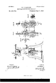
- Figs. 6 and 7 are views of the patternchain-carrier roll, Fig. 7 being a transverse section thereof on a line, 2' z, of Fig. (3.
- Fig. 8 is a side elevation of the machine, or aview at right angles to Fig. 1, the needle-cylinder 0 and appurtenances being omitted.
- Figs. 9 is a side elevation of the machine, or aview at right angles to Fig. 1, the needle-cylinder 0 and appurtenances being omitted.
- Fig. 16 is a vertical section through said segment on the line y y of Fig. 15, the scale of the four last-mentioned figures being very much enlarged and the said segment being represented, for convenience of illustration, as standing upon one end.
- the present invention relates particularly to the following-mentioned groups of mechanism, and has the following objects: First, the cam-ring provided with removable segments and of peculiar construction to permit ready access to the needles; second, the stopmotion, which is not only arranged to act automatically on the occurrence of a defect in the fabric, but is also provided with a very simple and easily-worked hand attachment for stopping the machine; third, the tension mechanism and fabric-roller, which are automatically actuated and rendered capable of a very delicate adjustment to suit the varying requirements of the fabric.
- the cam-ring provided with removable segments and of peculiar construction to permit ready access to the needles
- the stopmotion which is not only arranged to act automatically on the occurrence of a defect in the fabric, but is also provided with a very simple and easily-worked hand attachment for stopping the machine
- third the tension mechanism and fabric-roller, which are automatically actuated and rendered capable of a very delicate adjustment to suit the varying requirements of the fabric.
- A represents the horizontal bed plate or table of the machine, supported upon housings and legs A.'
- the machine also has the usual dial-plate, A, carrying the horizontal needles Q), having the usual cam-plate, A and shifting devices A A operated by means of a pat tern-chain, a. Since the construction of these 7 5 devices is well understood, and as they form no partof the present invention, further description is unnecessary.
- H H are the two vertical side pieces of the rotating pendent frame which carries the tension devices and the fabric-roller, said frame being attached in the usual manner to the retating needle-cylinder.
- the cam-ring B hastwo sets of operating-cams arranged diametrically to andcounterparts of one another. The description of one of these will therefore suffice.
- Each group of operating-cams is arranged in a removable segment, B, attached to the cam-ring B by means of screws passing 0 through openings 5 in said removable segment into the cam-ring.
- c c c are the cams, the two latter being fixed, while the cam c is made vertically adjustable in the fol- 5 lowing manner: A deep vertical slot, 6, is cut in the inner face of the segment, and abloek,
- a spring, 6, is arranged beneath said block, and a set-screw, 6 is mount- 10o ed in the guard-piece C.
- This guard-piece C has its inner face curved in correspondence with the needle-cylinder, and is secured to the top of the segment B, with its inner face adjacent to the sides of the needles to prevent them from falling out of place.
- the guard-piece is slotted, as shown at C in order to permit the necessary range of upward mo tion of the cam C.
- the spring 12 sustains the cam c, the latter can obviously be set at any desired height by means of the screw 6 and thus a greater or less throw will be given to the needles.
- I construct that portion which is between the removable segments 13' of a height just suilieient for the projecting heel of the needles to rest thereon in rotating, and to prevent the needles from falling outward
- I provide two segmental guardpieces, D, (similar to the guard-pieces but longer, of course,) which are mounted upon a series of standards, (1, arranged at proper intervals upon the top of the intermediate low segments, Z), of the eamring.
- These guard-pieces Dare secured by means of screws to the standards (7, and can readily be removed, as also can the cam-segments B, so that access to the needles is greatly facilitated when it becomes necessary to remove or adjust them.
- the stop-motion which embodies the next feature of my invention, is arranged as follows:
- The-belt V is controlled by a belt-shifter, N mounted upon a horizontal rock-shaft,
- a lever, N having its bearing in the hanger N at the bottom of the lateral bracket N, which carries the outer journal of the driving-shaft.
- a lever, N having a lateral projection, as shown in Fig. 1, and to this projection is attached a horizontal link, f having on its upper side a notch which engages with a lug, 91, mounted upon the under side of the baseplate A.
- a spring, N normally tends to pull the lever N toward the right hand of Fig. 1, and consequently to throw it and the beltshifter N toward the loose pulley V Movement in that direction is, however, prevented by engagement of the lug n with said notch in the link f this position of the parts being shown in Fig. 1.
- the inner end of the link f is suspended by a light spring, f from the under side of the base-plate A, being held thereby in en gagement with the lug 72.
- a hole is formed in the base-plate immediately over the inner end of the link f and a hollow post, f, is mounted over said hole.
- a weighted drop stem, f slides freely in the hollow of said post and protrudes down through the hole in the table over the end of the link f Said stem has a range of vertical motion of such extent that when in its lowest position it will strike against the link f and it (the stem) is weighted sufficiently to overcome the tension of the spring by which said link is supported, so that upon falling it will. depress the linkf sutliciently to clear the lug n.
- the stem f is,
- a handle by which thebelt-shifter may be operated so as to start the machine, in order to facilitate its stoppage; also, by means of said handle I provide the following device, shown in detail in Fig. at: Avertical stem, g, slides in a longitudinal eav ity in said handle, being prevented from turning on its axis by means of a 1)il'l,- fitting in a vertical slot, g". Said stem is provided at its upper end with a spri ngeap, g normally holding the stem g in its uppermost position.
- Thelower end of the stem is in contact with the upper side of the link f before described; but of course by depressing the cap and stem the said link will be disengaged, whereupon the belt-shifting operation will take place in the same manner, as has just been described in the case of the automatic stopping device.
- the pattern-chain a is carried upon a roller, a, actuated in the ordinary manner by means of a pawl-and-ratchet device, actuated by a lever, .T,which is struck by the cam J, mounted upon the rotatingframcll ll.
- Said ratchet J is mounted upon one end of the chainroller a, which I construct as shown in Figs. 6 and 7.
- the tension device and fabric-roller are con structed and actuated in the following manner:
- Said tension devices consist of two rollers, II, (see Fig. 1 and the dotted lines of Fig. 8,) preferably having a flu ted surface or being covered with rubber to insure their clinging to the fabric Cwhich passes between them.
- the rollers I I are journaled at each end in vertically-movable supports it, (the details of which are shown in Fig. 11,) one of the rollers having fixed journals, while the other is mounted in a horizontally-sliding journalbox, 8, adjustable by means of the screw S, so that the rollers can set together to press against the fabric between them with any desired degree of force.
- the supports 25 t are mounted by means of studs or pins 19, projecting through vertical slots 7' r in the side frames, [-1 H, and are capable of a vertical movement of some inches.
- the supports ti are provided at each end with counterbalance-springs O O m m, and the latter pair are provided with set-screws m m whereby their tension may be increased or diminished.
- the support 25 carries, by means of pins which project through the slot 4", a strip or piece, arranged upon the outside of the frame H, and the upper end of said strip bears against a lever, Q, to whose outer end a spring, q, is attached, which is connected with the lever L.
- the shaft of the roller I carries a ratchet-wheel, K, having stop-pawls 76 and an actuating-pawl, k, which latter is mounted upon a lever, L, pivoted to the side of the frame H.
- the outer end of this lever is provided with a camroller, Z, adapted to run upon a segmental campiece, L, (see Figs. 1 and 8,) extending across one side of the machine.
- the downwardlypeudent link Z connects the lever L with a second and nearly similar lever, Z pivoted to one end of the side frame, H, and having a pawl, U, which engages with a ratchet-wheel, u, mounted upon the end ofthe shaft of the fabric-roller G by means of the friction attachment shown in sectional View of Fig. 12.
- the said ratchet-wheel a has a central opening countersunk on each side to receive on the one side the conical end a of the fabricroller shaft and on the opposite side a coneshaped washer or nut, it, provided with a set-screw, its, to hold it in position.
- the rollers I I may be made of any desired weight, and, as the whole of said weight (except so much as may be compensated by the springs m m) is borne by the fabric, the necessary degree of tension can be readily obtained. If for any reason the tendency of the roller to climb exceeds the downward delivery of completed fabric from the machine, so that the rollers would tend to mount too high, the upper end of the strip 15 will raise the lever Q, and by means of the connection qwill lift the lever L and the cam-roller Z, so that the lever will not again descend after passing the rise of the cam L ,but will be held clear of said cam during one or more rotations, during which time the delivery of fabric from above will have permitted the tension-roller I to descend.
- the actuatingdever therefor, and the fabrieroller having a pawl-and-ratchet device for actuating it, of the intermediate link connecting said first-mentioned lever with the pawl of the fabrieroller, whereby said fabric-roller is revolved in conformity with the movements of the tension-rolls, substantially as set forth.
Description
5 SheetsSheet 1.
(No Model.)
H. P. BALLOU. CIRCULAR RIB KNITTING MACHINE. No. 402,793. Patented May '7, 1889.
a e e a 5 e e e v we .e
e L g 5 N w i *1 9 =1 3E fi W I Lg 0 r log 9 wmqesses; INVENTOP :H fl
N. PETERS PMIv-Lilhogmphar. wahin mn, ac
(No Model.) 5 S-heetsSh eet 2.
H. P. BALLOU. GIRGULARRIB KNITTING MACHINE. No. 402,793. Patent-ed May 7, 1889.
INVENTOR I JKFMW N. PETERS. Pholulilhng'nplwr. Washington D. c.
(No Model.) 5 Sheets-Sheet 3.
H P BALLOU CIRCULAR RIB KNITTING MACHINE. No. 402,793. Patented May '7, 1889;
INVENTOR J KM n. PETERS Ffwlwlilbogrnphor, Waihinglnn. n. c.
(No Model.) S 5 Sheets-Sheet 4.
H. P. BALLOU. CIRCULAR RIB KNITTING MAGHINE. No. 402.793. Patented May 7,1889.
WITNESSES: INVENTOR Q/Y. I uwm I w W PETERS. shnwunw n mr. Wuhinglan', 0. a
(No Model.) 5 Sheets-Sheet 5.
H. P. BA-LLOU.
- CIRCULAR RIB KNITTING MACHINE.
Patented May INVENTOR Wi ma mmhnmn UNITED STATES A PATENT OFF-ICE.
HIRAM PEABODY EALLoU, OF BRISTOL, PENNSYLVANIA, ASSIGNOR TO LEWIS JONES, OF SAME PL CE.
CIRCULAR RIB-KNITTING MACHINE.
SPECIFICATION forming part of Letters Patent No. 402,793, dated May '7, 1889.
Application filed March 5, 1888. Serial No. 266,121. (No model.)
To all'whom it may concern.-
Be it known that I, HIEAM PEABoDY BAL- LOU, of the State of Massachusetts, but now residing at Bristol, in the State of Pennsyl- Vania, have invented certain new and useful Improvements in Circular Rib-Knitting Machines, whereof the following is a specification, reference being had to the accompanying drawings.
1'0 My invention is particularly adapted for use in connection with machines of the type described in' Letters Patent of the United States No. 284,591, granted to myself and others under date of September 11, 1883; but
it may, however, be used in connection with other machines.
In the accompanying drawings, Figure 1 represents a front elevation of a machine embodying my improvements; Fig. 2, the top or plan view thereof. Figs. 3 and at are vertical sections representing, on an enlarged scale, certain details of belt-shifting mechanism. Fig. 5 is a vertical section through the center of the needle-cylinder, but on an enlarged 2 5 scale. Figs. 6 and 7 are views of the patternchain-carrier roll, Fig. 7 being a transverse section thereof on a line, 2' z, of Fig. (3. Fig. 8 is a side elevation of the machine, or aview at right angles to Fig. 1, the needle-cylinder 0 and appurtenances being omitted. Figs. 9
and 10 are views of opposite sides of the retating pendent frame which carries the tension devices and fabric-roller. Figs. 11 and 12 are detail views of portions of the mech- 5 anism carried by said frame. Figs. 13, 14A,
and 15 are respectively outside, inside, and
plan views of a segment of the cam-ring; and
Fig. 16 is a vertical section through said segment on the line y y of Fig. 15, the scale of the four last-mentioned figures being very much enlarged and the said segment being represented, for convenience of illustration, as standing upon one end.
The present invention relates particularly to the following-mentioned groups of mechanism, and has the following objects: First, the cam-ring provided with removable segments and of peculiar construction to permit ready access to the needles; second, the stopmotion, which is not only arranged to act automatically on the occurrence of a defect in the fabric, but is also provided with a very simple and easily-worked hand attachment for stopping the machine; third, the tension mechanism and fabric-roller, which are automatically actuated and rendered capable of a very delicate adjustment to suit the varying requirements of the fabric. The peculiar operation of each of these groups, with my improvements, will be hereinafter described.
Referring to the drawings, A represents the horizontal bed plate or table of the machine, supported upon housings and legs A.'
B represents the cam ring or cylinder, and R the needle-cylinder having needles 1*, and provided on its lower side with teeth R, driven by the pinion w upon the inner end of the driving-shaft V. Said driving-shaft is provided with fast and loose pulleys V and Virespectively, power being imparted from the belt V. The machine also has the usual dial-plate, A, carrying the horizontal needles Q), having the usual cam-plate, A and shifting devices A A operated by means of a pat tern-chain, a. Since the construction of these 7 5 devices is well understood, and as they form no partof the present invention, further description is unnecessary.
H H are the two vertical side pieces of the rotating pendent frame which carries the tension devices and the fabric-roller, said frame being attached in the usual manner to the retating needle-cylinder. In the present instance the cam-ring B hastwo sets of operating-cams arranged diametrically to andcounterparts of one another. The description of one of these will therefore suffice.
Each group of operating-cams is arranged in a removable segment, B, attached to the cam-ring B by means of screws passing 0 through openings 5 in said removable segment into the cam-ring. (See Figs. 13,14,15, and 16.) Referring to Fig. 14, c c c are the cams, the two latter being fixed, while the cam c is made vertically adjustable in the fol- 5 lowing manner: A deep vertical slot, 6, is cut in the inner face of the segment, and abloek,
E, to which the cam c is attached, slides freely within said slot. A spring, 6, is arranged beneath said block, and a set-screw, 6 is mount- 10o ed in the guard-piece C. This guard-piece C has its inner face curved in correspondence with the needle-cylinder, and is secured to the top of the segment B, with its inner face adjacent to the sides of the needles to prevent them from falling out of place. The guard-piece is slotted, as shown at C in order to permit the necessary range of upward mo tion of the cam C. As the spring 12 sustains the cam c, the latter can obviously be set at any desired height by means of the screw 6 and thus a greater or less throw will be given to the needles.
Instead of continuing the cam-ring at the same level entirely around the cylinder, I construct that portion which is between the removable segments 13' of a height just suilieient for the projecting heel of the needles to rest thereon in rotating, and to prevent the needles from falling outward I provide two segmental guardpieces, D, (similar to the guard-pieces but longer, of course,) which are mounted upon a series of standards, (1, arranged at proper intervals upon the top of the intermediate low segments, Z), of the eamring. These guard-pieces Dare secured by means of screws to the standards (7, and can readily be removed, as also can the cam-segments B, so that access to the needles is greatly facilitated when it becomes necessary to remove or adjust them.
The stop-motion, which embodies the next feature of my invention, is arranged as follows: The-belt V is controlled by a belt-shifter, N mounted upon a horizontal rock-shaft,
N having its bearing in the hanger N at the bottom of the lateral bracket N, which carries the outer journal of the driving-shaft. To the other end of said rock-shaft N" is attached a lever, N, having a lateral projection, as shown in Fig. 1, and to this projection is attached a horizontal link, f having on its upper side a notch which engages with a lug, 91, mounted upon the under side of the baseplate A. A spring, N, normally tends to pull the lever N toward the right hand of Fig. 1, and consequently to throw it and the beltshifter N toward the loose pulley V Movement in that direction is, however, prevented by engagement of the lug n with said notch in the link f this position of the parts being shown in Fig. 1.
The inner end of the link f is suspended by a light spring, f from the under side of the base-plate A, being held thereby in en gagement with the lug 72. A hole is formed in the base-plate immediately over the inner end of the link f and a hollow post, f, is mounted over said hole. A weighted drop stem, f, slides freely in the hollow of said post and protrudes down through the hole in the table over the end of the link f Said stem has a range of vertical motion of such extent that when in its lowest position it will strike against the link f and it (the stem) is weighted sufficiently to overcome the tension of the spring by which said link is supported, so that upon falling it will. depress the linkf sutliciently to clear the lug n.
The stem f is,
however, normally held in a raised position by means of a simple bell-crank lever, l1, turning in a horizontal plane and having one end in very close proximity to the row of loops upon the needles 1*, while the other end engages with a horizontal groove, f extending around the stem f, near its upper end. A light spring, F, normally holds the end of the lever in position in said groove, thus sustaining the stem 1''.
I11 the operation of the machine it a lump or other prominent defect occurs in the work it will as the needlecylinde1.' rotates strike the inner end of the lever F and turn .it sufficiently to clear the groove f of the stem. The latter thereupon drops, and (by reason of its weight, as above stated) throws the link f out of engagement with the lug n. The spring N thereupon immediately throws the lever N and the belt-shifter N toward the loose pulley V thus stopping the machine.
At the upper end of the lever N is a handle, g, by which thebelt-shifter may be operated so as to start the machine, in order to facilitate its stoppage; also, by means of said handle I provide the following device, shown in detail in Fig. at: Avertical stem, g, slides in a longitudinal eav ity in said handle, being prevented from turning on its axis by means of a 1)il'l,- fitting in a vertical slot, g". Said stem is provided at its upper end with a spri ngeap, g normally holding the stem g in its uppermost position. Thelower end of the stem is in contact with the upper side of the link f before described; but of course by depressing the cap and stem the said link will be disengaged, whereupon the belt-shifting operation will take place in the same manner, as has just been described in the case of the automatic stopping device. I prefer to combine with the hand belt-shifter the above-described device, because the operator can work it to throw off the belt much more quickly than an ordinary shifter, it being merely necessary to strike the cap of the handle instead of grasping it and throwing it to one side. The pattern-chain a is carried upon a roller, a, actuated in the ordinary manner by means of a pawl-and-ratchet device, actuated by a lever, .T,which is struck by the cam J, mounted upon the rotatingframcll ll. Said ratchet J is mounted upon one end of the chainroller a, which I construct as shown in Figs. 6 and 7.
Instead of using a sprocket-wheel of the ordinary construction I use a cylinder having a series of longitudinal ribs or flanges, (R, at intervals, which correspond with the length of the chain-links, and I cut notches a in said ribs circumferential to the cylinder, said notches being of such depth and width as to receive those links which are only single thickness. The quick jerking movement by which such chains are actuated renders it extremely difficult in practice to keep the links in place, as they continually jump oil? the studs of the sprocket-wheel, and in so doing break up the entire pattern. I have found that the above-described device absolutely prevents any such shifting or slipping of the links, and hence can be run at a high rate of speed with perfect safety.
The tension device and fabric-roller are con structed and actuated in the following manner: Said tension devices consist of two rollers, II, (see Fig. 1 and the dotted lines of Fig. 8,) preferably having a flu ted surface or being covered with rubber to insure their clinging to the fabric Cwhich passes between them. The rollers I I are journaled at each end in vertically-movable supports it, (the details of which are shown in Fig. 11,) one of the rollers having fixed journals, while the other is mounted in a horizontally-sliding journalbox, 8, adjustable by means of the screw S, so that the rollers can set together to press against the fabric between them with any desired degree of force. At one end of the shaft of the roller I is a smallgear-wheel, '6, engagin g with a corresponding gear-wheel, 1 on the corresponding end of the other roller-shaft, so that when the roller I is rotated it will cause the other roller to rotate in the opposite direction and at the same rate of speed. The supports 25 t are mounted by means of studs or pins 19, projecting through vertical slots 7' r in the side frames, [-1 H, and are capable of a vertical movement of some inches. The supports ti are provided at each end with counterbalance-springs O O m m, and the latter pair are provided with set-screws m m whereby their tension may be increased or diminished. The support 25 carries, by means of pins which project through the slot 4", a strip or piece, arranged upon the outside of the frame H, and the upper end of said strip bears against a lever, Q, to whose outer end a spring, q, is attached, which is connected with the lever L. At its other end the shaft of the roller I carries a ratchet-wheel, K, having stop-pawls 76 and an actuating-pawl, k, which latter is mounted upon a lever, L, pivoted to the side of the frame H. The outer end of this lever is provided with a camroller, Z, adapted to run upon a segmental campiece, L, (see Figs. 1 and 8,) extending across one side of the machine. The downwardlypeudent link Z connects the lever L with a second and nearly similar lever, Z pivoted to one end of the side frame, H, and having a pawl, U, which engages with a ratchet-wheel, u, mounted upon the end ofthe shaft of the fabric-roller G by means of the friction attachment shown in sectional View of Fig. 12. The said ratchet-wheel a has a central opening countersunk on each side to receive on the one side the conical end a of the fabricroller shaft and on the opposite side a coneshaped washer or nut, it, provided with a set-screw, its, to hold it in position. By the adjustment of this set-screw a the frictional holding of the ratchet-wheel it upon the shaft of the fabric-roller can be increased or diminished, so that said shaft may be permit-ted to slip slightly, for a purpose which will hereinafter he explained.
The operation is as follows: At each rotation of the hanging frame H H the cam-roller [will mount and descend a cam-piece, L, and the lever L will thus be raised, so that the pawl 7c will rotate the ratchet-wheel K, the distance of one tooth, after which the lever and pawl will drop back into their original position. This rotation of the ratchet-wheel K will turn the roller 1, so as to advance 1t upward upon the fabric \V, the opposing roller, 1, being turned by means of the gears i t" in the opposite direction, so that the pair will climb together. The rollers I I may be made of any desired weight, and, as the whole of said weight (except so much as may be compensated by the springs m m) is borne by the fabric, the necessary degree of tension can be readily obtained. If for any reason the tendency of the roller to climb exceeds the downward delivery of completed fabric from the machine, so that the rollers would tend to mount too high, the upper end of the strip 15 will raise the lever Q, and by means of the connection qwill lift the lever L and the cam-roller Z, so that the lever will not again descend after passing the rise of the cam L ,but will be held clear of said cam during one or more rotations, during which time the delivery of fabric from above will have permitted the tension-roller I to descend. Thereupon the lever Q will fall again, so that the cam-roller Z can resume its operation. The aet'uatlo n of the lever L not only operates the tensionrollers, but by means of the pendent link I, lever Z pawl U, and ratchet a effects the rotation of the fabric-rollers G in a sin1ilar manner, thus winding up the finished fabr c IV. As the diameter of the roll of the fabric increases, the amount taken up by a given are of rotation, of course, increases also, and hence the regular movement of the ratchetwheel a would tend to wind up the fabric too rapidly were it not for the compensation afforded by the frictional mounting of the ratchet-wheel. This permits the ratchet to slip on the roller-shaft when the strain becomes excessive, so that only the proper quantity is wound up at each movement.
Having thus described my inventlon, I claim 1. The combination of the cam-ring having the operating cams mounted in removable segments with the intermediate segments at the level of the needle-heels, and the guardpieces mounted above said intermediate segments, substantially as described.
2. The combination of the belt shifter having a spring which normally tends to throw it toward the loose pulley, the pivoted link and the detent devices for holding the belt-shifter upon the driving-pulley, the dropstem mounted above said pivoted link, and the pivoted lever engaging said drop-stem to retain it in its upper position maintained in close proximity to the trzwel of the loops upon ITO the needles, whereby any abnormal prominence of a loop will actuate said lever to release the drop-stem, and thereby disengage the pivoted link and permit the shifting of the belt, substantially as set forth.
The combination of the beltshifter nor-- mally held toward the loose pulley by its spring", a pivoted link and the detent devices by which said link is adapted to hold the beltshifter upon the drivingpulley, and the han-.
5. The combination, with the tension-rolls I I, mounted in vertieallyunovable supports t i, and having a pawl and ratchet, of an actuating-lever for said pawl, a cam adapted to operate said lever, and a pivoted link arranged above one of said supports and connected with the pawl-actuating lever, whcreby the rise of the support beyond a definite point will lift the lever clear of the cam, substantially as set forth.
6. The combination, with the tension-rolls,
the actuatingdever therefor, and the fabrieroller having a pawl-and-ratchet device for actuating it, of the intermediate link connecting said first-mentioned lever with the pawl of the fabrieroller, whereby said fabric-roller is revolved in conformity with the movements of the tension-rolls, substantially as set forth.
HIRAM PEABODY BALLOU. 'Witnesses:
JOHN C. lVILLtAMs, JAMES H. LELL.
Publications (1)
| Publication Number | Publication Date |
|---|---|
| US402793A true US402793A (en) | 1889-05-07 |
Family
ID=2471747
Family Applications (1)
| Application Number | Title | Priority Date | Filing Date |
|---|---|---|---|
| US402793D Expired - Lifetime US402793A (en) | Machine |
Country Status (1)
| Country | Link |
|---|---|
| US (1) | US402793A (en) |
-
0
- US US402793D patent/US402793A/en not_active Expired - Lifetime
Similar Documents
| Publication | Publication Date | Title |
|---|---|---|
| US402793A (en) | Machine | |
| US274208A (en) | Knitting machine | |
| US83584A (en) | Improvement in knitting-machines | |
| US1942322A (en) | Knitting machine | |
| US980826A (en) | Take-up for knitting-machines. | |
| US1176776A (en) | Machine for unraveling and winding yarn. | |
| US645924A (en) | Knitting-machine. | |
| US410505A (en) | Circular-knitting machine | |
| US971911A (en) | Stop-motion. | |
| US521191A (en) | And george e | |
| US715154A (en) | Knitting-machine. | |
| US640874A (en) | Roving-machine. | |
| US1099772A (en) | Stop-motion. | |
| US1172764A (en) | Stop-motion for knitting-machines. | |
| US3390552A (en) | Apparatus for feeding elastic yarn | |
| US457307A (en) | dayis | |
| US415651A (en) | Island | |
| US1203092A (en) | Take-up mechanism for knitting-machines. | |
| US1302906A (en) | Yarn-reclaiming machine. | |
| US1218365A (en) | Warping-machine. | |
| US1373040A (en) | Yarn-winding machine | |
| US806065A (en) | Winder. | |
| US431913A (en) | newton | |
| US749062A (en) | Ihvehtor | |
| US319989A (en) | Machines |