US402101A - Machine for making axles - Google Patents
Machine for making axles Download PDFInfo
- Publication number
- US402101A US402101A US402101DA US402101A US 402101 A US402101 A US 402101A US 402101D A US402101D A US 402101DA US 402101 A US402101 A US 402101A
- Authority
- US
- United States
- Prior art keywords
- axle
- press
- die
- cylinders
- axles
- Prior art date
- Legal status (The legal status is an assumption and is not a legal conclusion. Google has not performed a legal analysis and makes no representation as to the accuracy of the status listed.)
- Expired - Lifetime
Links
- 239000002184 metal Substances 0.000 description 4
- 238000000034 method Methods 0.000 description 4
- 230000006835 compression Effects 0.000 description 1
- 238000007906 compression Methods 0.000 description 1
- 238000007599 discharging Methods 0.000 description 1
- 238000005553 drilling Methods 0.000 description 1
- 238000007730 finishing process Methods 0.000 description 1
- 238000010438 heat treatment Methods 0.000 description 1
- 239000007788 liquid Substances 0.000 description 1
- 238000004519 manufacturing process Methods 0.000 description 1
- 210000002445 nipple Anatomy 0.000 description 1
- 238000005498 polishing Methods 0.000 description 1
- 238000007517 polishing process Methods 0.000 description 1
Images
Classifications
-
- B—PERFORMING OPERATIONS; TRANSPORTING
- B21—MECHANICAL METAL-WORKING WITHOUT ESSENTIALLY REMOVING MATERIAL; PUNCHING METAL
- B21D—WORKING OR PROCESSING OF SHEET METAL OR METAL TUBES, RODS OR PROFILES WITHOUT ESSENTIALLY REMOVING MATERIAL; PUNCHING METAL
- B21D1/00—Straightening, restoring form or removing local distortions of sheet metal or specific articles made therefrom; Stretching sheet metal combined with rolling
- B21D1/14—Straightening frame structures
Definitions
- This invention pertains to machinery employed in the manufacture of vehicle-axles, and relates particularly to machinery for forming the collars upon the axles and giving the axles the proper set.
- the external taper is given to the spindles by two distinct plans.
- the axle is made of parallel cylindrical tubing, and the taper of the spindle is secured byturning down the end portions of the tube. This leaves the spindle portions of the axle of unreduced diameter internally, and leaves the walls thinner at the ends of the spindle in a degree represented byV the increase in the depth of :metal removed from the ends ofthe spindle in the process of turning the tapers.
- the other plan of producing the taper-spindles involves a swaging process, which, of course, results in an internal taper, as well as an external one, to the spindles.
- the A,surface-finish is given to the swaged spindles by any suitable turning or polishing process.
- My improved machinery is designed for operating upon the axle after the spindles have been tapered, assuming the spindles to be yof the taper kind, and the taper of the spindles i may have been produced by either of the methods above indicated.
- My. improved machinery is designed to form the collars integrally upon the axles and to give the spinf dles, if tapering, the proper degree of set.
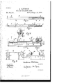
- Figure 1 is a side elevation (part vertical longitudinal section) of a tubular axle in that unfinished stage, in which it is ready for operation of my improved machinery, the axle in this stage being without collars and without set, and having a length somewhat in excess of the ultimate finished lengthof the axle; Fig.
- Fig. 2 a similar view of the axle after the operation of my improved machinery, the axle then having collars and having set and having the proper finished length;
- Fig. 3 a side elevation (part vertical section) of the press portion of my machine;
- Fig. 4 a vertical transverse section of the same;
- Fig. 5 a rear elevation of the heating portion of my machine, and
- Fig. G an end view of the complete machine.
- A indicates the tubular body of the axle;
- B Fig. 1, the tapering spindle portions of the axle before being set, or, in other words, while the axes of the spindles are in a common line;
- C Fig. 2, these spindles after being set so as to throw their axes out of a common line and throw their bottoni lines into a common horizontal plane;
- D the usual nipples for the reception of the axlenuts or other wheel-keepers;
- E the usual hol- 7o low bushing within the end portions of the axle, forming the' oil-chambers;
- F the collars integrally formed upon the axle where the spindles join the body;
- G those portions of the axle at and about the points of location 75 of the collars;
- Il a horizontal press-bed;
- J a pair of hydraulic press-cylinders with their axes arranged ina common line, the cylinders being arranged for sliding motion along the press-bed, one near each end of the bed, the
- the general pipe system for supplying and discharging the liquid from the hydraulic cylinders this pipe system to have the usual connection with force-pump or accumulator and to have the usual controlling-valves, &c., as is usual in operations with hydraulic presses;
- S a pair of gas-heaters disposed at such a distance from each other that when an axle is laid upon them each heater will be under a portion, G, of the axle;
- T a gaspipe extending from one heater to the other and adapted to be connected with a source of gas-supply;
- U a row of vertical jetfpipes longitudinally disposed at each end of this gas-pipe, whereby provision is made for a row of gas-jets at each gas-heater;
- V two sets of intermembering disks or rollers, one for each gas-heater, these sets of rollersbeing so disposed that when an axle is laid above them it will be supported by them in such lposition that the ends of the axle projecting outwardly beyond the rollers will be vertical
- the axle may be finished to the stage indicated by Fig. 1 and the description pertaining thereto by any of the ordinary processes.
- a vset of die-blocks O is to be iitted to the chucks of the press, of a size and form suited to the body and collar of the axle to be produced.
- Set-s of these die-blocks should be provided for varying dimensions of axles.
- Avariety of distance-pieces, Q should be provided to suit the desired different lengths of axles. One is to be chosen of such length that the outer faces of the die-blocks will be at a distance from each other equal to the distance from face to face of collars on the desired axle. The distance-piece being selected, the two chucks are to be adjusted upon the pressbed as close together as the distance-piece will permit.
- a variety of dies M should be provided, a pair for each variation in dimension, form, or set to be produced in axles.
- the axle in the stage of completion indicated by Fig. l, is to be placed on the rolls V, the gas burning at the jets U, and the pulley continuously revolving.
- the gas-jets heat the portion of the axle which protrudes over them from the rolls, and the axle will be continuously revolved by the action of the powerdriven roll, whereby the portion G of the axle may be evenly heated.
- the axles should be heated thoroughly, but not so highly as to damage the finished spindles by scaling. Vhen the proper heat has been reached, the axle, by means of hand-bars, is moved from the rolls onto the track and along the track and dropped into the press between the open chuck-jaws and endwise between the two cylinders.
- the screw K is now revolved to cause the cylinders to approach each other, the cavities in the dies M engaging freely over the ends of the axle.
- the cylinders continue to approach each other, and very little force will be required to cause the spindles to deflect from the common axial line and seat themselves perfectly in the oblique cavities. lVhen this has taken place, the 'spindles will have received the proper set, and the axle will have become centered in the press, and thereupon the screw K is stopped.
- the chucks are now firmly tightened upon the body vof the axle. This will leave short heated portions of the axle between the contiguous faces of the dies M and die-blocks O.
- Hydraulic pressure is now applied to the two cylinders, and the dies M are forced toward each other with great power, forcing the spindle portions of the axle toward the immovable body portions grasped in the chucks, the result being the external upsetting of the axle between the dies and die-blocks and the forcing of the upset metal into the counterbores P of the die-blocks, thus producing die-formed collars upon the IOO IIO
- axles When the faces of the dies have reached the faces of the die-blocks, theoperation is complete, and thereupon, when the axle is sufficiently cold to be permanently set, the pressure is let oif the cylinders,ithe screw K revolved to separate the cylinders, the chuck-jaws opened, and the axle removed and subjected to such further finishing processes as may be called for-esuch, for instan ce,
- the cavities in the dies M have been referred to as closely conforming to the taper VWhich'has been produced upon the axlespindles. It should now be explained that While such plan may very properly be followed the die-cavities may be employed as the means for producing theexact taper desired-that is to say, the die-cavities are given the exact taper which the finished axle is to have and the preliminary tapering of the spindles need not be performed With absolute accuracy, it being sufficient that they may be sufficiently tapered to properly enter the die-cavities and have sufficient metal to fill the same under the compressive action of the press.
- axle machinery the combination, substantially as set forth, of a press-bed, a pair of hydraulic-press cylinders tted to slide thereon, mechanism for sliding said cylinders, a die in each cylinder, a pair of chucks fitted to slide on the press-bed between the'tWo cylinders and adapted to grasp the body of an axle, and a removable distance-piece supported by the press-bed between the two chucks.
- axle machinery the combination, substantially as set forth, of a pair of heaters, a set of rolls at each heater adapted to support an axle with its ends over the heaters, and a pulley for giving rotary motion to one lof said rolls.
- axle machinery the combination, substantially as set forth, of a pair of heaters, a set of axle-supporting rolls at each heater, a press-bed arranged parallel to said pair of. heaters, a pair of chucks adapted to grasp the body of an axle, a track 'leading .from said rolls to said chucks, and a press-cylinder at each end of said press-bed.
Landscapes
- Engineering & Computer Science (AREA)
- Mechanical Engineering (AREA)
- Forging (AREA)
Description
(No Model.) l A'. PATERSON.
MACHINE FORMAKING AMES. l No. 402,101. Patent-edApr. 23, 1889.
p lggnnll V/YYVSSES, I 'Y NVENTOR.
A TTORNE Y.
UNITED STATES PATENT OFFICE.
ANDREV PATERSON,Y OF MCKEESPORT, PENNSYLVANIA, ASSIGN OR TO THE NATIONAL TUBE IVORKS COMPANY, O F BOSTON, MASSACHUSETTS.
MACHINE FOR MAKING AXLES.
SPECIFICATION forming part of Letters Patent No. 402,101, dated April 23, 1889. Application filed January 30, 1889. Serial No. 298,056. (No model.)
" To all whom it may concern:
NSO
Be it known that I, ANDREW PATERSON, of McKeesport, Allegheny county, Pennsylvania, have invented certain new and useful Improvements in Machines for Making Axles, of which the following is a specication.
This invention pertains to machinery employed in the manufacture of vehicle-axles, and relates particularly to machinery for forming the collars upon the axles and giving the axles the proper set.
In the modern tubular axles with tapering spindles the external taper is given to the spindles by two distinct plans. In one plan the axle is made of parallel cylindrical tubing, and the taper of the spindle is secured byturning down the end portions of the tube. This leaves the spindle portions of the axle of unreduced diameter internally, and leaves the walls thinner at the ends of the spindle in a degree represented byV the increase in the depth of :metal removed from the ends ofthe spindle in the process of turning the tapers. The other plan of producing the taper-spindles involves a swaging process, which, of course, results in an internal taper, as well as an external one, to the spindles. The A,surface-finish is given to the swaged spindles by any suitable turning or polishing process.
My improved machinery is designed for operating upon the axle after the spindles have been tapered, assuming the spindles to be yof the taper kind, and the taper of the spindles i may have been produced by either of the methods above indicated. My. improved machinery is designed to form the collars integrally upon the axles and to give the spinf dles, if tapering, the proper degree of set.
My improvements will be readily understood by those skilled in the axle-making art from the following description, taken in connection with the accompanying drawings, in which= Figure 1 is a side elevation (part vertical longitudinal section) of a tubular axle in that unfinished stage, in which it is ready for operation of my improved machinery, the axle in this stage being without collars and without set, and having a length somewhat in excess of the ultimate finished lengthof the axle; Fig.
2, a similar view of the axle after the operation of my improved machinery, the axle then having collars and having set and having the proper finished length; Fig. 3, a side elevation (part vertical section) of the press portion of my machine; Fig. 4, a vertical transverse section of the same; Fig. 5, a rear elevation of the heating portion of my machine, and Fig. G an end view of the complete machine.
In the drawings, A indicates the tubular body of the axle; B, Fig. 1, the tapering spindle portions of the axle before being set, or, in other words, while the axes of the spindles are in a common line; C, Fig. 2, these spindles after being set so as to throw their axes out of a common line and throw their bottoni lines into a common horizontal plane; D, the usual nipples for the reception of the axlenuts or other wheel-keepers; E, the usual hol- 7o low bushing within the end portions of the axle, forming the' oil-chambers; F, the collars integrally formed upon the axle where the spindles join the body; G, those portions of the axle at and about the points of location 75 of the collars; Il, a horizontal press-bed; J, a pair of hydraulic press-cylinders with their axes arranged ina common line, the cylinders being arranged for sliding motion along the press-bed, one near each end of the bed, the So cylinders facing each other; l, a screw mounted in the press-bed and-engaging the two cylinders and arranged to be turned by power, as by belt, whereby the two cylinders may be caused to approach or recede from each other; L, the piston of one of the cylinders, there being, of course, one for each cylinder; M, a die--one for each cylinder-fitting the cylinder in advance of the piston and adapted to be moved forward by the piston behind it, 9o this die having a die-cavity conforming closely to the form and' dimension of the spindle of the axle to be operated upon, so that a finished axle placed therein would be received by a die-cavity close up to the face of the collar of the axle, the axis of the die-cavity being oblique to the axis of the press to the same extent as the axis of the spindle of the finished axle is to be oblique to the axis of the body of the axle ;N, a pair of two-jawed chuclzs arroo ranged for sliding adjustment upon the pressbed and disposed between the cylinders, each pair of chucks being arranged crosswise of the press, so as to grasp an axle disposed axially in the press; O, die-blocks--one for each chuckjaw-rigidly, but removably, secured in the chuck-jaws and forming parts of the chucks, these die-blocks having a bore corresponding closely with the external diameter of the body of the axle to be operated upon; P, a counterbore in the outer end of each pair of these die-blocks, this counterbore corresponding in form and dimension with the collar to be produced upon the axle; Q, a distance-piece. supported on the press-bed and located between and engaging the two chucks and serving to limit their approach toward each other, the length of this distance-piece being such that the distance from out to out of the two pairs of die-blocks O will correspond to the distance from out to out of the two collars on the axle to be produced; R,
.the general pipe system for supplying and discharging the liquid from the hydraulic cylinders, this pipe system to have the usual connection with force-pump or accumulator and to have the usual controlling-valves, &c., as is usual in operations with hydraulic presses; S, a pair of gas-heaters disposed at such a distance from each other that when an axle is laid upon them each heater will be under a portion, G, of the axle; T, a gaspipe extending from one heater to the other and adapted to be connected with a source of gas-supply; U, a row of vertical jetfpipes longitudinally disposed at each end of this gas-pipe, whereby provision is made for a row of gas-jets at each gas-heater; V, two sets of intermembering disks or rollers, one for each gas-heater, these sets of rollersbeing so disposed that when an axle is laid above them it will be supported by them in such lposition that the ends of the axle projecting outwardly beyond the rollers will be vertically over the yrows of gas-jets; XV, a pulley upon 011e of the sets of rolls, whereby one of the rolls of this set may be revolved by power; and X, a track leading from the gas-heaters to the press, the top of the chucks of the press, and the tops of the rolls of the gasheaters, and the track being upon about a common level, the track having the form of a double rail or table, as desired, and being adapted to support an axle laid upon it parallel to the press and the pair of gas-heaters, the pair of heaters and press themselves being parallel with each other.
I form the collars F of the axle by upsetting the metal of the body of the axle where lche body is joined by the spindles, and l do this by end compression of the axle while hot. Consequently the axle before the collars are formed must have an excessive length sufficient to allow for this upsetting.
The axle may be finished to the stage indicated by Fig. 1 and the description pertaining thereto by any of the ordinary processes.
A vset of die-blocks O is to be iitted to the chucks of the press, of a size and form suited to the body and collar of the axle to be produced. Set-s of these die-blocks should be provided for varying dimensions of axles. Avariety of distance-pieces, Q, should be provided to suit the desired different lengths of axles. One is to be chosen of such length that the outer faces of the die-blocks will be at a distance from each other equal to the distance from face to face of collars on the desired axle. The distance-piece being selected, the two chucks are to be adjusted upon the pressbed as close together as the distance-piece will permit. A variety of dies M should be provided, a pair for each variation in dimension, form, or set to be produced in axles. A
pair is to be selected suited for the axles in hand, and one is to be inserted in each ofthe hydraulic cylinders and pushed clear back therein. The chuck-jaws-are to be opened. The hydraulic cylinders are to be so far separated that an axle can readily be dropped into the chuck-jaws without being interfered with by the dies M. All is now ready for the operation.
The axle, in the stage of completion indicated by Fig. l, is to be placed on the rolls V, the gas burning at the jets U, and the pulley continuously revolving. The gas-jets heat the portion of the axle which protrudes over them from the rolls, and the axle will be continuously revolved by the action of the powerdriven roll, whereby the portion G of the axle may be evenly heated. The axles should be heated thoroughly, but not so highly as to damage the finished spindles by scaling. Vhen the proper heat has been reached, the axle, by means of hand-bars, is moved from the rolls onto the track and along the track and dropped into the press between the open chuck-jaws and endwise between the two cylinders. The screw K is now revolved to cause the cylinders to approach each other, the cavities in the dies M engaging freely over the ends of the axle. The cylinders continue to approach each other, and very little force will be required to cause the spindles to deflect from the common axial line and seat themselves perfectly in the oblique cavities. lVhen this has taken place, the 'spindles will have received the proper set, and the axle will have become centered in the press, and thereupon the screw K is stopped. The chucks are now firmly tightened upon the body vof the axle. This will leave short heated portions of the axle between the contiguous faces of the dies M and die-blocks O. Hydraulic pressure is now applied to the two cylinders, and the dies M are forced toward each other with great power, forcing the spindle portions of the axle toward the immovable body portions grasped in the chucks, the result being the external upsetting of the axle between the dies and die-blocks and the forcing of the upset metal into the counterbores P of the die-blocks, thus producing die-formed collars upon the IOO IIO
axles. When the faces of the dies have reached the faces of the die-blocks, theoperation is complete, and thereupon, when the axle is sufficiently cold to be permanently set, the pressure is let oif the cylinders,ithe screw K revolved to separate the cylinders, the chuck-jaws opened, and the axle removed and subjected to such further finishing processes as may be called for-esuch, for instan ce,
-as polishing, or threading, or drilling.
The cavities in the dies M have been referred to as closely conforming to the taper VWhich'has been produced upon the axlespindles. It should now be explained that While such plan may very properly be followed the die-cavities may be employed as the means for producing theexact taper desired-that is to say, the die-cavities are given the exact taper which the finished axle is to have and the preliminary tapering of the spindles need not be performed With absolute accuracy, it being sufficient that they may be sufficiently tapered to properly enter the die-cavities and have sufficient metal to fill the same under the compressive action of the press.
I claim as my invention-- l. In axle machinery, the combination, sub-Y stantiallyas set forth, of a press-bed, a pair of chucks adjustable thereon and adapted to closely lit and clamp the body of an axle, a pair of hydraulic-press cylinders fitted for sl iding motion on the ends of said bed,i1iech anism arranged to cause said cylinders to approach or recede from each other and said chucks, and a die in each cylinder having a cavity adapted to fit the spindle of the axle.
2. In axle machinery, the combination, substantially as set forth, of a press-bed, a pair of hydraulic-press cylinders tted to slide thereon, mechanism for sliding said cylinders, a die in each cylinder, a pair of chucks fitted to slide on the press-bed between the'tWo cylinders and adapted to grasp the body of an axle, and a removable distance-piece supported by the press-bed between the two chucks.
3. In axle machinery, the combination, substantially as set forth, of a pair of heaters, a set of rolls at each heater adapted to support an axle with its ends over the heaters, and a pulley for giving rotary motion to one lof said rolls.
4. In axle machinery, the combination, substantially as set forth, of a pair of heaters, a set of axle-supporting rolls at each heater, a press-bed arranged parallel to said pair of. heaters, a pair of chucks adapted to grasp the body of an axle, a track 'leading .from said rolls to said chucks, and a press-cylinder at each end of said press-bed.
. A ANDREXV PATERSON.
"Witnesses:
H. W. GRAY, F. R. FIELD.
Publications (1)
| Publication Number | Publication Date |
|---|---|
| US402101A true US402101A (en) | 1889-04-23 |
Family
ID=2471057
Family Applications (1)
| Application Number | Title | Priority Date | Filing Date |
|---|---|---|---|
| US402101D Expired - Lifetime US402101A (en) | Machine for making axles |
Country Status (1)
| Country | Link |
|---|---|
| US (1) | US402101A (en) |
-
0
- US US402101D patent/US402101A/en not_active Expired - Lifetime
Similar Documents
| Publication | Publication Date | Title |
|---|---|---|
| RU2445181C2 (en) | Method and device for production of hollow body from round billet | |
| US3893321A (en) | Swaging machine | |
| US4055976A (en) | Method of roller spinning cup-shaped metal blanks and roller construction therefor | |
| CZ316496A3 (en) | Process and apparatus for continuous chipless severing individual rings from tubular workpieces | |
| US1983584A (en) | Process of shaping metal tubes | |
| US1926353A (en) | Method of making axle casings | |
| US2331430A (en) | Apparatus for making hollow articles | |
| US402101A (en) | Machine for making axles | |
| US3160479A (en) | Forged steering knuckle and method of manufacture | |
| US2085796A (en) | Method of making reducers | |
| US1849185A (en) | Method of and apparatus for shaping metallic stock | |
| US3564896A (en) | Method of making axle beam | |
| US1798742A (en) | Method and means for forging billets | |
| US402102A (en) | Method of making axles | |
| WO2000062956A1 (en) | Method for massive forming axisymmetric metal components | |
| US2040957A (en) | Metalworking process | |
| US2137864A (en) | Method of making pipe fittings | |
| US491188A (en) | Eugen polte | |
| US2512484A (en) | Method of forging railway axles | |
| US1472922A (en) | Manufacture of roller-bearing cups and the like | |
| US368837A (en) | kennedy | |
| US1592275A (en) | Process and apparatus for the production of machine parts | |
| US649341A (en) | Drift-die and matrix for forming grooves in inner surfaces of tubes. | |
| US1717419A (en) | Method of drawing metal | |
| US1243052A (en) | Method of and means for rolling or forming car-wheels or other circular bodies. |