US401964A - mckenzie - Google Patents
mckenzie Download PDFInfo
- Publication number
- US401964A US401964A US401964DA US401964A US 401964 A US401964 A US 401964A US 401964D A US401964D A US 401964DA US 401964 A US401964 A US 401964A
- Authority
- US
- United States
- Prior art keywords
- rollers
- springs
- wearing
- pan
- driver
- Prior art date
- Legal status (The legal status is an assumption and is not a legal conclusion. Google has not performed a legal analysis and makes no representation as to the accuracy of the status listed.)
- Expired - Lifetime
Links
Images

Classifications
-
- B—PERFORMING OPERATIONS; TRANSPORTING
- B02—CRUSHING, PULVERISING, OR DISINTEGRATING; PREPARATORY TREATMENT OF GRAIN FOR MILLING
- B02C—CRUSHING, PULVERISING, OR DISINTEGRATING IN GENERAL; MILLING GRAIN
- B02C15/00—Disintegrating by milling members in the form of rollers or balls co-operating with rings or discs
- B02C15/02—Centrifugal pendulum-type mills
Definitions
- JOSEPH MCKENZIE OF EL DORADO, CALIFORNIA, ASSIGNOR TO DE VITT l O. MORGAN, OF SAME PLACE.
- My invention relates to the class of oregrinding machines, and especially to that subclass known as centrifugal crushing-mills, in which the grinding-rollers are suspended from a rotating driver by a pivot or hinge connection and are adapted by centrifugal force to swing outwardly to the rim of the pan; and my invention consists in the constructions and combinations of devices which I a shall hereinafter fully describe and claim.
- Figure 1 is a vertical section of my improved grinding-mill.
- Fig. 2 is a plan view of the same.
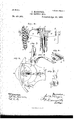
- Fig. 3 is an enlargedsection of a portion of the mill, showing the spring F and connections.
- Fig. 4. is a, plan of same, showing also plates J.
- Fig.5 is a perspective of casting G.
- Fig. 6 is a perspective of spring.
- Fig. 7 is a perspective of weai'ingplate H.
- Fig. 8 is a perspective of plate J.
- A is a pan through the center of which eX- tends the drive shaft B, to 'the top of which is connected the driver 0.
- tubular hangers or sleeves having trunnions d which are journaled in boxes in the outer ends of the driver, said hangers carrying the spindles or shafts e of the rollers E.
- the inner ends of the springs F are se-' cured in the following manner: To the central portion or hub of the driver 0 are secured, by a bolt at c, the castings G, which have grooved heads g, provided with an elongated slot, 9'. Into the grooved head g the inner end of a spring, F, is fitted, and is held in position by a bolt, f, passing through it and the elongated slot 9.
- This connection not only forms a safe and easy attachment for the springs, but also permits them to be adjusted. After the mill has been in use for atime the grinding shoes or rings'of the rollers wear, and it then becomes necessary to set the springs out farther to compensate for this wear.
- a wearing-plate, H having, as shown, a longitudinally grooved face.
- the end of the spring F is formed or provided with a wearing-knob, f, which fits in the grooved face of the wearing-plate, whereby it is held to its seat, and yet by working therein does not interfere at all with the independent movements of the spring and the pivoted hanger,
- the plates J are securedto stems j, which are fitted in the sockets K, formed with the driver 0.
- the curve of these plates is a reverse or ogee curve in horizontal section, and they are so arranged between the rollers asv to catch the one acted on by the traveling rollers, and which has an inward or central trend, and direct it outwardly toward the rim of the pan into the path of the rollers. They are further so arranged in point of position, one being farther toward the center than another, that the whole series will operate over the entire area of the pan bottom, so that the ore in all parts of the pan is kept constantly in motion and directed outwardly to the rim and into the path of the rollers.
- the directingplates are preferably made in two parts, the lower being removable to provide for the substitution of another when worn.
- the pan having the pivoted hangers and the series of centritugally-swinging rollers suspended from said hangers, in combination with springs secured by one end to the driver and having a wearing-knob on the other and the wearing-plates secured to the pivoted hangers and having grooved faces in which the wearing-knobs of the springs are fitted and play, substantially as herein described.
- the pan having the pivoted hangers, and the series of centrifugally-swinging rollers suspended from said hangers, in combination with the springs acting to throw the rollers outwardly, the grooved and slotted castings on the driver to which the inner ends of the springs are fitted, and the bolts adjustably securing said ends to the castings, the grooved wearing-plates secured to the pivoted hangers, and the wearing-knobs on the outer ends of the springs fitted to and playing in the grooved wearing-plates, substantially as herein described.
Landscapes
- Engineering & Computer Science (AREA)
- Food Science & Technology (AREA)
- Grinding Of Cylindrical And Plane Surfaces (AREA)
Description
(No'ModeL) 2 SheetsSheet 1.
J. McKENZIE. ORE GRINDING MILL.
Patented Apr. 11.3.
(No Model.)
- 2 Sheets-Sheet 2. J. MCKENZIE.
ORE GRINDING MILL. v No. 401,964. Patented Apr. 23,- 1889.
my. a
gy-i.
, F; I g' l. f I L9 E 1| W :iijj:
'NITED STATES PATENT Or-FIcE.
JOSEPH MCKENZIE, OF EL DORADO, CALIFORNIA, ASSIGNOR TO DE VITT l O. MORGAN, OF SAME PLACE.
ORE-GRINDING MILL.
SPECIFICATION forming part of Letters Patent No. 401,964, dated April 23, 1889.
7 Application filed November 16, 1888. Serial No. 291,039. (No model.)
To all whom, it may concern:
Be it known that I, JOSEPH MCKENZIE, of El Dorado, El Dorado county, State of California, have invented an Improvement in Ore- Grinding Mills; and I hereby declare the following to be a full, clear, and exact description of the same.
My invention relates to the class of oregrinding machines, and especially to that subclass known as centrifugal crushing-mills, in which the grinding-rollers are suspended from a rotating driver by a pivot or hinge connection and are adapted by centrifugal force to swing outwardly to the rim of the pan; and my invention consists in the constructions and combinations of devices which I a shall hereinafter fully describe and claim.
Referring to the accompanying drawings for a more complete explanation of niyinvention, Figure 1 is a vertical section of my improved grinding-mill. Fig. 2 is a plan view of the same. Fig. 3 is an enlargedsection of a portion of the mill, showing the spring F and connections. Fig. 4. is a, plan of same, showing also plates J. Fig.5 is a perspective of casting G. Fig. 6 is a perspective of spring.
F. Fig. 7 is a perspective of weai'ingplate H. Fig. 8 is a perspective of plate J.
A is a pan through the center of which eX- tends the drive shaft B, to 'the top of which is connected the driver 0.
D are tubular hangers or sleeves having trunnions d, which are journaled in boxes in the outer ends of the driver, said hangers carrying the spindles or shafts e of the rollers E.
The parts thus far-described are, essentially, those at present in use, and it will be seen that by rotating the shaft B the rollers are carried around, and, being suspended by pivots above, they swing outwardly by centrifugal force against the rim of pan A and grind the ore against said rim; but this force is not of sufficient certainty to overcome the difficulties in the way of the perfect operation of the rollers, for it often happens that a piece of ore will swerve a roller from its course, and it takes a few moments to have it return to its work. Then, again, as the rollers do not act constantly against the rim of the pan their shoes are apt to be worn unevenlyJ To overcome these disadvantages, I
employ the springs F, secured at one end in a manner I shall presently describe to the driver and bearing at their other end through the intervention of a wearing-plate against the pivoted hangers D, which carry the rollers. These springs hold the rollers out to their work positively, and yet allow them to yield sufficiently according to circumstances; but after yielding for any cause they are thrown out again immediately and with certainty, and the operation does not have to depend on centrifugal force alone.
The inner ends of the springs F are se-' cured in the following manner: To the central portion or hub of the driver 0 are secured, by a bolt at c, the castings G, which have grooved heads g, provided with an elongated slot, 9'. Into the grooved head g the inner end of a spring, F, is fitted, and is held in position by a bolt, f, passing through it and the elongated slot 9. This connection not only forms a safe and easy attachment for the springs, but also permits them to be adjusted. After the mill has been in use for atime the grinding shoes or rings'of the rollers wear, and it then becomes necessary to set the springs out farther to compensate for this wear. ily effected by loosening the bolts f and sliding the springs along to proper position and then tightening said bolts up again. To avoid wear 011 the lower ends of the springs, I bolt to the inner side of the pivoted hanger a wearing-plate, H, having, as shown, a longitudinally grooved face. The end of the spring F is formed or provided with a wearing-knob, f, which fits in the grooved face of the wearing-plate, whereby it is held to its seat, and yet by working therein does not interfere at all with the independent movements of the spring and the pivoted hanger,
This adjustment of the springs is read- The plates J are securedto stems j, which are fitted in the sockets K, formed with the driver 0. The curve of these plates is a reverse or ogee curve in horizontal section, and they are so arranged between the rollers asv to catch the one acted on by the traveling rollers, and which has an inward or central trend, and direct it outwardly toward the rim of the pan into the path of the rollers. They are further so arranged in point of position, one being farther toward the center than another, that the whole series will operate over the entire area of the pan bottom, so that the ore in all parts of the pan is kept constantly in motion and directed outwardly to the rim and into the path of the rollers. The directingplates are preferably made in two parts, the lower being removable to provide for the substitution of another when worn.
-I-Iaving thus described my invention, what I claim as new, and desire to secure by Letters Patent, is
1. In an ore-grinding mill, the pan, the rotating driver having the pivoted hangers and the series of centritugally-swinging rollers suspended from said hangers, in combination with springs secured by one end to the driver and having a wearing-knob on the other and the wearing-plates secured to the pivoted hangers and having grooved faces in which the wearing-knobs of the springs are fitted and play, substantially as herein described.
2. In an ore-grinding mill, the pan, the rotating driver having the pivoted hangers, and the series of centrifugally-swinging rollers suspended from said hangers, in combination with the springs acting to throw the rollers outwardly, the grooved and slotted castings on the driver to which the inner ends of the springs are fitted, and the bolts adjustably securing said ends to the castings, the grooved wearing-plates secured to the pivoted hangers, and the wearing-knobs on the outer ends of the springs fitted to and playing in the grooved wearing-plates, substantially as herein described.
In witness whereof I have hereunto set my hand.
JOSEPH MCKENZIE.
\Vitnesses:
L. O. BEEM. R. T. MoRNDoN.
Publications (1)
| Publication Number | Publication Date |
|---|---|
| US401964A true US401964A (en) | 1889-04-23 |
Family
ID=2470920
Family Applications (1)
| Application Number | Title | Priority Date | Filing Date |
|---|---|---|---|
| US401964D Expired - Lifetime US401964A (en) | mckenzie |
Country Status (1)
| Country | Link |
|---|---|
| US (1) | US401964A (en) |
-
0
- US US401964D patent/US401964A/en not_active Expired - Lifetime
Similar Documents
| Publication | Publication Date | Title |
|---|---|---|
| US401964A (en) | mckenzie | |
| US303125A (en) | Rock-pulverizer | |
| US475284A (en) | Charles e | |
| US1386132A (en) | Soil-pulverizer | |
| US556466A (en) | Crushing-mill | |
| US469145A (en) | Samuel hughes | |
| US387257A (en) | Signoes to the | |
| US359586A (en) | Machine for reducing wheat and analogous grain | |
| US681950A (en) | Hinge-pin. | |
| US1020092A (en) | Grinding-mill. | |
| US415941A (en) | Gideon frisbee | |
| US857940A (en) | Rock-crusher. | |
| US524536A (en) | Land-roller | |
| US111277A (en) | Improvement in millstone-drivers | |
| US644886A (en) | Sickle-bar adjuster. | |
| US305320A (en) | Roller mill | |
| US67914A (en) | russell | |
| US723322A (en) | Spring-saddle and driving-box. | |
| US698441A (en) | Grinding-mill. | |
| US119783A (en) | Improvement in flour-bolts | |
| US141699A (en) | Improvement in axle-boxes and sleeves for vehicle-wheels | |
| US493381A (en) | Mining-machine | |
| US270531A (en) | Edwaed m | |
| US122827A (en) | Improvement in grist-mills | |
| US142809A (en) | Improvement in tramming-bolts for grinding-mills |