US3976849A - Telephone wiring tester - Google Patents
Telephone wiring tester Download PDFInfo
- Publication number
- US3976849A US3976849A US05/601,048 US60104875A US3976849A US 3976849 A US3976849 A US 3976849A US 60104875 A US60104875 A US 60104875A US 3976849 A US3976849 A US 3976849A
- Authority
- US
- United States
- Prior art keywords
- contacts
- tip
- jack
- telephone line
- voltage
- Prior art date
- Legal status (The legal status is an assumption and is not a legal conclusion. Google has not performed a legal analysis and makes no representation as to the accuracy of the status listed.)
- Expired - Lifetime
Links
Images
Classifications
-
- H—ELECTRICITY
- H04—ELECTRIC COMMUNICATION TECHNIQUE
- H04M—TELEPHONIC COMMUNICATION
- H04M3/00—Automatic or semi-automatic exchanges
- H04M3/22—Arrangements for supervision, monitoring or testing
- H04M3/26—Arrangements for supervision, monitoring or testing with means for applying test signals or for measuring
- H04M3/28—Automatic routine testing ; Fault testing; Installation testing; Test methods, test equipment or test arrangements therefor
- H04M3/30—Automatic routine testing ; Fault testing; Installation testing; Test methods, test equipment or test arrangements therefor for subscriber's lines, for the local loop
-
- H—ELECTRICITY
- H04—ELECTRIC COMMUNICATION TECHNIQUE
- H04M—TELEPHONIC COMMUNICATION
- H04M1/00—Substation equipment, e.g. for use by subscribers
- H04M1/24—Arrangements for testing
Definitions
- This invention relates to telephone line testing devices, and more particularly to a portable testing unit which can be employed in testing the wiring connections for a telephone handset of the type employing a multiple-conductor plug received in a mating jack in the handset for connecting the handset to the telephone lines.
- a main object of the invention is to provide a novel and improved telephone line test unit which is very compact in size, which is easy to use, and which provides reliable visual indications as to the proper connections and line voltages of a telephone installation.
- a further object of the invention is to provide an improved test device to check for the presence of a minimum voltage of the correct polarity between the tip and ring line conductors of a telephone installation and also to check for the presence of a proper a.c. lamp voltage between ground and the lamp lead on a modular jack type telephone installations, the test device being usable without requiring the use of tools, providing immediate and visible indications, and giving indications showing the presence of a minimum d.c. voltage of correct polarity between the tip and ring line conductors and establishing the presence of proper a.c. voltage between the ground and lamp line conductors of the installation.
- a still further object of the invention is to provide a compact and inexpensive telephone line testing device usable by telephone installers and similar personnel for testing the integrity of wiring connections for telephone installations, the device involving relatively few components, being light in weight, being durable in construction, being small enough to carry in a user's pocket, and requiring no batteries.
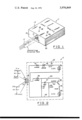
- FIG. 1 is a perspective view of a telephone line testing device constructed in accordance with the present invention, and showing how a conventional telephone handset line plug can be connected to the device for testing the associated telephone lines.
- FIG. 2 is a wiring diagram showing the electrical connections of the testing device of FIG. 1.
- the test unit 11 generally designates an improved test unit constructed in accordance with the present invention.
- the test unit 11 comprises a generally rectangular housing 25 provided with a four-terminal input jack 12 centrally mounted in one end wall 13 of the housing.
- the top wall 14 of the housing is formed with apertures 15 and 16 through which respectively project the top ends of conventional L.E.D. (light-emitting-diodes) D 5 and D 3 mounted on an insulating board, not shown, suitably secured in the housing.
- the input jack 12 is adapted to receive the standard four-terminal plug 17 used to connect the associated telephone wiring to a telephone handset in modular telephone installations of the type wherein the handset is provided with a dial lamp as well as with the normal receiver-transmitter equipment.
- the test unit 11 can be readily substituted for a handset by removing the line plug 17 from the handset and inserting the plug 17 into the test unit jack 12.
- the jack 12 is provided with the contact elements 18, 19, 20 and 21 corresponding respectively to the tip (green wire), ring (red wire), and dial lamp a.c. (yellow and black wires) input conductors of the 4-wire line cable cord connected to a terminal plug 17.
- the contact elements 18 and 19 are connected to a series circuit comprising a diode D 1 , which may be of the 1N4005 type, a zener diode D 2 , which may be of the 1N4744 type, a resistor R 1 , which may have a resistance of about 1200 ohms, and light-emitting diode D 3 .
- the contact element 20 is connected through a diode D 4 , which may be of the 1N4005 type, and a wire 22 to the collector of a transistor Q 1 , which may be of the 2N4401 type.
- a d.c.-blocking capacitor C 1 which may have a capacitance of about 10 mfd., is connected between wire 22 and a wire 24 connected to the base of transistor Q 1 .
- the emitter of transistor Q 1 is connected through a resistor R 4 , which may have a value of about 220 ohms, and the light-emitting diode D 5 to a return wire 23, which is connected to the contact element 21.
- a resistor R 3 of about 1000 ohms resistance is connected between wire 22 and wire 23, and a resistor R 2 of about 3300 ohms resistance is connected between the transistor base wire 24 and the return wire 23.
- the test device 11 is substituted for the telephone handset when it is intended to check for the presence of a minimum d.c. voltage of the correct polarity between the incoming tip and ring line wires and also at the same time to check for the presence of correct a.c. voltage between the incoming station ground (yellow wire) and "lamp" (black wire) line wires.
- the L.E.D. indicators D 3 and D 5 are provided to give a visual indication of these two conditions. If the d.c. voltage at contacts 18, 19 is not sufficient or is of the wrong polarity, the tip/ring indicator D 3 will not light.
- the tip contact element 18 has to be positive and the d.c. voltage has to exceed 18 v. (the conduction voltage of zener diode D 2 is about 15 v.) for the L.E.D. indicator D 3 to light.
- the tip/ring indicator D 3 will not light, since zener diode D 2 will not conduct.
- the a.c. amplifier circuit connected to contact elements 21, 20 is utilized.
- the L.E.D. indicator D 5 labelled "lamp” will illuminate if there is 10 to 18 v.a.c. present. If there is less than 10 v.a.c. present, the indicator D 5 will be dim.
- the amplifier circuit will not respond to d.c. voltage.
- the "lamp" indicator D 5 will not illuminate.
- the diode D 1 establishes the polarity necessary on the "tip" contact 18, namely, positive.
- Zener diode D 2 establishes the minimum voltage for the L.E.D. indicator D 3 to illuminate.
- Resistor R 1 prevents excessive current from flowing in this circuit when it is connected across a short loop.
- Zener diode D 2 having a zener voltage of 15 volts, prevents a.c. voltages in the range of 10 to below 18 volts from turning on the tip/ring L.E.D. indicator D 3 .
- D 4 In simultaneously checking for the presence of a proper a.c. voltage, D 4 establishes the correct polarity for transistor Q 1 to operate.
- contact element 20 goes positive with respect to contact element 21, D 4 conducts, placing a positive potential on the collector of transistor Q 1 ; also a positive pulse is coupled through capacitor C 1 to the base of transistor Q 1 , allowing Q 1 to conduct current through resistor R 4 , L.E.D. indicator D 5 and through return wire 23 to contact element 21.
- diode D 4 blocks current from flowing and prevents a back bias from being applied to transistor Q 1 .
- transistor Q 1 responds only briefly, due to the positive spike coupled through capacitor C 1 , allowing indicator D 5 to flicker. Transistor Q 1 does not sustain current flow due to the d.c. blocking action of capacitor C 1 .
- the simultaneous illumination of both L.E.D. indicators D 3 and D 5 shows that the line wires at the input are properly connected and carry correct d.c. and a.c. voltages. Failure of only D 3 to light will indicate improper polarity of the tip/ring line wires or insufficient d.c. voltage on these wires. Failure of only D 5 to light will indicate lack of a.c. voltage on the "lamp" (yellow and black) line wires, whereas if D 5 only lights dimly it indicates insufficient a.c. voltage. Failure of both D 3 and D 5 to light indicates either that the d.c. and a.c. line voltages are absent or that the tip ring line conductors have been interchanged with the 10 volt a.c. line conductors.
Abstract
A test unit for testing the wiring connections in modular telephone installations. The unit consists of a housing with an input jack to receive the standard plug used to connect the telephone wiring to a handset. The jack has four terminals, one pair corresponding to the green and red(tip-ring) line wires, and the other pair corresponding to the yellow and black (ground and lamp a.c.) line wires. The tip-ring terminals are connected in the housing through a first diode, a Zener diode and a resistor to a "tip-ring" L.E.D. The a.c. terminals are connected in the housing to a "lamp" L.E.D. through a diode and a transistor, controlled by a network including a blocking capacitor. When the telephone line plug is inserted in the test unit jack, the "tip-ring" L.E.D. will light only if the "tip-ring" line voltage is correct in magnitude and polarity, and the tip ring line conductors have not been interchanged with the a.c. line conductors. The "lamp" L.E.D. will light to indicate proper a.c. voltage on the a.c. line conductors. If the a.c. voltage is too low the "lamp" L.E.D. will be dim. The "lamp" L.E.D. will not light if the a.c. line conductors carry d.c. voltage.
Description
This invention relates to telephone line testing devices, and more particularly to a portable testing unit which can be employed in testing the wiring connections for a telephone handset of the type employing a multiple-conductor plug received in a mating jack in the handset for connecting the handset to the telephone lines.
A main object of the invention is to provide a novel and improved telephone line test unit which is very compact in size, which is easy to use, and which provides reliable visual indications as to the proper connections and line voltages of a telephone installation.
A further object of the invention is to provide an improved test device to check for the presence of a minimum voltage of the correct polarity between the tip and ring line conductors of a telephone installation and also to check for the presence of a proper a.c. lamp voltage between ground and the lamp lead on a modular jack type telephone installations, the test device being usable without requiring the use of tools, providing immediate and visible indications, and giving indications showing the presence of a minimum d.c. voltage of correct polarity between the tip and ring line conductors and establishing the presence of proper a.c. voltage between the ground and lamp line conductors of the installation.
A still further object of the invention is to provide a compact and inexpensive telephone line testing device usable by telephone installers and similar personnel for testing the integrity of wiring connections for telephone installations, the device involving relatively few components, being light in weight, being durable in construction, being small enough to carry in a user's pocket, and requiring no batteries.
Further objects and advantages of the invention will become apparent from the following description and claims, and from the accompanying drawings, wherein:
FIG. 1 is a perspective view of a telephone line testing device constructed in accordance with the present invention, and showing how a conventional telephone handset line plug can be connected to the device for testing the associated telephone lines.
FIG. 2 is a wiring diagram showing the electrical connections of the testing device of FIG. 1.
Referring to the drawings, 11 generally designates an improved test unit constructed in accordance with the present invention. The test unit 11 comprises a generally rectangular housing 25 provided with a four-terminal input jack 12 centrally mounted in one end wall 13 of the housing. The top wall 14 of the housing is formed with apertures 15 and 16 through which respectively project the top ends of conventional L.E.D. (light-emitting-diodes) D5 and D3 mounted on an insulating board, not shown, suitably secured in the housing. The input jack 12 is adapted to receive the standard four-terminal plug 17 used to connect the associated telephone wiring to a telephone handset in modular telephone installations of the type wherein the handset is provided with a dial lamp as well as with the normal receiver-transmitter equipment. Thus, the test unit 11 can be readily substituted for a handset by removing the line plug 17 from the handset and inserting the plug 17 into the test unit jack 12.
The jack 12 is provided with the contact elements 18, 19, 20 and 21 corresponding respectively to the tip (green wire), ring (red wire), and dial lamp a.c. (yellow and black wires) input conductors of the 4-wire line cable cord connected to a terminal plug 17.
The contact elements 18 and 19 are connected to a series circuit comprising a diode D1, which may be of the 1N4005 type, a zener diode D2, which may be of the 1N4744 type, a resistor R1, which may have a resistance of about 1200 ohms, and light-emitting diode D3.
The contact element 20 is connected through a diode D4, which may be of the 1N4005 type, and a wire 22 to the collector of a transistor Q1, which may be of the 2N4401 type. A d.c.-blocking capacitor C1, which may have a capacitance of about 10 mfd., is connected between wire 22 and a wire 24 connected to the base of transistor Q1. The emitter of transistor Q1 is connected through a resistor R4, which may have a value of about 220 ohms, and the light-emitting diode D5 to a return wire 23, which is connected to the contact element 21. A resistor R3, of about 1000 ohms resistance is connected between wire 22 and wire 23, and a resistor R2 of about 3300 ohms resistance is connected between the transistor base wire 24 and the return wire 23.
The test device 11 is substituted for the telephone handset when it is intended to check for the presence of a minimum d.c. voltage of the correct polarity between the incoming tip and ring line wires and also at the same time to check for the presence of correct a.c. voltage between the incoming station ground (yellow wire) and "lamp" (black wire) line wires. The L.E.D. indicators D3 and D5 are provided to give a visual indication of these two conditions. If the d.c. voltage at contacts 18, 19 is not sufficient or is of the wrong polarity, the tip/ring indicator D3 will not light. The tip contact element 18 has to be positive and the d.c. voltage has to exceed 18 v. (the conduction voltage of zener diode D2 is about 15 v.) for the L.E.D. indicator D3 to light.
If a condition exists where the tip and ring conductors have been interchanged in the line wiring with the 10 v.a.c. line conductors, the tip/ring indicator D3 will not light, since zener diode D2 will not conduct.
To detect the presence of 10 v.a.c. between the "lamp" lead (black wire) and the station ground lead (yellow wire), the a.c. amplifier circuit connected to contact elements 21, 20 is utilized. The L.E.D. indicator D5, labelled "lamp" will illuminate if there is 10 to 18 v.a.c. present. If there is less than 10 v.a.c. present, the indicator D5 will be dim. The amplifier circuit will not respond to d.c. voltage.
Therefore, if a condition exists where the tip and ring line conductors have been interchanged with the 10 v.a.c. line conductors, the "lamp" indicator D5 will not illuminate.
In operating the test device, as above described, the diode D1 establishes the polarity necessary on the "tip" contact 18, namely, positive. Zener diode D2 establishes the minimum voltage for the L.E.D. indicator D3 to illuminate. Resistor R1 prevents excessive current from flowing in this circuit when it is connected across a short loop. Zener diode D2, having a zener voltage of 15 volts, prevents a.c. voltages in the range of 10 to below 18 volts from turning on the tip/ring L.E.D. indicator D3.
In simultaneously checking for the presence of a proper a.c. voltage, D4 establishes the correct polarity for transistor Q1 to operate. When contact element 20 goes positive with respect to contact element 21, D4 conducts, placing a positive potential on the collector of transistor Q1 ; also a positive pulse is coupled through capacitor C1 to the base of transistor Q1, allowing Q1 to conduct current through resistor R4, L.E.D. indicator D5 and through return wire 23 to contact element 21. When the a.c. cycle reverses, diode D4 blocks current from flowing and prevents a back bias from being applied to transistor Q1.
In the event that there is a d.c. voltage between contact elements 20, 21 of the correct polarity to cause diode D4 to conduct, transistor Q1 responds only briefly, due to the positive spike coupled through capacitor C1, allowing indicator D5 to flicker. Transistor Q1 does not sustain current flow due to the d.c. blocking action of capacitor C1.
Thus, when the test device 11 is substituted for the handset, as above described, the simultaneous illumination of both L.E.D. indicators D3 and D5 shows that the line wires at the input are properly connected and carry correct d.c. and a.c. voltages. Failure of only D3 to light will indicate improper polarity of the tip/ring line wires or insufficient d.c. voltage on these wires. Failure of only D5 to light will indicate lack of a.c. voltage on the "lamp" (yellow and black) line wires, whereas if D5 only lights dimly it indicates insufficient a.c. voltage. Failure of both D3 and D5 to light indicates either that the d.c. and a.c. line voltages are absent or that the tip ring line conductors have been interchanged with the 10 volt a.c. line conductors.
While a specific embodiment of an improved telephone line test unit has been disclosed in the foregoing description, it will be understood that various modifications within the spirit of the invention may occur to those skilled in the art. Therefore it is intended that no limitations be placed on the invention except as defined by the scope of the appended claims.
Claims (8)
1. In combination with a four-terminal plug for connection of a telephone handset employing d.c. tip-ring voltage and a.c. lamp voltage coupled over d.c. and a.c. lines respectively, a telephone line testing device for assuring proper connections of said voltages to said lines comprising a support provided with a four-contact jack adapted to receive the four-terminal handset plug connected to said d.c. and a.c. lines, said jack having two d.c. contacts and two a.c. contacts, a series circuit branch on said support including a first rectifier and a first electrical light-emitting device, circuit means connecting said series circuit branch to the two d.c. contacts, a second circuit branch on said support comprising an a.c. amplifier including a d.c.-blocking input capacitor, a second electrical light-emitting device connected to the output of the amplifier, and a second rectifier connected in series with the input of the amplifier, and circuit means connecting said second circuit branch to the two a.c. jack contacts.
2. The telephone line testing device of claim 1, and a zener diode connected in said series circuit branch.
3. The telephone line testing device of claim 2, and wherein said zener diode has a conduction voltage of approximately 15 volts.
4. The telephone line testing device of claim 2, and wherein said zener diode is connected between said first rectifier and said first electrical light-emitting device.
5. A telephone line testing device comprising a support provided with a four-contact jack adapted to receive a four-terminal handset plug connected to the telephone lines, said jack having two d.c. contacts and two a.c. contacts, a series circuit branch on said support including a first rectifier and a first electrical light-emitting device, circuit means connecting said series circuit branch to the two d.c. contacts, a second circuit branch on said support comprising an a.c. amplifier including a d.c.-blocking input capacitor, a second electrical light-emitting device connected to the output of the amplifier, and a second rectifier connected in series with the input of the amplifier, and circuit means connecting said second circuit branch to the two a.c. jack contacts, and wherein said amplifier comprises a transistor, the output of said second rectifier being connected through said blocking capacitor to the base of the transistor and to the collector of the transistor, the second electrical light emitting device being connected in the emitter circuit of the transistor.
6. The telephone line testing device of claim 5, and wherein said series branch includes a zener diode connected between said first rectifier and said first electrical light-emitting device.
7. The telephone line testing device of claim 6, and wherein said zener diode has a conduction voltage of approximately 15 volts.
8. The telephone line testing device of claim 7, and wherein said electrical light-emitting devices comprise light-emitting diodes.
Priority Applications (1)
| Application Number | Priority Date | Filing Date | Title |
|---|---|---|---|
| US05/601,048 US3976849A (en) | 1975-08-01 | 1975-08-01 | Telephone wiring tester |
Applications Claiming Priority (1)
| Application Number | Priority Date | Filing Date | Title |
|---|---|---|---|
| US05/601,048 US3976849A (en) | 1975-08-01 | 1975-08-01 | Telephone wiring tester |
Publications (1)
| Publication Number | Publication Date |
|---|---|
| US3976849A true US3976849A (en) | 1976-08-24 |
Family
ID=24406031
Family Applications (1)
| Application Number | Title | Priority Date | Filing Date |
|---|---|---|---|
| US05/601,048 Expired - Lifetime US3976849A (en) | 1975-08-01 | 1975-08-01 | Telephone wiring tester |
Country Status (1)
| Country | Link |
|---|---|
| US (1) | US3976849A (en) |
Cited By (35)
| Publication number | Priority date | Publication date | Assignee | Title |
|---|---|---|---|---|
| US4186283A (en) * | 1978-05-22 | 1980-01-29 | Perkins Research & Manufacturing Co., Inc. | Test set |
| US4209671A (en) * | 1977-08-02 | 1980-06-24 | Coil Sales & Manufacturing Company | Method and apparatus for testing the tip-ring polarity of telephone receptacles connected in parallel to a non-working pair |
| US4214132A (en) * | 1978-01-24 | 1980-07-22 | Kelso Thomas W | Testing tools for modular telephone system |
| US4368363A (en) * | 1981-05-11 | 1983-01-11 | Tii Industries Inc. | Audible line test termination device |
| US4373120A (en) * | 1981-01-13 | 1983-02-08 | Tii Industries Inc. | Line test termination device |
| DE3148740A1 (en) * | 1981-12-05 | 1983-06-09 | Fritz Kuke Kg, 1000 Berlin | TERMINATION FOR TELEPHONE LINES |
| US4388501A (en) * | 1981-05-11 | 1983-06-14 | Tii Industries Inc. | Audio-visual line test termination device |
| EP0123459A1 (en) * | 1983-04-21 | 1984-10-31 | Northern Telecom Limited | Loop test circuit |
| USRE31728E (en) * | 1978-05-22 | 1984-11-06 | Perkins Research & Manufacturing Co. | Test set |
| US4533864A (en) * | 1983-04-21 | 1985-08-06 | Northern Telecom Limited | Test instrument with flexibly connected head |
| US4544807A (en) * | 1983-06-13 | 1985-10-01 | Sers Gilbert L | Fault detector test instrument |
| US4564728A (en) * | 1984-04-13 | 1986-01-14 | Comus International, Inc. | Apparatus for testing a telephone line |
| US4581494A (en) * | 1984-10-09 | 1986-04-08 | James A. Mayberry | Telephone interface-test device |
| US4600810A (en) * | 1984-09-07 | 1986-07-15 | Amp Incorporated | Telephone line tester |
| JPS61177850A (en) * | 1985-02-04 | 1986-08-09 | イリノイ ツール ワークス インコーポレイテツド | Jack-socket type telephone line tester |
| JPS61182352A (en) * | 1985-02-04 | 1986-08-15 | イリノイ ツール ワークス インコーポレイテツド | Telephone tester with inline switch |
| US4679224A (en) * | 1985-12-02 | 1987-07-07 | Keptel, Inc. | Telephone line testing circuit |
| US4701699A (en) * | 1985-09-04 | 1987-10-20 | General Telephone Company Of Indiana | Telephone station testing apparatus |
| GB2195512A (en) * | 1986-09-10 | 1988-04-07 | Emp Systems Limited | Telephone line tester |
| US4756017A (en) * | 1987-03-23 | 1988-07-05 | Golden State Communications Service, Inc. | Telephone test device |
| US4827498A (en) * | 1984-08-17 | 1989-05-02 | Ross James W | Telephone line and instrument tester |
| US4843326A (en) * | 1987-08-17 | 1989-06-27 | Smythe Robert H | Electrical testing device for the power input to automobile telephone installations |
| US4901003A (en) * | 1987-10-30 | 1990-02-13 | Northern Telecom Limited | Telecommunications wiring test apparatus and method including two color display indicating correct wiring |
| US4968929A (en) * | 1987-04-18 | 1990-11-06 | Heidelberger Druckmaschinen Ag | Plug connector coding system for electric cables |
| US4969179A (en) * | 1990-01-09 | 1990-11-06 | Edward Kanare | Telephone line monitoring circuit for providing a visual and auditory signal if the telephone line becomes inoperative |
| US5056131A (en) * | 1990-10-29 | 1991-10-08 | Edward Kanare | Telephone line monitoring circuitry and apparatus |
| WO1995032575A3 (en) * | 1994-05-17 | 1996-02-08 | British Telecomm | Network termination equipment |
| US5513373A (en) * | 1994-03-21 | 1996-04-30 | Motorola, Inc. | Apparatus using three light emitting diodes (LEDs) and a transistor for indicating whether there is an overtermination undertermination, or power termination of peripheral devices |
| US5832076A (en) * | 1996-08-07 | 1998-11-03 | Transcrypt International, Inc. | Apparatus and method for determining the presence and polarity of direct current bias voltage for microphones in telephone sets |
| US5838804A (en) * | 1996-08-07 | 1998-11-17 | Transcrypt International, Inc. | Apparatus and method for providing proper microphone DC bias current and load resistance for a telephone |
| US5960060A (en) * | 1997-08-19 | 1999-09-28 | J. V. Technologies, Inc. | Line tester for coin-operated telephones |
| US6055299A (en) * | 1998-03-19 | 2000-04-25 | Lucent Technologies Inc. | Connector block with built-in array test feature |
| US20050069093A1 (en) * | 2003-09-26 | 2005-03-31 | Qwest Communications International Inc. | Systems and methods for determining the status of telephone lines |
| US7301432B1 (en) | 2005-01-11 | 2007-11-27 | Tii Network Technologies, Inc. | Fusing terminal device |
| US20070296420A1 (en) * | 2005-04-05 | 2007-12-27 | Dell Products L.P. | Device For Testing Connectivity Of A Connector Including Spring Contact Pins |
Citations (4)
| Publication number | Priority date | Publication date | Assignee | Title |
|---|---|---|---|---|
| US2367013A (en) * | 1942-03-24 | 1945-01-09 | American Telephone & Telegraph | Insulation test set |
| US3711661A (en) * | 1971-02-05 | 1973-01-16 | J Garrett | Distributing terminal assembly test apparatus |
| US3870836A (en) * | 1973-02-02 | 1975-03-11 | Daimei Tsushin Sangyo Kabushik | Portable tester for telephone subscriber lines |
| US3922507A (en) * | 1974-03-04 | 1975-11-25 | Arthur N White | Distributing terminal assembly test apparatus |
-
1975
- 1975-08-01 US US05/601,048 patent/US3976849A/en not_active Expired - Lifetime
Patent Citations (4)
| Publication number | Priority date | Publication date | Assignee | Title |
|---|---|---|---|---|
| US2367013A (en) * | 1942-03-24 | 1945-01-09 | American Telephone & Telegraph | Insulation test set |
| US3711661A (en) * | 1971-02-05 | 1973-01-16 | J Garrett | Distributing terminal assembly test apparatus |
| US3870836A (en) * | 1973-02-02 | 1975-03-11 | Daimei Tsushin Sangyo Kabushik | Portable tester for telephone subscriber lines |
| US3922507A (en) * | 1974-03-04 | 1975-11-25 | Arthur N White | Distributing terminal assembly test apparatus |
Cited By (41)
| Publication number | Priority date | Publication date | Assignee | Title |
|---|---|---|---|---|
| US4209671A (en) * | 1977-08-02 | 1980-06-24 | Coil Sales & Manufacturing Company | Method and apparatus for testing the tip-ring polarity of telephone receptacles connected in parallel to a non-working pair |
| US4214132A (en) * | 1978-01-24 | 1980-07-22 | Kelso Thomas W | Testing tools for modular telephone system |
| USRE31728E (en) * | 1978-05-22 | 1984-11-06 | Perkins Research & Manufacturing Co. | Test set |
| US4186283A (en) * | 1978-05-22 | 1980-01-29 | Perkins Research & Manufacturing Co., Inc. | Test set |
| US4373120A (en) * | 1981-01-13 | 1983-02-08 | Tii Industries Inc. | Line test termination device |
| US4368363A (en) * | 1981-05-11 | 1983-01-11 | Tii Industries Inc. | Audible line test termination device |
| US4388501A (en) * | 1981-05-11 | 1983-06-14 | Tii Industries Inc. | Audio-visual line test termination device |
| DE3148740A1 (en) * | 1981-12-05 | 1983-06-09 | Fritz Kuke Kg, 1000 Berlin | TERMINATION FOR TELEPHONE LINES |
| US4533864A (en) * | 1983-04-21 | 1985-08-06 | Northern Telecom Limited | Test instrument with flexibly connected head |
| US4513179A (en) * | 1983-04-21 | 1985-04-23 | Northern Telecom Limited | Loop test circuit |
| EP0123459A1 (en) * | 1983-04-21 | 1984-10-31 | Northern Telecom Limited | Loop test circuit |
| US4544807A (en) * | 1983-06-13 | 1985-10-01 | Sers Gilbert L | Fault detector test instrument |
| US4564728A (en) * | 1984-04-13 | 1986-01-14 | Comus International, Inc. | Apparatus for testing a telephone line |
| US4827498A (en) * | 1984-08-17 | 1989-05-02 | Ross James W | Telephone line and instrument tester |
| US4600810A (en) * | 1984-09-07 | 1986-07-15 | Amp Incorporated | Telephone line tester |
| US4581494A (en) * | 1984-10-09 | 1986-04-08 | James A. Mayberry | Telephone interface-test device |
| JPS61177850A (en) * | 1985-02-04 | 1986-08-09 | イリノイ ツール ワークス インコーポレイテツド | Jack-socket type telephone line tester |
| JPS61182352A (en) * | 1985-02-04 | 1986-08-15 | イリノイ ツール ワークス インコーポレイテツド | Telephone tester with inline switch |
| US4626633A (en) * | 1985-02-04 | 1986-12-02 | Illinois Tool Works, Inc. | In-line switched telephone line tester |
| US4701699A (en) * | 1985-09-04 | 1987-10-20 | General Telephone Company Of Indiana | Telephone station testing apparatus |
| US4679224A (en) * | 1985-12-02 | 1987-07-07 | Keptel, Inc. | Telephone line testing circuit |
| GB2195512A (en) * | 1986-09-10 | 1988-04-07 | Emp Systems Limited | Telephone line tester |
| US4756017A (en) * | 1987-03-23 | 1988-07-05 | Golden State Communications Service, Inc. | Telephone test device |
| US4968929A (en) * | 1987-04-18 | 1990-11-06 | Heidelberger Druckmaschinen Ag | Plug connector coding system for electric cables |
| US4843326A (en) * | 1987-08-17 | 1989-06-27 | Smythe Robert H | Electrical testing device for the power input to automobile telephone installations |
| US4901003A (en) * | 1987-10-30 | 1990-02-13 | Northern Telecom Limited | Telecommunications wiring test apparatus and method including two color display indicating correct wiring |
| US4969179A (en) * | 1990-01-09 | 1990-11-06 | Edward Kanare | Telephone line monitoring circuit for providing a visual and auditory signal if the telephone line becomes inoperative |
| US5062131A (en) * | 1990-01-09 | 1991-10-29 | Edward Kanare | Telephone line monitoring circuit for providing a visual and auditory signal if the telephone line becomes inoperative |
| US5056131A (en) * | 1990-10-29 | 1991-10-08 | Edward Kanare | Telephone line monitoring circuitry and apparatus |
| US5513373A (en) * | 1994-03-21 | 1996-04-30 | Motorola, Inc. | Apparatus using three light emitting diodes (LEDs) and a transistor for indicating whether there is an overtermination undertermination, or power termination of peripheral devices |
| WO1995032575A3 (en) * | 1994-05-17 | 1996-02-08 | British Telecomm | Network termination equipment |
| US5841836A (en) * | 1994-05-17 | 1998-11-24 | British Telecommunications Public Limited Company | Network termination equipment |
| US5832076A (en) * | 1996-08-07 | 1998-11-03 | Transcrypt International, Inc. | Apparatus and method for determining the presence and polarity of direct current bias voltage for microphones in telephone sets |
| US5838804A (en) * | 1996-08-07 | 1998-11-17 | Transcrypt International, Inc. | Apparatus and method for providing proper microphone DC bias current and load resistance for a telephone |
| US5960060A (en) * | 1997-08-19 | 1999-09-28 | J. V. Technologies, Inc. | Line tester for coin-operated telephones |
| US6055299A (en) * | 1998-03-19 | 2000-04-25 | Lucent Technologies Inc. | Connector block with built-in array test feature |
| US20050069093A1 (en) * | 2003-09-26 | 2005-03-31 | Qwest Communications International Inc. | Systems and methods for determining the status of telephone lines |
| US7295655B2 (en) | 2003-09-26 | 2007-11-13 | Qwest Communications International Inc. | Systems and methods for determining the status of telephone lines |
| US7301432B1 (en) | 2005-01-11 | 2007-11-27 | Tii Network Technologies, Inc. | Fusing terminal device |
| US20070296420A1 (en) * | 2005-04-05 | 2007-12-27 | Dell Products L.P. | Device For Testing Connectivity Of A Connector Including Spring Contact Pins |
| US7397251B2 (en) * | 2005-04-05 | 2008-07-08 | Dell Products L.P. | Device for testing connectivity of a connector including spring contact pins |
Similar Documents
| Publication | Publication Date | Title |
|---|---|---|
| US3976849A (en) | Telephone wiring tester | |
| US6054849A (en) | Electrical testing device | |
| US5166970A (en) | Multi-conductor identifier with voice communication capability | |
| US4418312A (en) | Apparatus for testing multi-conductor cables | |
| US4600810A (en) | Telephone line tester | |
| US4829289A (en) | Static grounding and monitoring accessory | |
| EP0374224A1 (en) | Portable identifier apparatus for communication cables. | |
| US4827498A (en) | Telephone line and instrument tester | |
| US4533864A (en) | Test instrument with flexibly connected head | |
| US4373120A (en) | Line test termination device | |
| US4588862A (en) | Visual display network interface | |
| US4620070A (en) | Telephone line tester | |
| US4209671A (en) | Method and apparatus for testing the tip-ring polarity of telephone receptacles connected in parallel to a non-working pair | |
| US5640058A (en) | Kits for converting DC battery powered smoke detectors to AC power with battery back-up | |
| US4679224A (en) | Telephone line testing circuit | |
| EP0123459B1 (en) | Loop test circuit | |
| US4920555A (en) | Compact telephone line test apparatus | |
| US4544807A (en) | Fault detector test instrument | |
| US4369341A (en) | Customer line test termination device | |
| US4388501A (en) | Audio-visual line test termination device | |
| US4117264A (en) | Diode package for use with a central office connector module | |
| US5754624A (en) | Telephone line test kit | |
| US4368363A (en) | Audible line test termination device | |
| US4350849A (en) | Varying impedance line test termination device | |
| US4945555A (en) | Method and means for remote testing of unused telephone lines |
Legal Events
| Date | Code | Title | Description |
|---|---|---|---|
| AS | Assignment |
Owner name: MELCO LABS, INC., A CORP. OF WASH. Free format text: ASSIGNMENT OF ASSIGNORS INTEREST.;ASSIGNOR:MCINTOSH, ALEXANDER C.;REEL/FRAME:003991/0403 Effective date: 19820510 |
|
| AS | Assignment |
Owner name: TELZON INC., 14408 N.E. 20TH STREET, BELLEVUE, WAS Free format text: ASSIGNMENT OF ASSIGNORS INTEREST.;ASSIGNOR:MELCO LABS, INC.;REEL/FRAME:004470/0752 Effective date: 19850912 |