US395656A - Adolf jeenel - Google Patents
Adolf jeenel Download PDFInfo
- Publication number
- US395656A US395656A US395656DA US395656A US 395656 A US395656 A US 395656A US 395656D A US395656D A US 395656DA US 395656 A US395656 A US 395656A
- Authority
- US
- United States
- Prior art keywords
- drum
- chain
- barrel
- attached
- car
- Prior art date
- Legal status (The legal status is an assumption and is not a legal conclusion. Google has not performed a legal analysis and makes no representation as to the accuracy of the status listed.)
- Expired - Lifetime
Links
- 238000010276 construction Methods 0.000 description 1
- 230000036461 convulsion Effects 0.000 description 1
- 230000013707 sensory perception of sound Effects 0.000 description 1
- 230000035939 shock Effects 0.000 description 1
- 239000007858 starting material Substances 0.000 description 1
Images
Classifications
-
- B—PERFORMING OPERATIONS; TRANSPORTING
- B61—RAILWAYS
- B61D—BODY DETAILS OR KINDS OF RAILWAY VEHICLES
- B61D43/00—Devices for using the energy of the movements of the vehicles
Definitions
- My invention relates to improved means for starting tramway-cars, by which means the initial pull necessary to start the car is made much lighter and the vehicle moves much more easily without any jerk or shock.
- the nature of the invention consists in the combination, with the bottom of a tramwaycar and the'wheel and axle thereof, of a 1101- low revolublc drum or barrel mounted in bearings upon suitable brackets fastened to the bottom, of said car, a spiral spring placed within said drum or barrel and having one end attached to one of said brackets and the other end attached to the interior of said drum or barrel, a sprocket-wheel mounted upon the axle of said vehicle, a chain attached by one end to said drum, wound around said drum or barrel, passing over said sprocket-wheel, and extending under the bottom of said car far enough forwz'ird to be attached to a rope or chain, and a rope or chain one end of which is attached, as hereinbefore specified, to the end of said chain, extending forward over said sprocket-wheel from said drum or barrel and reaching far enough forward to be attached to the draft apparatus of the car, all for the purpose and in the way substantially as hcneinai'ter specified.
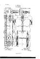
- Figure 1 is a longitudinal sectional view illustrating a part of the lower part of a car to slide on the guides i.
- FIG. 2 is a plan View of the same.
- Figs. 8, 4, 5, 6, and 7 are detail views illustrating various parts of my invention and parts of the accompanying mechanism.
- 1 indicates a drum orbarrel mounted upon hearings in the bracket H.
- This bracket is firmly attached to the bottom of the car by bolts or in any other convenient way.
- the drum or barrel b is hollow, and within it is coiled the spiral spring d, one end of which is attached to the bracket H and the other end to the interior of the drum or barrel 1).
- the periphery of this drum or barrel 1) is formed with two flanges, between which are a series of sprocket-teeth running almost around the periphery of said wheel.
- 9 designates a chain, one end of which is attached to the periphery of the said drum or barrel 1). This chain is wound, as illustrated, around the said drum or barrel, with its links engaging the sprocket-teeth.
- c designates a sprocket-wheel mounted on the axle of the car and rigidly attached thereto.
- the teeth of this wheel are inclined a little, so that it has very much the appearance of a ratchet.
- the chain c is so long that it passes forward beyond this sprocket-wheel c, engag ing the teeth thereof with its links in the usual and well-known way.
- a light car may be worked with only one barrel or drum, one spiral spring, one sprocketwheel, and one chain c, in. which case the rope or chain h is attached directly to the forward end of the one chain c.
- a chain, c attached by one end to the periphery of said drum or barrel Z), wound around said drum or barrel b, extending over and engaging the teeth.
- said sprocket-wheel with its links and reaching far enough forward to be attached to one end of the draw-bar g, and a like chain accompanied by a like sprocketwhcel and a like drum or barrel, both mounted like the said drum or barrel and sprocketwheel, and the drum or barrel being provided with a like spiral spring
- the said chain being in like manner attached to the other end of the draw-bar g, the chain or rope 72, attached by one end to the middle of said draw-bar g, reaching forward and attached to the drafthook n, the guides iand 1', attached to the bottom of said car, the stops m, 70, and 0, attached to the bottom of said car, the projection f of the said chain c, and the guide a, at-- tached to the bottom of said car, all substantially
Landscapes
- Engineering & Computer Science (AREA)
- Transportation (AREA)
- Mechanical Engineering (AREA)
- Transmissions By Endless Flexible Members (AREA)
- Devices For Conveying Motion By Means Of Endless Flexible Members (AREA)
Description
UNITE STATES PATENT rEicE.
ADOLF JEENEL, OF BRESLAU, PRUSSIA, GERMANY.
CAR-STARTER.
SPECIFICATION forming part of Letters Patent No. 395,656, dated January 1, 1889.
Application filed November 23, 1887. Serial No. 256,027. (No model.) Patented in Germany September 14,1887,No.42,565; in Belgium November 10, 1887, No. 79,486; in England November 11,1887, No. 15,396, and in Austria-Hungary March 26,
1888, No. 44,414 and No. 7,202.
To all whom it may concern.-
Be it known that I, ADOLF JEENEL, superreviser, a subject of the King of Prussia, residing at Breslau, in the Province of Silesia, of the Kingdom of Prussia,German Empire, have invented certain new and useful Improvements in Mechanism for Starting Tramway- (fars, (for which I have obtained the following patents: of Germany, No. 42,565, dated September 14, 1887; of Belgium, No. 79,486, dated November 10, 1887 of England, No. 15,896, dated November 11, 1887; of Austria- Hungary, Nos. 44,414 and 7 ,202, dated March 26, 1888,) of which the following is a specification.
My invention relates to improved means for starting tramway-cars, by which means the initial pull necessary to start the car is made much lighter and the vehicle moves much more easily without any jerk or shock.
The nature of the invention consists in the combination, with the bottom of a tramwaycar and the'wheel and axle thereof, of a 1101- low revolublc drum or barrel mounted in bearings upon suitable brackets fastened to the bottom, of said car, a spiral spring placed within said drum or barrel and having one end attached to one of said brackets and the other end attached to the interior of said drum or barrel, a sprocket-wheel mounted upon the axle of said vehicle, a chain attached by one end to said drum, wound around said drum or barrel, passing over said sprocket-wheel, and extending under the bottom of said car far enough forwz'ird to be attached to a rope or chain, and a rope or chain one end of which is attached, as hereinbefore specified, to the end of said chain, extending forward over said sprocket-wheel from said drum or barrel and reaching far enough forward to be attached to the draft apparatus of the car, all for the purpose and in the way substantially as hcneinai'ter specified.
The nature of the invention also consists in the details 01? combination and construction, substantially as illustratedin the drawings, hereinafter described, and suliisequently pointed out in the claims.
Figure 1 is a longitudinal sectional view illustrating a part of the lower part of a car to slide on the guides i.
with my invention applied. Fig. 2 is a plan View of the same. Figs. 8, 4, 5, 6, and 7 are detail views illustrating various parts of my invention and parts of the accompanying mechanism.
In the drawings, 1) indicates a drum orbarrel mounted upon hearings in the bracket H. This bracket is firmly attached to the bottom of the car by bolts or in any other convenient way. The drum or barrel b is hollow, and within it is coiled the spiral spring d, one end of which is attached to the bracket H and the other end to the interior of the drum or barrel 1). The periphery of this drum or barrel 1) is formed with two flanges, between which are a series of sprocket-teeth running almost around the periphery of said wheel. 9 designates a chain, one end of which is attached to the periphery of the said drum or barrel 1). This chain is wound, as illustrated, around the said drum or barrel, with its links engaging the sprocket-teeth.
c designates a sprocket-wheel mounted on the axle of the car and rigidly attached thereto. The teeth of this wheel are inclined a little, so that it has very much the appearance of a ratchet. The chain c is so long that it passes forward beyond this sprocket-wheel c, engag ing the teeth thereof with its links in the usual and well-known way. There are two of these chains 2, each provided with the accompanying mechanism just described, which chains and accompanying mechanism are placed one under each side of the car just within the wheels, as illustrated in Fig. 2. The front ends of these chains are fastened together by the draw-bar g, which is adapted To the middle of this draw-bar g is attached one end of the rope or chain h, which, extending forward, is attached by its other end to the draft-hook "a. Upon the side of the chain c is a projection, (designated by f of Fig. 7,) which may be a continuation of one of the connecting-rivets of the chain. This running upon the inclined bar or guide 6' lifts the links from out of engagement with the teeth of the sprocketwheel 0. When the car is standing still, the chain c is wound upon the drum or barrel, and the whole device is in the position illustrated in full lines in Fig. 2; but as soon as the horse begins to pull the draw-bar'g slides forward on the guides 'i, being drawn by the rope or chain 7b. This causes the chain c to unwind from the drum or barrel 1) and run over the sprocket-wheel c. This motion turns the sprocket-wheel c, and with it the axle and wheel of the vehicle, thereby giving the wheel a start. As soon as the projeetionf, running upon the inclined guide 6', has lifted the links of the chain c from out of engagement with the teeth of the sprocket-wheel c the wheel of the vehicle will be free to roll forward. This will occur at or before the time the draw-bar g, sliding forward, encounters the buifers 0, which limit its forward action, as illustrated in Fig. 2 in dotted lines. This motion. of the bar 9 may, however, be limited by the stop an or the stop 7:, if it be desirable, and the operation of the projection f arranged accordingly. As the spring (Z is wound one way in the drum or barrel Z) and the chain c is wound another way upon it, this unwinding of the chain to start will wind up the spring, and when the vehicle stops the spring will by its resilience return all the various parts of the mechanism to their original positions ready for another start. If, however, it be desirable, a light car may be worked with only one barrel or drum, one spiral spring, one sprocketwheel, and one chain c, in. which case the rope or chain h is attached directly to the forward end of the one chain c.
hat I claim as my invention, and desire to secure by Letters Patent, is
1. The combination, with the bottom of a tramway-car and the wheel and axle thereof, of a hollow revoluble drum or barrel mounted in bearings upon suitable brackets fastened to the bottom of said car, a spiral spring placed within said drum or barrel, having one end attached to one of said brackets and the other end attached to the interior of said drum or barrel, a sprocket-wheel mounted upon the axle of said vehicle, a chain attached by one end to said drum or barrel, wound around said drum or barrel,passing over said sprocket-wheel, and extending under the bottom of said car far enough forward to be attached to a rope or chain, and a rope or chain one end of which is attached, as hereinbefore specified, to the end of said chain, extending forward over said sprocketwheel from said drum or barrel, and, reaching far enough forward, is attached by its other end to the draft apparatus of the car, substantially as and for the purpose set forth.
2. The combination, with the bottom of a tramway-car and the wheel and axle thereof, of the drum or barrel Z), mounted in bearings upon the brackets ll, said brackets fastened to the bottom of said car, a spiral spring, (Z, wound within said barrel or drum 1), having one end attached to the said bracket H, and the other end attached to the interior of said drum orbarrel I), a sprocket-wheel, c, mounted.
upon the axle of said vehicle, a chain, c, attached by one end to the periphery of said drum or barrel Z), wound around said drum or barrel b, extending over and engaging the teeth. of said sprocket-wheel with its links, and reaching far enough forward to be attached to one end of the draw-bar g, and a like chain accompanied by a like sprocketwhcel and a like drum or barrel, both mounted like the said drum or barrel and sprocketwheel, and the drum or barrel being provided with a like spiral spring, the said chain being in like manner attached to the other end of the draw-bar g, the chain or rope 72, attached by one end to the middle of said draw-bar g, reaching forward and attached to the drafthook n, the guides iand 1', attached to the bottom of said car, the stops m, 70, and 0, attached to the bottom of said car, the projection f of the said chain c, and the guide a, at-- tached to the bottom of said car, all substantially as and for the purpose set forth.
In testimony whereof I hereunto sign my name, in the presence of two subscribing witnesses, this 30th day of October, 1887.
AD OLF J EENEL.
"Witnesses:
CARL Voer, HERMANN MIsOHKE.
Publications (1)
| Publication Number | Publication Date |
|---|---|
| US395656A true US395656A (en) | 1889-01-01 |
Family
ID=2464626
Family Applications (1)
| Application Number | Title | Priority Date | Filing Date |
|---|---|---|---|
| US395656D Expired - Lifetime US395656A (en) | Adolf jeenel |
Country Status (1)
| Country | Link |
|---|---|
| US (1) | US395656A (en) |
-
0
- US US395656D patent/US395656A/en not_active Expired - Lifetime
Similar Documents
| Publication | Publication Date | Title |
|---|---|---|
| US395656A (en) | Adolf jeenel | |
| US780348A (en) | Inclined railway. | |
| US1651583A (en) | Hand-propelled toy vehicle | |
| US902073A (en) | Amusement apparatus. | |
| US63726A (en) | Improved starting apparatus for street oars | |
| US400113A (en) | Hitching device for vehicle s | |
| US798230A (en) | Fan-driving mechanism for railway-cars. | |
| US415924A (en) | Car-starter | |
| US560482A (en) | donohue | |
| US297309A (en) | strickle | |
| US234064A (en) | Velocipede | |
| US373624A (en) | yeates | |
| US133218A (en) | Improvement in car-starters | |
| US49770A (en) | Improved mode of starting railway-cars | |
| US939782A (en) | Dumping-wagon. | |
| US187111A (en) | Improvement in car-starters | |
| US414589A (en) | Car brake and starter | |
| US1047022A (en) | Car-brake. | |
| US191890A (en) | Improvement in car-starters | |
| US386923A (en) | Peters | |
| US842004A (en) | Fender. | |
| US258941A (en) | Car-starter | |
| US539050A (en) | Car-fender | |
| US944199A (en) | Wheel-fender. | |
| US368695A (en) | Car-starter |