US3937291A - Motor mount for electric powered motorcycle - Google Patents
Motor mount for electric powered motorcycle Download PDFInfo
- Publication number
- US3937291A US3937291A US05/512,418 US51241874A US3937291A US 3937291 A US3937291 A US 3937291A US 51241874 A US51241874 A US 51241874A US 3937291 A US3937291 A US 3937291A
- Authority
- US
- United States
- Prior art keywords
- motorcycle
- pair
- motor
- motor mount
- mount assembly
- Prior art date
- Legal status (The legal status is an assumption and is not a legal conclusion. Google has not performed a legal analysis and makes no representation as to the accuracy of the status listed.)
- Expired - Lifetime
Links
- 238000003860 storage Methods 0.000 claims description 19
- 230000035939 shock Effects 0.000 claims description 14
- 239000006096 absorbing agent Substances 0.000 claims description 13
- 239000007787 solid Substances 0.000 claims description 2
- 238000002485 combustion reaction Methods 0.000 description 7
- 238000010276 construction Methods 0.000 description 7
- 238000003466 welding Methods 0.000 description 6
- 238000004519 manufacturing process Methods 0.000 description 4
- 230000002411 adverse Effects 0.000 description 2
- 230000000694 effects Effects 0.000 description 2
- 230000007613 environmental effect Effects 0.000 description 2
- 238000012986 modification Methods 0.000 description 2
- 230000004048 modification Effects 0.000 description 2
- 230000003068 static effect Effects 0.000 description 2
- 239000004020 conductor Substances 0.000 description 1
- 230000002939 deleterious effect Effects 0.000 description 1
- 238000010586 diagram Methods 0.000 description 1
- 230000005611 electricity Effects 0.000 description 1
- 239000000446 fuel Substances 0.000 description 1
- 238000012423 maintenance Methods 0.000 description 1
- 239000002184 metal Substances 0.000 description 1
- 238000000034 method Methods 0.000 description 1
- 230000035755 proliferation Effects 0.000 description 1
- 230000002787 reinforcement Effects 0.000 description 1
- 230000003014 reinforcing effect Effects 0.000 description 1
Images

Classifications
-
- B—PERFORMING OPERATIONS; TRANSPORTING
- B62—LAND VEHICLES FOR TRAVELLING OTHERWISE THAN ON RAILS
- B62M—RIDER PROPULSION OF WHEELED VEHICLES OR SLEDGES; POWERED PROPULSION OF SLEDGES OR SINGLE-TRACK CYCLES; TRANSMISSIONS SPECIALLY ADAPTED FOR SUCH VEHICLES
- B62M7/00—Motorcycles characterised by position of motor or engine
- B62M7/12—Motorcycles characterised by position of motor or engine with the engine beside or within the driven wheel
-
- B—PERFORMING OPERATIONS; TRANSPORTING
- B60—VEHICLES IN GENERAL
- B60K—ARRANGEMENT OR MOUNTING OF PROPULSION UNITS OR OF TRANSMISSIONS IN VEHICLES; ARRANGEMENT OR MOUNTING OF PLURAL DIVERSE PRIME-MOVERS IN VEHICLES; AUXILIARY DRIVES FOR VEHICLES; INSTRUMENTATION OR DASHBOARDS FOR VEHICLES; ARRANGEMENTS IN CONNECTION WITH COOLING, AIR INTAKE, GAS EXHAUST OR FUEL SUPPLY OF PROPULSION UNITS IN VEHICLES
- B60K1/00—Arrangement or mounting of electrical propulsion units
-
- B—PERFORMING OPERATIONS; TRANSPORTING
- B62—LAND VEHICLES FOR TRAVELLING OTHERWISE THAN ON RAILS
- B62K—CYCLES; CYCLE FRAMES; CYCLE STEERING DEVICES; RIDER-OPERATED TERMINAL CONTROLS SPECIALLY ADAPTED FOR CYCLES; CYCLE AXLE SUSPENSIONS; CYCLE SIDE-CARS, FORECARS, OR THE LIKE
- B62K11/00—Motorcycles, engine-assisted cycles or motor scooters with one or two wheels
- B62K11/02—Frames
- B62K11/10—Frames characterised by the engine being over or beside driven rear wheel
-
- B—PERFORMING OPERATIONS; TRANSPORTING
- B62—LAND VEHICLES FOR TRAVELLING OTHERWISE THAN ON RAILS
- B62K—CYCLES; CYCLE FRAMES; CYCLE STEERING DEVICES; RIDER-OPERATED TERMINAL CONTROLS SPECIALLY ADAPTED FOR CYCLES; CYCLE AXLE SUSPENSIONS; CYCLE SIDE-CARS, FORECARS, OR THE LIKE
- B62K25/00—Axle suspensions
- B62K25/04—Axle suspensions for mounting axles resiliently on cycle frame or fork
- B62K25/28—Axle suspensions for mounting axles resiliently on cycle frame or fork with pivoted chain-stay
- B62K25/283—Axle suspensions for mounting axles resiliently on cycle frame or fork with pivoted chain-stay for cycles without a pedal crank, e.g. motorcycles
-
- B—PERFORMING OPERATIONS; TRANSPORTING
- B62—LAND VEHICLES FOR TRAVELLING OTHERWISE THAN ON RAILS
- B62K—CYCLES; CYCLE FRAMES; CYCLE STEERING DEVICES; RIDER-OPERATED TERMINAL CONTROLS SPECIALLY ADAPTED FOR CYCLES; CYCLE AXLE SUSPENSIONS; CYCLE SIDE-CARS, FORECARS, OR THE LIKE
- B62K2204/00—Adaptations for driving cycles by electric motor
Definitions
- the electric powered motorcycle Because of the need to support in such an electric powered motorcycle a multiplicity of storage batteries which are not embodied in a conventional motorcycle equipped with an internal-combustion engine, it has been found necessary to design the electric powered motorcycle so as to be capable of relocating therein some of the operating components thereof from the positions which these components have occupied in gasoline powered motorcycles.
- One such component which has needed to be relocated in the electric powered motorcycle is the motor.
- the motor In a motorcycle which is powered by an internalcombustion engine, the latter commonly is supported on the frame at a point located approximately midway between the ends of the motorcycle.
- the frame is suitably configured so as to embody a horizontally extending portion on which the engine rests. The latter location was selected therefor based on a consideration of many factors.
- a need has been found to exist to provide a motor mount assembly which would be operable to enable the electric motor of the electric powered motorcycle to move whenever the rear wheel moves relative to the frame and to substantially the same extent whereby to cause the electric motor to continually bear the same relationship to the axle on which the rear wheel is mounted irrespective of the movement of the latter.
- a further object of the present invention is to provide such a motor mount assembly which is operable for mounting an electric motor in an electric powered motorcycle so that the electric motor is drivingly connected to the rear wheel of the motorcycle.
- a still further object of the present invention is to provide such a motor mount assembly which is operable for mounting an electric motor in an electric powered motorcycle so that the electric motor is movable relative to the frame of the motorcycle.
- Yet another object of the present invention is to provide such a motor mount assembly for an electric powered motorcycle which is operable for mounting the electric motor thereof so that whenever the rear wheel moves relative to the frame of the motorcycle the electric motor is also caused to move whereby the electric motor will continually bear the same relationship with respect to the axle on which the rear wheel is mounted.
- Yet still another object of the present invention is to provide such a motor mount assembly for an electric powered motorcycle which is relatively inexpensive to manufacture, is easy to assemble on a motorcycle, and is capable of effectively resisting the adverse environmental conditions to which the operating components of a motorcycle are commonly exposed.
- the motor mount assembly is operable for mounting the electric motor in the electric powered motorcycle so that the motor is capable of deriving its power from a multiplicity of storage batteries with which the motorcycle is equipped.
- the motor mount assembly functions to mount the electric motor in the electric powered motorcycle so that the electric motor is capable of being drivingly connected to the rear wheel of the motorcycle.
- the motor mount assembly is operable for mounting the electric motor of an electric powered motorcycle so as to enable the motor to move relative to the frame of the motorcycle.
- the motor mount assembly includes a mount and means for pivotably securing the mount on the motorcycle.
- the mount is suitably configured so as to enable the electric motor to be rigidly affixed thereto adjacent one end thereof. The other end of the mount is secured to the axle of the motorcycle on which the rear wheel is mounted.
- the mount is generally rectangular in configuration and embodies a planar portion from which a pair of side rails extend outwardly in spaced parallel relation therefrom at one end thereof.
- the planar portion is suitable dimensioned so as to be capable of receiving the motor thereon in fixed relation thereto.
- the free end of each of the side rails is affixed to the rear axle of the motorcycle whereby to be pivotable thereabout.
- One of the side rails of the motor mount assembly intermediate the ends thereof is provided with a strap-like member having one end fastened thereto and which is operable as a retainer for the brake drum of the electric powered motorcycle.
- the aforereferenced one of the pair of side rails is also provided intermediate the ends thereof with an upstanding triangularlyshaped member having a screw threadedly engaged thereto adjacent the apex thereof.
- the latter triangularly-shaped member which has its base fastened to the side rail functions as a holder for one end of the brake cable with the screw being operable for purposes of making adjustments thereto.
- FIG. 1 is a side elevational view of a portion of an electric powered motorcycle embodying a motor mount assembly constructed in accordance with the present invention
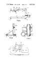
- FIG. 2 is a side elevational view of a motor mount assembly for an electric powered motorcycle constructed in accordance with the present invention
- FIG. 3 is a top plan view of a motor mount assembly for an electric powered motorcycle constructed in accordance with the present invention
- FIG. 4 is a perspective view of a portion of a motor mount assembly constructed in accordance with the present invention, illustrating the manner in which one end of the motor mount assembly is pivotably mounted on an electric powered motorcycle;
- FIG. 5 is a perspective view of a portion of a motor mount assembly constructed in accordance with the present invention, illustrating on an enlarged scale the nature of the construction of the free end of one of the side rails of the motor mount assembly;
- FIG. 6 is a cross sectional view of a motor mount assembly constructed in accordance with the present invention taken substantially along the line 6--6 in FIG. 2, illustrating the reinforcement means employed therein;
- FIG. 7 is a cross sectional view of a motor mount assembly constructed in accordance with the present invention mounted on an electric powered motorcycle taken substantially along the line 7--7 in FIG. 1, illustrating the manner in which the interconnection between one end of the motor mount assembly and the electric powered motorcycle is accomplished;
- FIG. 8 is a schematic diagram of a portion of an electric powered motorcycle embodying a motor mount assembly constructed in accordance with the present invention, illustrating the manner in which the motor mount assembly is capable of pivoting relative to the frame of the electric powered motorcycle.
- the motorcycle 10 includes a frame 12 and a pair of wheels, only one of which, i.e., the rear wheel 14 is illustrated in the drawings.
- the body 16 of the motorcycle 10 is supported on the frame 12 in a conventional manner which is well-known to those skilled in the art.
- the body 16 terminates at one end thereof in a rear fender portion 18 which functions to partially enclose the rear wheel 14.
- the rear fender portion 18 also functions as a support for a tail light and/or directional signal light 20.
- the body 16 also intermediate the ends thereof functions as a support for a seat 22.
- the latter seat 22 obviously may be of differing size and/or configuration from that shown in FIG. 1 if so desired, as long as the seat 22 remains capable of being accommodated on the body 16.
- the electric powered motorcycle 10 derives its power from a multiplicity of rechargeable storage batteries 24.
- the latter as seen with reference to FIG. 1 of the drawings, are supported on a horizontally extending portion 12a of the frame 12.
- the batteries 24 in the eletric powered motorcycle 10 occupy the same position as does the internal-combustion engine in a conventional gasoline powered motorcycle.
- the storage batteries 24 More specifically, as is well-known to those skilled in the art, in a motorcycle which is powered by an internal-combustion engine the latter commonly is supported on the frame at a point located approximately midway between the ends of the motorcycle.
- the frame is suitably configured so as to embody a horizontally extending portion on which the engine is supported.
- the latter location was selected therefor based on a consideration of many factors.
- One important consideration however in this regard involves the weight of the engine and the effect thereof on the stability of the motorcycle. From the standpoint of both the static and the dynamic forces which are known to act on a motorcycle, it has been found to provide the required stability thereto that the engine of a gasoline powered motorcycle is most desirably located in the aforedescribed position.
- an electric powered motorcycle it is the placement of the storage batteries rather than the motor because of the weight and size of the former which becomes important from the stanpoint of ensuring the capability of providing an electric powered motorcycle which has stability.
- the electric powered motorcycle 10 illustrated in FIG. 1 of the drawings embodies a motor mount assembly, generally designated by reference numeral 26, constructed in accordance with the presnet invention.
- the motor mount assembly 26 functions as the means for mounting on the electric powered motorcycle 10 the electric motor 28 thereof.
- the electric motor 28 is connected in electrical circuit relation with the storage batteries 24 through suitable electrical conductor means (not shown) whereby the electric motor 28 receives its power from the storage batteries 24.
- the electric motor 28 in addition is operatively connected to the rear wheel 14 of the electric powered motorcycle 10 whereby to be capable of imparting drive thereto.
- the electric motor 28 has a relatively small sprocket 30 mounted for rotation relative thereto at one end thereof.
- the latter sprocket 30 in turn is connected by means of a chain 32 of suitable length to a relatively large sprocket 34 which is mounted on the rear axle (not shown) of the electric powered motorcycle 10.
- the aforedescribed small sprocket 30, chain 32 and large sprocket 34 constitute a chain drive assembly which is operable to transmit rotation of the small sprocket 30 therefrom through the chain 32 to the large sprocket 34 and therethrough to the rear axle (not shown) to which the large sprocket 34 is rigidly affixed causing the rear wheel 14 to rotate and thereby the electric powered motorcycle 10 to be driven.
- the motor mount assembly 26 in accord with the present invention includes a mount and means for securing the mount on the electric powered motorcycle 10.
- the mount which is generally rectangular in configuration includes a pair of side rails 36 and 38 and a generally planar member 40.
- Each of the side rails 36 and 38 in accord with the illustrated embodiment of the invention consists of an elongated tubular member, which as best understood with reference to FIG. 6 of the drawings, is substantially rectangular in cross section.
- each of the side rails 36 and 38 have substantially identical lengths.
- each of the side rails 36 and 38 Adjacent each end thereof, each of the side rails 36 and 38 is provided with a suitably dimensioned circular opening (not shown) formed completely therethrough.
- a length of pipe 42 is passed through the opening (not shown) provided therefor at one end of each of the side rails 36 and 38.
- the pipe 42 and the side rails 36 and 38 are secured together through the use of any suitable conventional means such as for example by welding, whereby the ends of the pipe 42 extend outwardly a short distance beyond the outer side wall surfaces of the side rails 36 and 38 for a purpose yet to be described.
- the side rails 36 and 38 are secured on the pipe 42 so that the side rails 36 and 38 both extend outwardly in the same direction away from the pipe 42 and have their major axes extending substantially at right angles to the major axis of the pipe 42.
- the length of the pipe 42 is selected so as to have a preestablished dimension whereby when the side rails 36 and 38 each have one end thereof secured thereto the side rails 36 and 38 extend in parallel relation relative to each other and are spaced apart by a predetermined distance.
- the planar member 40 also has one end thereof secured to the pipe 42 at a point intermediate the locations therealong whereat the side rails 36 and 38 are fastened thereto.
- gussets 44 and 46 are preferably employed for purposes of providing additional strength to the motor mount assembly 26, i.e., for purposes of reinforcing the joints formed between the pipe 42 and the side rails 36 and 38.
- the gusset 44 is employed at the joint between the pipe 42 and the side rail 36, and has one side thereof secured to the pipe 42 such as by being welded thereto and the other side thereof secured to the side rail 36 also such as by welding.
- the gusset 46 is located at the joint between the pipe 42 and the side rail 38, and has one side thereof welded to the pipe 42 and the other side thereof welded to the side rail 38.
- the opening (not shown) formed in each of the side rails 36 and 38 adjacent the free end thereof has a bushing 48 and 50, respectively, received therein.
- the bushings 48 and 50 are preferably welded in place within the aforereferenced openings (not shown).
- the length of the bushings 48 and 50 is selected to be such that the bushings 48 and 50 extend outwardly of the side rails 36 and 38, respectively, on either side thereof.
- one of the side rails i.e., side rail 38 has preferably attached thereto a strap-like member 54. More specifically, the latter member 54 has one end thereof secured to the inner side wall surface of the side rail 38 through the use of any suitable conventional form of fastening means commonly employed to rigidly secure metal members together such as for example by means of welding.
- the free end of the member 54 as best understood with reference to FIG. 2 of the drawings, has an opening 56 formed therethrough located in spaced relation to the outer edge thereof.
- the member 54 in accord with the preferred embodiment of the invention, functions as a retainer for the brake drum (not shown) of the electric powered motorcycle 10.
- the opening 56 formed in the member 54 is utilized for purposes of fastening the brake drum (not shown) to the member 54.
- the side rail 38 in addition is provided intermediate its ends with a triangularly-shaped member 58.
- the latter member 58 which more specifically has the appearance of an inverted V, has the ends of the two legs 58a and 58b thereof secured to the side rail 38 through the use of any suitable conventional form of fastening means such as for example by welding.
- the member 58 is provided with an outwardly projecting lug 60 which has an internally threaded opening (not shown) formed therethrough.
- An adjustment screw 62 is threadedly engaged in the lug 60.
- the screw 62 is interconnected to the brake cable (not shown) of the electric powered motorcycle 10 whereby through employment of the screw 62 adjustments may be made to the brake cable (not shown).
- the member 40 is rigidly affixed to the pipe 42 at a point intermediate the locations whereat the side rails 36 and 38 are joined to the pipe 42.
- one end of the member 40 terminates in an arcuate-shaped recess (not shown) suitably dimensioned so as to conform to the circumference of the pipe 42 whereby the latter is capable of being received in the former.
- the member 40 is secured to the pipe 42 by means of welding.
- the member 40 as best understood with reference to FIGS. 1, 2, 3 and 6 of the drawings consists of a planar portion 64 having an outwardly extending flange portion 66 provided on one side thereof.
- the planar portion 64 and the flange portion 66 are formed as two separate parts which are joined together such as by welding to produce the integral member 40.
- the planar portion 64 bears a resemblance generally to the letter Y, the latter configuration being produced by the two legs 64a and 64b of the planar portion 64 which diverge outwardly from the trunk portion 64c thereof. Adjacent the free ends thereof, each of the legs 64a and 64b of the planar portion 64 has formed therein an elongated slot 68 and 70 respectively.
- the function of the slots 68 and 70 which are each slightly arcuate in configuration, will be described more fully hereinafter in connection with a discussion of the manner in which the electric motor 28 is secured to the planar member 40.
- the planar portion 64 also has an opening 72 formed therein at a point spaced somewhat from the center of the planar portion 64, the function of which also will be described subsequently.
- the flange portion 66 is generally L-shaped in configuration. More specifically, the flange portion 66 includes a short leg 66a which is joined integrally with a longer leg 66b so that the major axes thereof extend substantially at right angles to each other. As depicted in the drawings, the short leg 66a of the flange portion 66 extends the length of and is fastened to the leg 64a of the planar portion 64 while the longer leg 66b of the flange portion 66 extends the length of and is fastened to the trunk portion 66c of the planar portion 64.
- the length of the leg 66b of the flange portion 66 is made sufficiently long so that the free end thereof is capable of being secured to the pipe 42 such as by being welded thereto.
- the planar member 40 is further reinforced through the use of a brace 74 which has one end thereof welded to the pipe 42 and the other end thereof welded to the side of the planar portion 64 opposite to that on which the flange portion 66 is located.
- the electric motor 28 is mounted on the planar member 40 with the sprocket 30 with which the electric motor 28 is provided being located in juxtaposed relation to the planar portion 64.
- three points of attachment are preferably employed between the electric motor 28 and the planar portion 64. More specifically, a first threaded fastener 76 is passed through the opening 72 in the planar portion 64 and into threaded engagement with the electric motor 28. In addition, a pair of threaded fasteners 78 and 80 are also passed through the slots 68 and 70, respectively, and into engagement with the electric motor 28.
- the above described mode of mounting the electric motor 28 on the planar member 40 is preferably employed inasmuch as it permits a rigid mounting to be had of the electric motor 28 on the planar portion 64 while at the same time enabling the position of the electric motor 28 relative to the planar portion 64 to be varied for purposes of making adjustments in the tension of the chain 32 which spans the sprockets 30 and 34.
- the latter adjustment is accomplished by loosening the fasteners 78 and 80 and if necessary the threaded fastener 76 to a sufficient extent to enable the electric motor 28 to pivot relative to the planar portion 64 about the fastener 76.
- the motor mount assembly 26 of the present invention has one end thereof pivotably mounted on the frame 12 of the electric powered motorcycle 10 and the other end thereof operatively connected to the rear axle (not shown) of the motorcycle 10.
- the latter in accord with the illustrated embodiment thereof includes a pair of upwardly and rearwardly extending frame members 82 and 84.
- the latter frame members 82 and 84 are spaced apart by a distance corresponding to the length of the pipe 42 whereby the motor mount assembly 26 is capable of being interposed therebetween.
- each of the frame members 82 and 84 is provided intermediate its ends with a triangularly-shaped projection 86, only one of which is visible in the drawings.
- the projections 86 are preferably affixed to the frame members 82 and 84 by being welded thereto.
- the projections 86 are each provided at a point spaced inwardly from the apex thereof with a suitably dimensioned opening (not shown).
- a solid rod 88 is positioned within the pipe 42 whereby to extend the length thereof.
- the rod 88 is suitably dimensioned so as to be capable of being inserted through the openings (not shown) provided for this purpose in each of the projections 86.
- each end of the rod 88 is preferably provided with threads for at least a portion of the length thereof.
- a suitable nut 90 and if desired a suitable washer (not shown) is received on each end of the rod 88 outwardly of the projections 86 and in threaded engagement with the threads formed on the ends of the rod 88 whereby the rod 88 and therefore one end of the motor mount assembly 26 is secured to the projections 86 between the frame members 82 and 84.
- the latter as referred to previously is attached to the rear axle (not shown) of the electric powered motorcycle 10. More specifically, the rear axle (not shown) of the motorcycle 10 extends through the bushings 48 and 50 which, as described previously hereinabove, are supported on the side rails 36 and 38, respectively, in fixed relation thereto.
- the rear axle (not shown) may have threads formed thereon at each end thereof for at least a portion of the length thereof.
- a suitably dimensioned nut 92 may be positioned on the rear axle (not shown) outwardly of the side rails 36 and 38 and in threaded engagement therewith.
- FIG. 1 of the drawings there also exists another interconnection between the side rails 36 and 38 of the motor mount assembly 26 and the frame 12 of the electric powered motorcycle 10.
- the electric powered motorcycle 10 is provided with a pair of shock absorbers 94 of conventional design, only one of which is visible in the drawings, which are connected at one end to the motor assembly 26 and at the other end to the frame 12 of the motorcycle 10. More specifically, the pair of shock absorbers 94 each have one end thereof fastened to a corresponding one of the side rails 36 and 38.
- some form of conventional threaded fastener 96 is passed through the opening 52 formed in the corresponding one of the side rails 36 and 38, and also through a similar opening (not shown) provided for this purpose at one end of each of the shock absorbers 94.
- the other end of each of the pair of shock absorbers 94 is connected to the frame 12.
- the shock absorbers 94 at the other end thereof are each provided with another suitably configured opening (not shown) capable of receiving therein a threaded fastener 98.
- the latter fastener 98 is also passed through a suitably dimensioned opening (not shown) provided for this purpose in a projection 100, only one of which is visible in the drawings, with which each of the frame members 82 and 84 of the frame 12 is provided.
- Some form of locking means such as a conventional internally threaded nut may be threadedly engaged on one threaded end of the fasteners 96 and 98 after the latter in the manner described above have been passed through the side rails 36, 38 and one end of the shock absorbers 94, and the other end of the shock absorbers 94 and the projections 100, respectively, whereby to effect a secure connection therebetween.
- the electric motor 28 is not only capable of being connected in electrical circuit relation with the storage batteries 24 so as to derive its power therefrom and of being operatively connected to the rear axle of the motorcycle 10 so as to impart drive thereto, but also the electric motor 28 is mounted so as to be movable relative to the frame 12. More specifically, the motor mount assembly 26 when so embodied in the electric powered motorcycle 10 enables the electric motor 28 to move whenever the rear wheel 14 moves relative to the frame 12 of the motorcycle 10 upon hitting a bump, etc.
- the flange portion 66 supported on one side of the planar portion 64 which has one end thereof rigidly affixed to the pipe 42 whereby to provide added rigidity to the upstanding planar portion 64 and also functions in the nature of a chain guard for the chain 32 as the latter passes around the sprocket 30 could obviously take some other form without departing from the essence of the invention.
- the shock absorbers 94 which have one end thereof connected to the side rails 36 and 38 at a point spaced inwardly of the bushings 48 and 50, respectively, in which the rear axle is supported could be mounted in some other manner.
- the aforereferenced connection between one end of the shock absorbers 94 and the side rails 36 and 38 could be effected by operatively connecting the aforesaid one end of the shock absorbers 94 to the rear axle after the latter has been inserted through the bushings 48 and 50.
- the side rails 36 and 38 in accord with the illustrated embodiment of the invention comprise tubular members having a rectangular cross section, the side rails 36 and 38 could obviously embody some other form of configuration as long as the side rails 36 and 38 continue to possess the necessary structural strength required thereby, without departing from the essence of the invention.
- the present invention provides a novel and improved motor mount assembly which is particularly suited for employment in an electric powered motorcycle.
- a motor mount assembly is provided which is operable for mounting an electric motor in an electric powered motorcycle so that the electric motor is capable of deriving its power from a multiplicity of storage batteries.
- the motor mount assembly of the present invention is operable for mounting an electric motor in an electric powered motorcycle so that the electric motor is drivingly connected to the rear wheel of the motorcycle.
- a motor mount assembly is provided which is operable for mounting an electric motor in an electric powered motorcycle so that the electric motor is movable relative to the frame of the motorcycle.
- a motor mount assembly for an electric powered motorcycle which is operable for mounting the electric motor thereof so that whenever the rear wheel moves relative to the frame by virtue of hitting a bump, etc. the electric motor is also caused to move whereby the electric motor wwill continually bear the same relationship with respect to the axle on which the rear wheel is mounted.
- a motor mount assembly for an electric powered motorcycle has been provided which is relatively inexpensive to manufacture, easy to assemble on the motorcycle, and is capable of effectively resisting the adverse environmental conditions to which the operating components of a motorcycle are commonly exposed.
Landscapes
- Engineering & Computer Science (AREA)
- Mechanical Engineering (AREA)
- Chemical & Material Sciences (AREA)
- Combustion & Propulsion (AREA)
- Transportation (AREA)
- Automatic Cycles, And Cycles In General (AREA)
Abstract
Description
Claims (5)
Priority Applications (1)
| Application Number | Priority Date | Filing Date | Title |
|---|---|---|---|
| US05/512,418 US3937291A (en) | 1974-10-07 | 1974-10-07 | Motor mount for electric powered motorcycle |
Applications Claiming Priority (1)
| Application Number | Priority Date | Filing Date | Title |
|---|---|---|---|
| US05/512,418 US3937291A (en) | 1974-10-07 | 1974-10-07 | Motor mount for electric powered motorcycle |
Publications (1)
| Publication Number | Publication Date |
|---|---|
| US3937291A true US3937291A (en) | 1976-02-10 |
Family
ID=24038994
Family Applications (1)
| Application Number | Title | Priority Date | Filing Date |
|---|---|---|---|
| US05/512,418 Expired - Lifetime US3937291A (en) | 1974-10-07 | 1974-10-07 | Motor mount for electric powered motorcycle |
Country Status (1)
| Country | Link |
|---|---|
| US (1) | US3937291A (en) |
Cited By (14)
| Publication number | Priority date | Publication date | Assignee | Title |
|---|---|---|---|---|
| EP0050057A3 (en) * | 1980-10-15 | 1982-05-12 | Cycles Peugeot Societe Dite: | Electrically propelled two-wheeled vehicle |
| EP0469995A1 (en) * | 1990-08-02 | 1992-02-05 | Honda Giken Kogyo Kabushiki Kaisha | Electrically operated vehicle |
| US5222572A (en) * | 1989-07-13 | 1993-06-29 | Honda Giken Kogyo Kabushiki Kaisha | Electric motor driven vehicle and power unit thereof |
| US5383530A (en) * | 1991-10-21 | 1995-01-24 | Yamaha Hatsudoki Kabushiki Kaisha | Motorcycle |
| DE4344008A1 (en) * | 1993-12-23 | 1995-06-29 | Itg Engineering Gmbh Zschopau | Hybrid drive bike |
| US5524726A (en) * | 1995-04-18 | 1996-06-11 | Tenergy L.L.C. | Swing arm supported electrical drive assembly for powering cycles |
| GB2330119A (en) * | 1997-10-10 | 1999-04-14 | Mohammad Davar Kheradvar | Drive mechanism for a cycle |
| US6575260B2 (en) * | 2001-02-06 | 2003-06-10 | Joseph Roger Bourget | Motorcycle having jack shaft to accommodate wide rear tire |
| US20050023061A1 (en) * | 2003-07-29 | 2005-02-03 | Eric Noble | Motorized cycle |
| US20080251308A1 (en) * | 2005-08-24 | 2008-10-16 | Dezso Molnar | Ground Air Water Craft |
| US20110183577A1 (en) * | 2010-01-22 | 2011-07-28 | Anderson Model Co., Ltd. | Remote control two-wheel model |
| US20150203159A1 (en) * | 2012-09-12 | 2015-07-23 | Shiro Tamura | Suspension structure for in-wheel motor drive device |
| US9428040B2 (en) * | 2012-12-21 | 2016-08-30 | Honda Motor Co., Ltd. | Electric motor mounting structure |
| EP4063249A1 (en) * | 2021-03-23 | 2022-09-28 | TVS Motor Company Limited | A motor vehicle with at least two wheels |
Citations (6)
| Publication number | Priority date | Publication date | Assignee | Title |
|---|---|---|---|---|
| US2275050A (en) * | 1940-11-12 | 1942-03-03 | Salsbury Corp | Subframe for motor vehicles |
| US2604179A (en) * | 1950-03-31 | 1952-07-22 | Gilardi Carlo | Frame for light motorcycles or motor-bicycles |
| FR1083259A (en) * | 1953-09-11 | 1955-01-06 | Engine suspension for motor cycles | |
| US3631936A (en) * | 1970-01-05 | 1972-01-04 | Frederick G Schweser | Floating wheel and power assembly motorcycles |
| US3773131A (en) * | 1970-03-31 | 1973-11-20 | Motobecane Ateliers | Electric autocycle |
| US3817342A (en) * | 1973-05-14 | 1974-06-18 | Rokon Inc | Motorcycle brakes |
-
1974
- 1974-10-07 US US05/512,418 patent/US3937291A/en not_active Expired - Lifetime
Patent Citations (6)
| Publication number | Priority date | Publication date | Assignee | Title |
|---|---|---|---|---|
| US2275050A (en) * | 1940-11-12 | 1942-03-03 | Salsbury Corp | Subframe for motor vehicles |
| US2604179A (en) * | 1950-03-31 | 1952-07-22 | Gilardi Carlo | Frame for light motorcycles or motor-bicycles |
| FR1083259A (en) * | 1953-09-11 | 1955-01-06 | Engine suspension for motor cycles | |
| US3631936A (en) * | 1970-01-05 | 1972-01-04 | Frederick G Schweser | Floating wheel and power assembly motorcycles |
| US3773131A (en) * | 1970-03-31 | 1973-11-20 | Motobecane Ateliers | Electric autocycle |
| US3817342A (en) * | 1973-05-14 | 1974-06-18 | Rokon Inc | Motorcycle brakes |
Cited By (21)
| Publication number | Priority date | Publication date | Assignee | Title |
|---|---|---|---|---|
| EP0050057A3 (en) * | 1980-10-15 | 1982-05-12 | Cycles Peugeot Societe Dite: | Electrically propelled two-wheeled vehicle |
| FR2497734A1 (en) * | 1980-10-15 | 1982-07-16 | Peugeot Cycles | TWO WHEEL VEHICLE WITH ELECTRIC PROPULSION |
| US5222572A (en) * | 1989-07-13 | 1993-06-29 | Honda Giken Kogyo Kabushiki Kaisha | Electric motor driven vehicle and power unit thereof |
| EP0469995A1 (en) * | 1990-08-02 | 1992-02-05 | Honda Giken Kogyo Kabushiki Kaisha | Electrically operated vehicle |
| US5501292A (en) * | 1990-08-02 | 1996-03-26 | Honda Giken Kogyo Kabushiki Kaisha | Electrically operated vehicle |
| US5657830A (en) * | 1990-08-02 | 1997-08-19 | Honda Giken Kogyo Kabushini Kaisha | Electrically operated saddle type vehicle |
| US5383530A (en) * | 1991-10-21 | 1995-01-24 | Yamaha Hatsudoki Kabushiki Kaisha | Motorcycle |
| DE4344008A1 (en) * | 1993-12-23 | 1995-06-29 | Itg Engineering Gmbh Zschopau | Hybrid drive bike |
| US5524726A (en) * | 1995-04-18 | 1996-06-11 | Tenergy L.L.C. | Swing arm supported electrical drive assembly for powering cycles |
| GB2330119B (en) * | 1997-10-10 | 2002-04-17 | Mohammad Davar Kheradvar | Drive mechanism for a cycle |
| GB2330119A (en) * | 1997-10-10 | 1999-04-14 | Mohammad Davar Kheradvar | Drive mechanism for a cycle |
| US6575260B2 (en) * | 2001-02-06 | 2003-06-10 | Joseph Roger Bourget | Motorcycle having jack shaft to accommodate wide rear tire |
| US20050023061A1 (en) * | 2003-07-29 | 2005-02-03 | Eric Noble | Motorized cycle |
| US6880662B2 (en) * | 2003-07-29 | 2005-04-19 | Eric Noble | Motorized cycle |
| US20080251308A1 (en) * | 2005-08-24 | 2008-10-16 | Dezso Molnar | Ground Air Water Craft |
| US7815144B2 (en) * | 2005-08-24 | 2010-10-19 | Dezso Molnar | Ground air water craft |
| US20110183577A1 (en) * | 2010-01-22 | 2011-07-28 | Anderson Model Co., Ltd. | Remote control two-wheel model |
| US20150203159A1 (en) * | 2012-09-12 | 2015-07-23 | Shiro Tamura | Suspension structure for in-wheel motor drive device |
| US9771105B2 (en) * | 2012-09-12 | 2017-09-26 | Ntn Corporation | Suspension structure for in-wheel motor drive device |
| US9428040B2 (en) * | 2012-12-21 | 2016-08-30 | Honda Motor Co., Ltd. | Electric motor mounting structure |
| EP4063249A1 (en) * | 2021-03-23 | 2022-09-28 | TVS Motor Company Limited | A motor vehicle with at least two wheels |
Similar Documents
| Publication | Publication Date | Title |
|---|---|---|
| US3937291A (en) | Motor mount for electric powered motorcycle | |
| US20040035626A1 (en) | Vehicle and adjustable steering shaft therefor | |
| US20040129483A1 (en) | Vehicle and adjustable steering shaft therefor | |
| KR19980064007A (en) | Fender and back rest mounting structure and mounting method of motorcycle | |
| US2792899A (en) | Motor bicycles or scooters | |
| US5107952A (en) | Saddle type off-road vehicle | |
| CA2480831C (en) | Rear fender and related support structure for a motorcycle, and motorcycle including same | |
| JPH03193581A (en) | Motorcycle | |
| US3375024A (en) | Bicycle frame | |
| US4081117A (en) | Saddle bag bracket | |
| JPS63500232A (en) | Bicycles and fixed seats | |
| JP3485996B2 (en) | Swing arm structure for swing unit type vehicle | |
| US7740100B2 (en) | Cover structure for buggy vehicle | |
| US5342074A (en) | Dual recumbent vehicle | |
| US3507346A (en) | Compact snow vehicle | |
| EP0581318B1 (en) | Frame structure for motorcycle | |
| US2589793A (en) | Demountable propelling unit for vehicles | |
| JP3623844B2 (en) | Muffler mounting structure | |
| JP3376790B2 (en) | Motorcycle tail lamp mounting structure | |
| JPS5843879A (en) | floor skirt structure | |
| US4099738A (en) | Bicycle accessory means | |
| US2670965A (en) | Three-wheeled vehicle in which the driver and a passenger sit astraddle | |
| JPH0132633Y2 (en) | ||
| JP3073385B2 (en) | Structure of generator mounting bracket | |
| JPH0438280A (en) | Prop stand mounting device for starter |
Legal Events
| Date | Code | Title | Description |
|---|---|---|---|
| AS | Assignment |
Owner name: WELLS FARGO BANK, CALIFORNIA Free format text: SECURITY AGREEMENT;ASSIGNOR:CORBIN PACIFIC, INC.;REEL/FRAME:010340/0575 Effective date: 19980702 |
|
| AS | Assignment |
Owner name: CORBIN PACIFIC, INC., CALIFORNIA Free format text: RELEASE BY SECURED PARTY;ASSIGNOR:WELLS FARGO BANK, NATIONAL ASSOCIATION;REEL/FRAME:022575/0602 Effective date: 20090224 |
|
| AS | Assignment |
Owner name: COMERICA BANK, CALIFORNIA Free format text: SECURITY AGREEMENT;ASSIGNOR:CORBIN PACIFIC, INC.;REEL/FRAME:022584/0133 Effective date: 20090315 |
|
| AS | Assignment |
Owner name: CORBIN PACIFIC, INC., CALIFORNIA Free format text: RELEASE BY SECURED PARTY;ASSIGNOR:COMERICA BANK;REEL/FRAME:029395/0734 Effective date: 20121128 |