US3920176A - Solder method - Google Patents
Solder method Download PDFInfo
- Publication number
- US3920176A US3920176A US504430A US50443074A US3920176A US 3920176 A US3920176 A US 3920176A US 504430 A US504430 A US 504430A US 50443074 A US50443074 A US 50443074A US 3920176 A US3920176 A US 3920176A
- Authority
- US
- United States
- Prior art keywords
- solder
- tubular element
- female
- soldering
- space
- Prior art date
- Legal status (The legal status is an assumption and is not a legal conclusion. Google has not performed a legal analysis and makes no representation as to the accuracy of the status listed.)
- Expired - Lifetime
Links
- 229910000679 solder Inorganic materials 0.000 title claims abstract description 123
- 238000000034 method Methods 0.000 title claims abstract description 52
- 238000005476 soldering Methods 0.000 claims abstract description 41
- 239000011248 coating agent Substances 0.000 claims abstract description 17
- 238000000576 coating method Methods 0.000 claims abstract description 17
- 229910052751 metal Inorganic materials 0.000 claims abstract description 14
- 239000002184 metal Substances 0.000 claims abstract description 14
- 238000001816 cooling Methods 0.000 claims description 7
- 230000000694 effects Effects 0.000 claims description 6
- 238000007654 immersion Methods 0.000 claims description 3
- 238000000926 separation method Methods 0.000 claims description 2
- 238000007711 solidification Methods 0.000 claims description 2
- 230000008023 solidification Effects 0.000 claims description 2
- 230000015572 biosynthetic process Effects 0.000 abstract description 7
- 238000007598 dipping method Methods 0.000 description 6
- 238000005755 formation reaction Methods 0.000 description 6
- 229910052782 aluminium Inorganic materials 0.000 description 5
- XAGFODPZIPBFFR-UHFFFAOYSA-N aluminium Chemical compound [Al] XAGFODPZIPBFFR-UHFFFAOYSA-N 0.000 description 5
- 238000010438 heat treatment Methods 0.000 description 4
- 239000000463 material Substances 0.000 description 4
- 239000012530 fluid Substances 0.000 description 3
- 230000004907 flux Effects 0.000 description 3
- 230000009471 action Effects 0.000 description 2
- 238000007796 conventional method Methods 0.000 description 2
- 230000008030 elimination Effects 0.000 description 2
- 238000003379 elimination reaction Methods 0.000 description 2
- 238000003780 insertion Methods 0.000 description 2
- 230000037431 insertion Effects 0.000 description 2
- 239000007788 liquid Substances 0.000 description 2
- 238000004519 manufacturing process Methods 0.000 description 2
- 230000008569 process Effects 0.000 description 2
- 238000005406 washing Methods 0.000 description 2
- NLXLAEXVIDQMFP-UHFFFAOYSA-N Ammonium chloride Substances [NH4+].[Cl-] NLXLAEXVIDQMFP-UHFFFAOYSA-N 0.000 description 1
- VHUUQVKOLVNVRT-UHFFFAOYSA-N Ammonium hydroxide Chemical compound [NH4+].[OH-] VHUUQVKOLVNVRT-UHFFFAOYSA-N 0.000 description 1
- CYTYCFOTNPOANT-UHFFFAOYSA-N Perchloroethylene Chemical group ClC(Cl)=C(Cl)Cl CYTYCFOTNPOANT-UHFFFAOYSA-N 0.000 description 1
- WYTGDNHDOZPMIW-RCBQFDQVSA-N alstonine Natural products C1=CC2=C3C=CC=CC3=NC2=C2N1C[C@H]1[C@H](C)OC=C(C(=O)OC)[C@H]1C2 WYTGDNHDOZPMIW-RCBQFDQVSA-N 0.000 description 1
- 235000011114 ammonium hydroxide Nutrition 0.000 description 1
- 230000005540 biological transmission Effects 0.000 description 1
- 239000000919 ceramic Substances 0.000 description 1
- 229910052729 chemical element Inorganic materials 0.000 description 1
- 239000003795 chemical substances by application Substances 0.000 description 1
- 238000004140 cleaning Methods 0.000 description 1
- 238000005260 corrosion Methods 0.000 description 1
- 230000007797 corrosion Effects 0.000 description 1
- 238000009826 distribution Methods 0.000 description 1
- 239000002320 enamel (paints) Substances 0.000 description 1
- 239000011521 glass Substances 0.000 description 1
- 230000006698 induction Effects 0.000 description 1
- 230000005855 radiation Effects 0.000 description 1
- 230000009467 reduction Effects 0.000 description 1
- 238000005057 refrigeration Methods 0.000 description 1
- 238000003303 reheating Methods 0.000 description 1
- 238000010079 rubber tapping Methods 0.000 description 1
- 239000000126 substance Substances 0.000 description 1
- 229950011008 tetrachloroethylene Drugs 0.000 description 1
- XLYOFNOQVPJJNP-UHFFFAOYSA-N water Substances O XLYOFNOQVPJJNP-UHFFFAOYSA-N 0.000 description 1
- 239000002023 wood Substances 0.000 description 1
Images


Classifications
-
- B—PERFORMING OPERATIONS; TRANSPORTING
- B23—MACHINE TOOLS; METAL-WORKING NOT OTHERWISE PROVIDED FOR
- B23K—SOLDERING OR UNSOLDERING; WELDING; CLADDING OR PLATING BY SOLDERING OR WELDING; CUTTING BY APPLYING HEAT LOCALLY, e.g. FLAME CUTTING; WORKING BY LASER BEAM
- B23K3/00—Tools, devices, or special appurtenances for soldering, e.g. brazing, or unsoldering, not specially adapted for particular methods
- B23K3/06—Solder feeding devices; Solder melting pans
- B23K3/0646—Solder baths
- B23K3/0669—Solder baths with dipping means
-
- B—PERFORMING OPERATIONS; TRANSPORTING
- B23—MACHINE TOOLS; METAL-WORKING NOT OTHERWISE PROVIDED FOR
- B23K—SOLDERING OR UNSOLDERING; WELDING; CLADDING OR PLATING BY SOLDERING OR WELDING; CUTTING BY APPLYING HEAT LOCALLY, e.g. FLAME CUTTING; WORKING BY LASER BEAM
- B23K1/00—Soldering, e.g. brazing, or unsoldering
- B23K1/0008—Soldering, e.g. brazing, or unsoldering specially adapted for particular articles or work
- B23K1/0012—Brazing heat exchangers
-
- F—MECHANICAL ENGINEERING; LIGHTING; HEATING; WEAPONS; BLASTING
- F28—HEAT EXCHANGE IN GENERAL
- F28F—DETAILS OF HEAT-EXCHANGE AND HEAT-TRANSFER APPARATUS, OF GENERAL APPLICATION
- F28F9/00—Casings; Header boxes; Auxiliary supports for elements; Auxiliary members within casings
- F28F9/26—Arrangements for connecting different sections of heat-exchange elements, e.g. of radiators
- F28F9/262—Arrangements for connecting different sections of heat-exchange elements, e.g. of radiators for radiators
- F28F9/268—Arrangements for connecting different sections of heat-exchange elements, e.g. of radiators for radiators by permanent joints, e.g. by welding
-
- B—PERFORMING OPERATIONS; TRANSPORTING
- B23—MACHINE TOOLS; METAL-WORKING NOT OTHERWISE PROVIDED FOR
- B23K—SOLDERING OR UNSOLDERING; WELDING; CLADDING OR PLATING BY SOLDERING OR WELDING; CUTTING BY APPLYING HEAT LOCALLY, e.g. FLAME CUTTING; WORKING BY LASER BEAM
- B23K2101/00—Articles made by soldering, welding or cutting
- B23K2101/04—Tubular or hollow articles
- B23K2101/14—Heat exchangers
Definitions
- ABSTRACT A method of soldering a metal tubular element having an arcuate portion and an end portion to a metal female element receiving the end portion and defining a distal annular solder space.
- the elements are mechanically secured together and immersed in a solder bath with the solder space opening downwardly and with the arcuate portion of the tubular element lowermost.
- the elements may be preheated for improved solder coating thereof in the bath.
- solder coated elements are withdrawn from the bath and immediately inverted to allow the melted solder thereon to run toward the end portion and into the solder space to prevent formation of icicles on the arcuate portion and provide animproved soldered connection to the female element.
- solder does not always completely fill the solder space or shrinkage voids or shrinkage cracks associated with cooling of molten solder form so that water and other undesirable material may collect therein and potentially cause failure of the sealed connection as by a freeze-thaw action or corrosion.
- the present invention comprehends an improved method of dip.soldering tubular elements eliminating the formation of icicles and the like and concurrently providing an improved soldered connection. More specifically, the invention comprehends providing a dip soldered connection between a metal tubular element having an arcuate portion and leg portions and a pair of female elements.
- the soldering method is applied to the forming of a fin and tube heat exchanger with the tubular element comprising a return bend and the female elements defining hairpin socket portions thereof.
- the return bends are firstly mechanically secured to the hairpin portions by wedging the distal ends of the return bend legs into the distal ends of the hairpin elements.
- the hairpin ends are flared to define an annular solder space coaxially about the return bend legs.
- the distal end of the return bend legs may be provided with lugs for facilitating the mechanical connection and the hairpin end portions may define annular gripping portions into which the distal ends of the return bends are snugly fitted.
- the distal ends of the hairpin portions may further define annular stop portions for limiting the insertion of the return bend legs thereinto.
- the invention comprehends an improved method of forming improved heatexchangers eliminating disadvantages of prior art methods while providing an improved positive solder joint.
- FIG. 2 is a fragmentary side elevation of a 'heatexchanger having solder joints provided by the improved method of the present invention
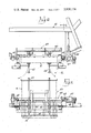
- FIG. 4 is a fragmentary top plan view of one'heat exchanger holding station of the apparatus
- FIG. 5 is a front elevation of the portion of the apparatus illustrated in FIG. 4;
- FIG. 6 is a fragmentary vertical section taken substantially along the lines 6-6 of FIG. 4 and illustrating the immersing of the return bends in the solderbath;
- FIG. 7 is a section similar to that of FIG. 6 but with the heat exchanger disposed in the inverted position subsequent to the solder dipping operation;
- FIG. 8 is a fragmentary enlarged diametric section of the soldered tubular elements.
- the presentinvention is concerned with providing an improved solder joint 17 while concun I rently eliminating the formation of tears or icicles on the arcuate return bend portions 27.
- the invention comprehends the mechanical connection of the aluminum return bends to the aluminum hairpin legs 18 and 19 by the wedging of the return bend legs 28-and 29 into the distal end portions 20 permitting the heatexchanger 10 to be dis- I posed with the assembled return bend and hairpin ele ments lowermost as shown in FIG. 6.
- the assembled may be cleaned and .degreased by conventional methods; such as with perchlorethylene and suitable cleaning chemicals.
- the socket portions. 21 of the hairpin elements are immersed with the return bends into the sol. der bath.
- One such solder bath is illustrated in James J.
- a heat exchanger generally designated 10 is shown to comprise a tube and fin heat exchanger having a serpentine tube structure 11 defined by plural hairpins 12 havingend portions 13 extending through a header plate 14 and defining female socket elements for connection of .retum bends 15.
- a plurality of fins 16 extend transversely to the hairpin elements 12 for providing improved heat transfer betweenthe lar end portions 21 terminating in distal flared ends22 and defining anannular solder space "23.
- the-hairpin end portions 20 are provided with inner radially reduced end portions'24 having a diameter lessthan that of portions 21.
- Portions 24 are joined to the tubular legs 18 by inwardly tapered portions 25 defining an inner, annular tube stop shoulder 26.
- hairpins may be mounted to the conveyor at a loading 1 station generally designated-35 and sequentially delivered to preheatstations 36, 37 and 38 prior to the delivery to the solder pot as shown.
- the conveyor may comprise a table rotatable about an axis 39 by suitable drive means (not shown).
- the heat exchanger 10 may be removably secured to the conveyor 40 by suitable clamp portions41 and 42 of a carrier 43 which clamp the heat exchanger against a backup structure 44.
- the carrier 43 is rotatably about a horizontalaxis on a shaft'45 which is driven from a drive shaft 46 I through a suitable bevel gear transmission 47.
- the horizontal axis of rotation 48 of shaft 45 is disposed closer to the return bend portion of heat exchanger 10 than the opposite edge portion 49, as shown in FIGS. 6 and 7, tominimize swinging of, the return bend portiontin the inversion of the heatexchanger.
- the heat exchanger is raised from the tank 34 and concurrently rotated about axis48 so as to dispose the return bends 27 uppermost, as illustrated in FIG. 7.
- the solder coating on the return bends is substantially tion of icicles or tears, and synergistically eliminate voids in the filling of the solder space and causing for-
- a body of solder 32 is provided mation of a solder fillet 50 at the outer end of the solder space 23.
- the provision of fillet 50 effectively avoids the collection of fluids and other material between the elements 12 and 27 so as to assure long trouble-free life of the structure.
- the inversion of the heat exchanger should be smoothly or evenly performed so that molten solder is not displaced from the joint during the inversion step.
- the structure Upon inversion of the heat exchanger, as illustrated in FIG. 7, the structure is moved laterally from above the ultrasonic solder pot 24 sequentially to cooling stations 51 and 52 for setting of the solder to form the solder joint, as illustrated in FIG. 8.
- the soldered heat exchanger may then be unloaded from the conveyor at a subsequent unloading station 53, completing the soldering operation.
- the conveyor may be suitably controlled to provide suitable dwell periods for the heat exchangers at each of the different zones and stations.
- the effecting of the inversion of the coated joint immediately upon removal from the solder bath assures the desired eliminations of icicles and tears on the return bends while concurrently assuring the elimination of voids in the solder space 23 and the formation of the desired fillets 50.
- the use of ultrasonic vibration in the dipping operation provides further improved coating of the elements in effecting the solder joint.
- the method of soldering a metal tubular element having an outer portion and an inner end portion to a metal female element receiving said end portion and defining a distal annular solder space in said female element about said end portion comprising the steps of: coaxially securing said end portion into said female element with said outer portion disposed outwardly thereof; immersing the secured end portion in a molten solder bath with said space opening downwardly to apply a coating of molten solder to said tubular element and into said solder space; withdrawing the molten solder coated tubular element from the bath and, prior to solidifying of said solder on said tubular element inverting the same to dispose said space to open upwardly and allow molten solder on said tubular element to run into and fill voids in said solder space and to form a fillet at the upper end of said solder space; and setting the solder.
- each said female element defines a tube stop and said leg portions of the tubular element are inserted into the female element to adjacent said tube stops for facilitated assembly thereof.
- each said female element comprises a tubular element having an expanded distal end defining said solder space.
Abstract
A method of soldering a metal tubular element having an arcuate portion and an end portion to a metal female element receiving the end portion and defining a distal annular solder space. The elements are mechanically secured together and immersed in a solder bath with the solder space opening downwardly and with the arcuate portion of the tubular element lowermost. The elements may be preheated for improved solder coating thereof in the bath. The solder coated elements are withdrawn from the bath and immediately inverted to allow the melted solder thereon to run toward the end portion and into the solder space to prevent formation of icicles on the arcuate portion and provide an improved soldered connection to the female element.
Description
United States Patent Becker et a1. Nov. 18, 1975 1 SOLDER METHOD [75 Inventors: John E. Becker; Adolph E. Schultz, Examlner 1ames Jones both of Evansville, Ind.
Assistant ExaminerK. J. Ramsey Attorney, Agent, 0r'Firm-Wegner, Stellman, McCord, Wiles & Wood [57 ABSTRACT A method of soldering a metal tubular element having an arcuate portion and an end portion to a metal female element receiving the end portion and defining a distal annular solder space. The elements are mechanically secured together and immersed in a solder bath with the solder space opening downwardly and with the arcuate portion of the tubular element lowermost. The elements may be preheated for improved solder coating thereof in the bath. The solder coated elements are withdrawn from the bath and immediately inverted to allow the melted solder thereon to run toward the end portion and into the solder space to prevent formation of icicles on the arcuate portion and provide animproved soldered connection to the female element.
16 Claims, 8 Drawing Figures [73] Assignee: Whirlpool Corporation, Benton Harbor, Mich.
[22] Filed: Sept. 9, 1974 [21] Appl. No.: 504,430
[52] US. Cl. 228/183; 228/257; 228/262 [51] Int. Cl. B23K l/08; B23K 1/06 [58] Field of Search. 29/157.3 R, 157.3 B, 157.3 C, 29/157.6, 471.1, 503; 118/56; 117/114 R [5 6] References Cited UNITED STATES PATENTS 2,417,472 3/1947 Dorff 118/56 UX 2,417,662 3/1947 29/503 X 2,925,063: 2/1960 118/500 3,341,353 9/1967 Johnson 117/94 3,750,248 8/1973 Morris 29/157.3 R 3,752,381 8/1973 Watson, Jr 228/36 X 3,760,481 9/1973 Greever 29/157.3 R 3,833,986 9/1974 DeCicco 29/157.3 A
US. Patent Nov. 18, 1975 PRE'-H EAT STATION PRE- HEAT 37 STATION PRE-HEAT STATION Sheet 1 of 3 POT LoA'b IN 6 STATION /5 :3 COOL N6 1 O R 53 UN LOADING h STATION 52 COOLING STATION 3 40 COOLING STATION L ::l u LT RASONIC SOLDER Sheet 2 of 3 3,920,176
U.S. Patent Nov. 18, 1975 U.S. Patant Nov. 18,1975 Sheet3of3 3,920,176
2. Description of the Prior Art In one conventional form of heat exchanger, such as used in an air conditioner or other refrigeration apparatus, a tube and fin structure is provided having a serpentine fluid conducting tube and transversely extending fins. The serpentine tube is formed by sealingly connecting a return bend to the distal end of hairpin tubular elements. One example of such a structure is illustrated in U.S. Pat. No. 3,750,248 of Herbert R. Morris. As shown therein, the hairpins define distal leg portions extending through a header plate in laterally spaced relationship to receive the return bends which may be sealed thereto by a solder joint. The return bends include leg portions inserted into the distal ends of the hairpin legs with the solder joint extending downwardly into the space therebetween.
One method of forming such a solder joint between aluminum components is to dip the heat exchanger assembly into an ultrasonically energized solder bath, remove the solder coated assembly from the bath and allow it to cool as illustrated in James E. Greever U.S. Pat. No. 3,7 60,481. A problem arises, however, in this method in that icicles or relatively sharp projections are formed on the return bends from the flow of the molten solder downwardly therealong during the setting of the solder. Such icicles are relatively sharp and must be removed to permit subsequent manipulation of the heat exchanger in further manufacturing operations.
Another problem arises in this conventional method of dip soldering of aluminum heat exchangers in that the solder does not always completely fill the solder space or shrinkage voids or shrinkage cracks associated with cooling of molten solder form so that water and other undesirable material may collect therein and potentially cause failure of the sealed connection as by a freeze-thaw action or corrosion.
One attempted solution to this problem is illustrated in the above-identified Morris patent. Morris attempts to solve this problem by providing a ring of solder about the upwardly opening flared end of the female element and subsequently heating the solder by radiation heating, electrical resistance heating, controlled application of a torch or induction heating means. This method, as pointed out by the patentee, raises a problem of flux residue which requires a subsequent circulation of a washing fluid through the connected tube structure. In certain cases, an ammonia solution must be utilized for this purpose.
It has further been conventional to coat workpieces by a process involving the inversion of the workpiece subsequent to the application of the coating material. This concept'is illustrated in U.S. Pat. No. 1,978,121 of John Winkler relating to the enamel coating of washing machine tubs. In U.S. Pat. No. 2,417,472 of Russell F.
Dorff, a dipping machine is disclosed wherein pottery,
chinaware and other ceramic articles are coated with a liquid glaze or similar fluent material for forming teapots, bowls and the like. The work to be coated is clamped to a tray carried on a revolvable shaft.
' In George H. Truran U.S. Pat. No. 2,765,761, an apparatus is disclosed for removing soldering flux from radiator cores which effects atilting of the radiator core subsequent to the movement thereof from the tank.
In U.S. Pat. No. 2,925,063 of John Mondry, a device is provided for manually inverting an article which has been coated by dipping thereof into a tank of plastic solution. I
In John R. Johnson U.S. Pat. Nos. 3,146,873 and 3,341,353, a detearing apparatus is disclosed for evening the distribution of liquid coating on an article such as a glass container. The detearing action is effected by a simultaneous 'plural rotational movement of the coated article for causing the coating to be distributed smoothly thereon under the combined influence of surface tension and gravitational forces.
In Edward D. Kozelnicky U.S. Pat. No. 3,553,824, a printed circuitboard is immersed in a solder bath and the icicle formations are'reduced insize by coating the inverted circuit board with a flux and reheating the fluxed solder surface sufficient to melt any icicles.
SUMMARY OF THE INVENTION The present invention comprehends an improved method of dip.soldering tubular elements eliminating the formation of icicles and the like and concurrently providing an improved soldered connection. More specifically, the invention comprehends providing a dip soldered connection between a metal tubular element having an arcuate portion and leg portions and a pair of female elements. In the illustrated embodiment, the soldering method is applied to the forming of a fin and tube heat exchanger with the tubular element comprising a return bend and the female elements defining hairpin socket portions thereof.
The return bends are firstly mechanically secured to the hairpin portions by wedging the distal ends of the return bend legs into the distal ends of the hairpin elements. The hairpin ends are flared to define an annular solder space coaxially about the return bend legs. The distal end of the return bend legs may be provided with lugs for facilitating the mechanical connection and the hairpin end portions may define annular gripping portions into which the distal ends of the return bends are snugly fitted.
The distal ends of the hairpin portions may further define annular stop portions for limiting the insertion of the return bend legs thereinto.
The invention further comprehends effecting the soldered connection by an automatic process wherein the mechanically assembled heat exchanger is mounted to a carrier and successively passed through suitable preheating zones to above an ultrasonic solder pot. The heat exchanger is then lowered so as to immerse the return bend elements and distal end portions of the hairpins into the molten solder. Upon the coating of the elements with the solder, the heat exchanger is moved upwardly from the solder and concurrently inverted so as to synergistically prevent formation of icicles or .tears and cause the coating molten solder to run into the solder space thereby effectively eliminating voids and providing an improved positive solder joint between the return bends and hairpin elements. The inverted elements are moved laterally to above the solder pot to cooling zones to effect setting of the solder in this improved manner.
3 J Thus, the invention comprehends an improved method of forming improved heatexchangers eliminating disadvantages of prior art methods while providing an improved positive solder joint.
BRIEFDESCRIPTION OF THE DRAWING Other features and advantages of the invention will be apparent from the following description taken in connection with the accompanying drawing wherein:
FIG. 1 is a fragmentary side elevation of a heat exchanger having solder joints formed by a dipping operation of the prior art;
FIG. 2 is a fragmentary side elevation of a 'heatexchanger having solder joints provided by the improved method of the present invention;
FIG. 3 is a fragmentary top plan view of an apparatus for use inpracticing the method of the invention;
FIG. 4 is a fragmentary top plan view of one'heat exchanger holding station of the apparatus;
FIG. 5 is a front elevation of the portion of the apparatus illustrated in FIG. 4;
FIG. 6 is a fragmentary vertical section taken substantially along the lines 6-6 of FIG. 4 and illustrating the immersing of the return bends in the solderbath;
FIG. 7 is a section similar to that of FIG. 6 but with the heat exchanger disposed in the inverted position subsequent to the solder dipping operation; and
FIG. 8 is a fragmentary enlarged diametric section of the soldered tubular elements.
DESCRIPTION or THEPREFERRED EMBODIMENT in the solder space 23 providing an improved solder joint sealingly connecting the retum'bends to the hairpin elements. The presentinvention is concerned with providing an improved solder joint 17 while concun I rently eliminating the formation of tears or icicles on the arcuate return bend portions 27.
More specifically, the invention comprehends the mechanical connection of the aluminum return bends to the aluminum hairpin legs 18 and 19 by the wedging of the return bend legs 28-and 29 into the distal end portions 20 permitting the heatexchanger 10 to be dis- I posed with the assembled return bend and hairpin ele ments lowermost as shown in FIG. 6. The assembled sembled by a manual tapping of the return bends into the wedged association illustrated in FIGS and prior to the dipping thereof may be cleaned and .degreased by conventional methods; such as with perchlorethylene and suitable cleaning chemicals. In the illustrated, ,em-
bodiment, the socket portions. 21 of the hairpin elements are immersed with the return bends into the sol. der bath. One such solder bathis illustrated in James J.
Watson US. Pat. No. 3,752,381. Ultrasonic vibration of the solder is effected to provide improved solder coating of the elements by breaking up the oxide film on the surface of the aluminum elements to permit the solder coating toadhere thereto. To further assure positive solder coating, the elements may be preheated to In the exemplary embodiment of the invention as dis- I closed in the drawing, a heat exchanger generally designated 10 is shown to comprise a tube and fin heat exchanger having a serpentine tube structure 11 defined by plural hairpins 12 havingend portions 13 extending through a header plate 14 and defining female socket elements for connection of .retum bends 15. A plurality of fins 16 extend transversely to the hairpin elements 12 for providing improved heat transfer betweenthe lar end portions 21 terminating in distal flared ends22 and defining anannular solder space "23. Inwardly of the portions 21 the-hairpin end portions 20 are provided with inner radially reduced end portions'24 having a diameter lessthan that of portions 21. Portions 24 are joined to the tubular legs 18 by inwardly tapered portions 25 defining an inner, annular tube stop shoulder 26.
Return bends 15 comprise U-shaped tubular ele-. ments having an arcuate bight portion 27 and opposite straight portions 28 and 29. The leg portions define distal ends 30 and each is providedwith a plurality of lugs 31 adapted to have wedged relationship with the hairpin portions 24 as shown in FIG; 8. Tube stop shoulder 26 serves as a limit to the insertion of the tube end portions 28 and 29 into the hairpin ends 20 by the abutment therewith of the distal ends 30.
the desired soldering temperature by passing thereof through a succession of preheated stations on a suitable conveyor as illustrated in FIG. .3. As shown therein, the
hairpins may be mounted to the conveyor at a loading 1 station generally designated-35 and sequentially delivered to preheatstations 36, 37 and 38 prior to the delivery to the solder pot as shown. Illustratively, the conveyor may comprise a table rotatable about an axis 39 by suitable drive means (not shown).
Referring now to FIGS. 4 and 5, the heat exchanger 10 may be removably secured to the conveyor 40 by suitable clamp portions41 and 42 of a carrier 43 which clamp the heat exchanger against a backup structure 44. The carrier 43 is rotatably about a horizontalaxis on a shaft'45 which is driven from a drive shaft 46 I through a suitable bevel gear transmission 47. The horizontal axis of rotation 48 of shaft 45 is disposed closer to the return bend portion of heat exchanger 10 than the opposite edge portion 49, as shown in FIGS. 6 and 7, tominimize swinging of, the return bend portiontin the inversion of the heatexchanger.
Asfurther illustrated in FIGS. 6 and 7, subsequent to the. immersing of the elementsto be soldered. in the solder bath, the heat exchanger is raised from the tank 34 and concurrently rotated about axis48 so as to dispose the return bends 27 uppermost, as illustrated in FIG. 7. The solder coating on the return bends is substantially tion of icicles or tears, and synergistically eliminate voids in the filling of the solder space and causing for- As shown in FIG. 8,a body of solder 32 is provided mation of a solder fillet 50 at the outer end of the solder space 23. The provision of fillet 50 effectively avoids the collection of fluids and other material between the elements 12 and 27 so as to assure long trouble-free life of the structure. The inversion of the heat exchanger should be smoothly or evenly performed so that molten solder is not displaced from the joint during the inversion step.
Upon inversion of the heat exchanger, as illustrated in FIG. 7, the structure is moved laterally from above the ultrasonic solder pot 24 sequentially to cooling stations 51 and 52 for setting of the solder to form the solder joint, as illustrated in FIG. 8. The soldered heat exchanger may then be unloaded from the conveyor at a subsequent unloading station 53, completing the soldering operation.
The conveyor may be suitably controlled to provide suitable dwell periods for the heat exchangers at each of the different zones and stations. The effecting of the inversion of the coated joint immediately upon removal from the solder bath assures the desired eliminations of icicles and tears on the return bends while concurrently assuring the elimination of voids in the solder space 23 and the formation of the desired fillets 50. The use of ultrasonic vibration in the dipping operation provides further improved coating of the elements in effecting the solder joint.
By eliminating the need to remove icicles and tears from the solder joints, cost reduction and facilitated manufacture of the heat exchangers is obtained.
The foregoing disclosure of specific embodiments is illustrative of the broad inventive concepts comprehended by the invention.
Having described the invention, the embodiments of the invention in which an exclusive property or privilege is claimed are defined as follows:
1. The method of soldering a metal tubular element having an outer portion and an inner end portion to a metal female element receiving said end portion and defining a distal annular solder space in said female element about said end portion, said method comprising the steps of: coaxially securing said end portion into said female element with said outer portion disposed outwardly thereof; immersing the secured end portion in a molten solder bath with said space opening downwardly to apply a coating of molten solder to said tubular element and into said solder space; withdrawing the molten solder coated tubular element from the bath and, prior to solidifying of said solder on said tubular element inverting the same to dispose said space to open upwardly and allow molten solder on said tubular element to run into and fill voids in said solder space and to form a fillet at the upper end of said solder space; and setting the solder.
2. The method of soldering a tubular element to a female element of claim 1 wherein the distal end of said end portion is wedged into said female element.
3. The method of soldering a tubular element to a female element of claim 1 wherein said elements are preheated prior to the immersion in said bath.
4. The method of soldering a tubular element to a female element of claim 1 wherein said tubular element end portion is pressed into said female element with a force sufficient to prevent separation thereof during 6. The method of soldering a tubular element to a female element of claim 1 wherein the step of inverting comprises a step of swinging the solder coated tubular element about a horizontal axis spaced from said end portion.
7. The method of soldering a tubular element to a female element of claim 1 wherein the molten solder is ultrasonically vibrated while said secured end portion is immersed therein.
8. The method of soldering a tubular element to a female element of claim 1 wherein said end portion is lowered vertically into said solder bath to effect said immersing.
9. The method of soldering a tubular element to a female element of claim 1 wherein said inverted elements are raised to laterally of the space above the solder bath to effect a cooling thereof and solidification of the molten solder.
10. The method of soldering a tubular element to a female element of claim 1 wherein the outer portion of the tubular element is arcuate.
11. The method of soldering a U-shaped metal tubular element having an arcuate bight portion and spaced leg portions to a pair of metal female elements receiving said leg portions, each female element defining a distal annular solder space, said method comprising the steps of: coaxially securing said leg portions into said female elements with said bight portion therebetween; immersing the tubular element in a molten solder bath with said spaces opening downwardly to apply a coating of molten solder to said tubular element and into said solder space; withdrawing the molten solder coated tubular element from the bath and concurrently inverting the same to dispose said spaces to open upwardly and allow molten solder on said tubular element to run into and fill voids in said solder spaces and to form a fillet at the upper end of each said space; and setting the solder.
12. The method of soldering a tubular element to a pair of female elements of claim 11 wherein the distal end of each of said leg portions is wedged into the female element.
13. The method of soldering a tubular element to a pair of female elements of claim 11 wherein said female elements are positioned with the longitudinal axes thereof spaced apart a preselected distance corresponding to the axial spacing of said tubular element legs to receive said legs arcuately coaxially therein with said annular solder spaces extending substantially upwardly about said legs.
14. The method of soldering a tubular element to a pair of female elements of claim 11 wherein said female element comprises a tubular element having a bore provided with a distal end portion defining said solder space and a radially constricted portion at the inner end of said distal end defining a wedging portion of the female element.
15. The method of soldering a tubular element to a pair of female elements of claim 11 wherein each said female element defines a tube stop and said leg portions of the tubular element are inserted into the female element to adjacent said tube stops for facilitated assembly thereof.
16. The method of soldering a tubular element to a pair of female elements of claim 11 wherein each said female element comprises a tubular element having an expanded distal end defining said solder space.
Claims (16)
1. The method of soldering a metal tubular element having an outer portion and an inner end portion to a metal female element receiving said end portion and defining a distal annular solder space in said female element about said end portion, said method comprising the steps of: coaxially securing said end portion into said female element with said outer portion disposed outwardly thereof; immersing the secured end portion in a molten solder bath with said space opening downwardly to apply a coating of molten solder to said tubular element and into said solder space; withdrawing the molten solder coated tubular element from the bath and, prior to solidifying of said solder on said tubular element inverting the same to dispose said space to open upwardly and allow molten solder on said tubular element to run into and fill voids in said solder space and to form a fillet at the upper end of said solder space; and setting the solder.
2. The method of soldering a tubular element to a female element of claim 1 wherein the distal end of said end portion is wedged into said female element.
3. The method of soldering a tubular element to a female element of claim 1 wherein said elements are preheated prior to the immersion in said bath.
4. The method of soldering a tubular element to a female element of claim 1 wherein said tubular element end portion is pressed into said female element with a force sufficient to prevent separation thereof during the immersion step.
5. The method of soldering a tubular element to a female element of claim 1 wherein the step of inverting comprises a step of swinging the solder coated tubular element about a horizontal axis.
6. The method of soldering a tubular element to a female element of claim 1 wherein the step of inverting comprises a step of swinging the solder coated tubular element about a horizontal axis spaced from said end portion.
7. The method of soldering a tubular element to a female element of claim 1 wherein the molten solder is ultrasonically vibrated while said secured end portion is immersed therein.
8. The method of soldering a tubular element to a female element of claim 1 wherein said end portion is lowered vertically into said solder bath to effect said immersing.
9. The method of soldering a tubular element to a female element of claim 1 wherein said inverted elements are raised to laterally of the space above the solder bath to effect a cooling thereof and solidification of the molten solder.
10. The method of soldering a tubular element to a female element of claim 1 wherein the outer portion of the tubular element is arcuate.
11. The method of soldering a U-shaped metal tubular element having an arcuate bight portion and spaced leg portions to a pair of metal female elements receiving said leg portions, each female element defining a distal annular solder space, said method comprising the steps of: coaxially securing said leg portions into said female elements With said bight portion therebetween; immersing the tubular element in a molten solder bath with said spaces opening downwardly to apply a coating of molten solder to said tubular element and into said solder space; withdrawing the molten solder coated tubular element from the bath and concurrently inverting the same to dispose said spaces to open upwardly and allow molten solder on said tubular element to run into and fill voids in said solder spaces and to form a fillet at the upper end of each said space; and setting the solder.
12. The method of soldering a tubular element to a pair of female elements of claim 11 wherein the distal end of each of said leg portions is wedged into the female element.
13. The method of soldering a tubular element to a pair of female elements of claim 11 wherein said female elements are positioned with the longitudinal axes thereof spaced apart a preselected distance corresponding to the axial spacing of said tubular element legs to receive said legs arcuately coaxially therein with said annular solder spaces extending substantially upwardly about said legs.
14. The method of soldering a tubular element to a pair of female elements of claim 11 wherein said female element comprises a tubular element having a bore provided with a distal end portion defining said solder space and a radially constricted portion at the inner end of said distal end defining a wedging portion of the female element.
15. The method of soldering a tubular element to a pair of female elements of claim 11 wherein each said female element defines a tube stop and said leg portions of the tubular element are inserted into the female element to adjacent said tube stops for facilitated assembly thereof.
16. The method of soldering a tubular element to a pair of female elements of claim 11 wherein each said female element comprises a tubular element having an expanded distal end defining said solder space.
Priority Applications (5)
| Application Number | Priority Date | Filing Date | Title |
|---|---|---|---|
| US504430A US3920176A (en) | 1974-09-09 | 1974-09-09 | Solder method |
| CA233,869A CA1028572A (en) | 1974-09-09 | 1975-08-21 | Solder method |
| AU84222/75A AU488969B2 (en) | 1974-09-09 | 1975-08-22 | Method of soldering tubular elements |
| JP10608875A JPS5435983B2 (en) | 1974-09-09 | 1975-09-03 | |
| BR7505733*A BR7505733A (en) | 1974-09-09 | 1975-09-08 | PROCESS OF WELDING A TUBULAR METALLIC ELEMENT TO A FEMALE METALLIC ELEMENT OR / TO A PAIR OF FEMALE METALLIC ELEMENTS |
Applications Claiming Priority (1)
| Application Number | Priority Date | Filing Date | Title |
|---|---|---|---|
| US504430A US3920176A (en) | 1974-09-09 | 1974-09-09 | Solder method |
Publications (1)
| Publication Number | Publication Date |
|---|---|
| US3920176A true US3920176A (en) | 1975-11-18 |
Family
ID=24006229
Family Applications (1)
| Application Number | Title | Priority Date | Filing Date |
|---|---|---|---|
| US504430A Expired - Lifetime US3920176A (en) | 1974-09-09 | 1974-09-09 | Solder method |
Country Status (4)
| Country | Link |
|---|---|
| US (1) | US3920176A (en) |
| JP (1) | JPS5435983B2 (en) |
| BR (1) | BR7505733A (en) |
| CA (1) | CA1028572A (en) |
Cited By (12)
| Publication number | Priority date | Publication date | Assignee | Title |
|---|---|---|---|---|
| US3995584A (en) * | 1976-02-27 | 1976-12-07 | General Electric Company | Portable ultrasonic soldering pot |
| US4079879A (en) * | 1976-09-27 | 1978-03-21 | Carrier Corporation | Means for soldering aluminum joints |
| US4186474A (en) * | 1976-06-07 | 1980-02-05 | Westinghouse Electric Corp. | Method of making heat exchanger coil |
| FR2449502A1 (en) * | 1979-02-26 | 1980-09-19 | Thermatool Corp | METHOD AND APPARATUS FOR TEMPER WELDING MULTITUBULAR ARTICLES, FOR EXAMPLE RADIATORS |
| US4339066A (en) * | 1980-04-07 | 1982-07-13 | General Electric Company | Ultrasonic dip soldering process |
| US5031819A (en) * | 1988-12-30 | 1991-07-16 | Samsung Electronics Co. Ltd. | Automatic braze welding apparatus |
| EP0788860A1 (en) * | 1996-02-07 | 1997-08-13 | C.G.A. COMPAGNIA GENERALE ALLUMINIO S.p.A. | Heat exchange assembly and relative process and production plant |
| US6564458B1 (en) * | 2000-05-12 | 2003-05-20 | Tokyo First Trading Company | Method for manufacturing a radiator |
| US20050150249A1 (en) * | 2002-05-29 | 2005-07-14 | Ha Sam C. | Heat exchanger for refrigerator and method for manufacturing refrigerant tube of the same |
| AU2013219089B2 (en) * | 2012-02-10 | 2015-09-24 | Daikin Industries, Ltd. | Air conditioner |
| US9352408B2 (en) * | 2012-11-07 | 2016-05-31 | Nidec Corporation | Solder joint structure and solder joining method |
| US11235406B2 (en) * | 2019-01-24 | 2022-02-01 | Hefei Jee Power Systems Co., Ltd. | High-efficiency soldering apparatus for winding head of flat-wire motor and soldering process |
Citations (8)
| Publication number | Priority date | Publication date | Assignee | Title |
|---|---|---|---|---|
| US2417472A (en) * | 1944-06-12 | 1947-03-18 | Hall China Company | Rotary conveyer for coating machines |
| US2417662A (en) * | 1945-01-01 | 1947-03-18 | Garrett Corp | Method of brazing aluminum |
| US2925063A (en) * | 1956-09-28 | 1960-02-16 | Michigan Chrome And Chemical C | Dipping apparatus |
| US3341353A (en) * | 1959-08-21 | 1967-09-12 | Owens Illinois Inc | Detearing method |
| US3750248A (en) * | 1968-06-14 | 1973-08-07 | Emhart Corp | Method for making evaporator or condenser construction |
| US3752381A (en) * | 1972-03-17 | 1973-08-14 | Branson Instr | Ultrasonic soldering apparatus |
| US3760481A (en) * | 1972-08-08 | 1973-09-25 | Carrier Corp | Method of making soldered joints |
| US3833986A (en) * | 1973-06-04 | 1974-09-10 | Sundstrand Heat Transfer Inc | Method of making heat exchanger |
-
1974
- 1974-09-09 US US504430A patent/US3920176A/en not_active Expired - Lifetime
-
1975
- 1975-08-21 CA CA233,869A patent/CA1028572A/en not_active Expired
- 1975-09-03 JP JP10608875A patent/JPS5435983B2/ja not_active Expired
- 1975-09-08 BR BR7505733*A patent/BR7505733A/en unknown
Patent Citations (8)
| Publication number | Priority date | Publication date | Assignee | Title |
|---|---|---|---|---|
| US2417472A (en) * | 1944-06-12 | 1947-03-18 | Hall China Company | Rotary conveyer for coating machines |
| US2417662A (en) * | 1945-01-01 | 1947-03-18 | Garrett Corp | Method of brazing aluminum |
| US2925063A (en) * | 1956-09-28 | 1960-02-16 | Michigan Chrome And Chemical C | Dipping apparatus |
| US3341353A (en) * | 1959-08-21 | 1967-09-12 | Owens Illinois Inc | Detearing method |
| US3750248A (en) * | 1968-06-14 | 1973-08-07 | Emhart Corp | Method for making evaporator or condenser construction |
| US3752381A (en) * | 1972-03-17 | 1973-08-14 | Branson Instr | Ultrasonic soldering apparatus |
| US3760481A (en) * | 1972-08-08 | 1973-09-25 | Carrier Corp | Method of making soldered joints |
| US3833986A (en) * | 1973-06-04 | 1974-09-10 | Sundstrand Heat Transfer Inc | Method of making heat exchanger |
Cited By (14)
| Publication number | Priority date | Publication date | Assignee | Title |
|---|---|---|---|---|
| US3995584A (en) * | 1976-02-27 | 1976-12-07 | General Electric Company | Portable ultrasonic soldering pot |
| US4186474A (en) * | 1976-06-07 | 1980-02-05 | Westinghouse Electric Corp. | Method of making heat exchanger coil |
| US4079879A (en) * | 1976-09-27 | 1978-03-21 | Carrier Corporation | Means for soldering aluminum joints |
| FR2449502A1 (en) * | 1979-02-26 | 1980-09-19 | Thermatool Corp | METHOD AND APPARATUS FOR TEMPER WELDING MULTITUBULAR ARTICLES, FOR EXAMPLE RADIATORS |
| US4256252A (en) * | 1979-02-26 | 1981-03-17 | Thermatool Corp. | Soldering apparatus |
| US4339066A (en) * | 1980-04-07 | 1982-07-13 | General Electric Company | Ultrasonic dip soldering process |
| US5031819A (en) * | 1988-12-30 | 1991-07-16 | Samsung Electronics Co. Ltd. | Automatic braze welding apparatus |
| EP0788860A1 (en) * | 1996-02-07 | 1997-08-13 | C.G.A. COMPAGNIA GENERALE ALLUMINIO S.p.A. | Heat exchange assembly and relative process and production plant |
| US6564458B1 (en) * | 2000-05-12 | 2003-05-20 | Tokyo First Trading Company | Method for manufacturing a radiator |
| US20050150249A1 (en) * | 2002-05-29 | 2005-07-14 | Ha Sam C. | Heat exchanger for refrigerator and method for manufacturing refrigerant tube of the same |
| AU2013219089B2 (en) * | 2012-02-10 | 2015-09-24 | Daikin Industries, Ltd. | Air conditioner |
| US9765999B2 (en) | 2012-02-10 | 2017-09-19 | Daikin Industries, Ltd. | Air conditioner |
| US9352408B2 (en) * | 2012-11-07 | 2016-05-31 | Nidec Corporation | Solder joint structure and solder joining method |
| US11235406B2 (en) * | 2019-01-24 | 2022-02-01 | Hefei Jee Power Systems Co., Ltd. | High-efficiency soldering apparatus for winding head of flat-wire motor and soldering process |
Also Published As
| Publication number | Publication date |
|---|---|
| BR7505733A (en) | 1976-08-03 |
| JPS5435983B2 (en) | 1979-11-06 |
| AU8422275A (en) | 1977-02-24 |
| JPS5152962A (en) | 1976-05-11 |
| CA1028572A (en) | 1978-03-28 |
Similar Documents
| Publication | Publication Date | Title |
|---|---|---|
| US3920176A (en) | Solder method | |
| US3866307A (en) | Method for soldering, fusing or brazing | |
| US3760481A (en) | Method of making soldered joints | |
| US3064112A (en) | Cooking vessel and method of making the same | |
| US3680200A (en) | Fluxless ultrasonic soldering of aluminum tubes | |
| US3833986A (en) | Method of making heat exchanger | |
| US2443574A (en) | Capillary dip brazing process | |
| US4315042A (en) | Solder removal technique | |
| WO1986004848A1 (en) | Wave soldering with timed subsequent reflow soldering | |
| US5236117A (en) | Impact solder method and apparatus | |
| JP2002043734A (en) | Method and apparatus for soldering printed circuit board | |
| US2182364A (en) | Apparatus for heating tubular members | |
| US3445919A (en) | Method of using a solder contact fluid | |
| US5542596A (en) | Vapor phase soldering machine having a tertiary cooling vapor | |
| US3060556A (en) | Method and apparatus for producing finned tubing | |
| US1193425A (en) | robinson | |
| US4006707A (en) | Ultrasonic coating apparatus | |
| US4611747A (en) | Method for producing continuous length high solids enamel coated magnet wire | |
| US1012048A (en) | Process of coating metal articles. | |
| JP6891770B2 (en) | How to connect the cable to the pipeline and the case for connecting the cable to the pipeline | |
| US1704539A (en) | Method of applying solder | |
| US3203824A (en) | Method and apparatus for cladding metal tubes | |
| US3153716A (en) | Method for joining certain metals which spontaneously react with atmospheric elements | |
| US2244236A (en) | Method of solder tipping keys | |
| CN108321988A (en) | Stator winding terminals coating removal device |