US3914151A - Mandrel for the production of reinforced plastic tubing - Google Patents
Mandrel for the production of reinforced plastic tubing Download PDFInfo
- Publication number
- US3914151A US3914151A US473607A US47360774A US3914151A US 3914151 A US3914151 A US 3914151A US 473607 A US473607 A US 473607A US 47360774 A US47360774 A US 47360774A US 3914151 A US3914151 A US 3914151A
- Authority
- US
- United States
- Prior art keywords
- headplate
- core
- mandrel
- shaft
- rollers
- Prior art date
- Legal status (The legal status is an assumption and is not a legal conclusion. Google has not performed a legal analysis and makes no representation as to the accuracy of the status listed.)
- Expired - Lifetime
Links
Images


Classifications
-
- B—PERFORMING OPERATIONS; TRANSPORTING
- B65—CONVEYING; PACKING; STORING; HANDLING THIN OR FILAMENTARY MATERIAL
- B65H—HANDLING THIN OR FILAMENTARY MATERIAL, e.g. SHEETS, WEBS, CABLES
- B65H81/00—Methods, apparatus, or devices for covering or wrapping cores by winding webs, tapes, or filamentary material, not otherwise provided for
-
- B—PERFORMING OPERATIONS; TRANSPORTING
- B29—WORKING OF PLASTICS; WORKING OF SUBSTANCES IN A PLASTIC STATE IN GENERAL
- B29C—SHAPING OR JOINING OF PLASTICS; SHAPING OF MATERIAL IN A PLASTIC STATE, NOT OTHERWISE PROVIDED FOR; AFTER-TREATMENT OF THE SHAPED PRODUCTS, e.g. REPAIRING
- B29C33/00—Moulds or cores; Details thereof or accessories therefor
- B29C33/76—Cores
-
- B—PERFORMING OPERATIONS; TRANSPORTING
- B29—WORKING OF PLASTICS; WORKING OF SUBSTANCES IN A PLASTIC STATE IN GENERAL
- B29C—SHAPING OR JOINING OF PLASTICS; SHAPING OF MATERIAL IN A PLASTIC STATE, NOT OTHERWISE PROVIDED FOR; AFTER-TREATMENT OF THE SHAPED PRODUCTS, e.g. REPAIRING
- B29C35/00—Heating, cooling or curing, e.g. crosslinking or vulcanising; Apparatus therefor
- B29C35/02—Heating or curing, e.g. crosslinking or vulcanizing during moulding, e.g. in a mould
- B29C35/08—Heating or curing, e.g. crosslinking or vulcanizing during moulding, e.g. in a mould by wave energy or particle radiation
- B29C35/0805—Heating or curing, e.g. crosslinking or vulcanizing during moulding, e.g. in a mould by wave energy or particle radiation using electromagnetic radiation
Definitions
- A'n endless metal strip is helically wound around a hollow core and extends back through the center of the core to provide a continuously advancing and recirculating mandrel surface on which the tubing is formed.
- the core comprises a plurality of parallel rollers spaced about the periphery of an imaginary cylinder.
- the rollers are driven to circulate the endless strip about the core.
- the rollers are provided with means, such as a series of grooves, which engage means on the endless strip to guide and support the strip along its helical path.
- Means for synchronously driving the plurality of rollers and which is adaptable for providing simultaneous radial adjustment of the rollers to change the diameter of the mandrel, is also disclosed.
- This invention relates generally to driven mandrels suitable for the continuous production of tubing of indefinite length.
- the mandrel of this invention is particularly well suited for the production of fiber reinforced plastic tubing, and still more particularly, for the onsite production of tubular plastic shells for large diameter vertical storage tanks.
- Continuous working mandrels i.e. mandrels supported from one end and having a surface continuously advancing toward the free end thereof, are well known in the art. Such mandrels have become increasingly popular for the production of continuous tubing from materials not particularly suited for extrusion, pultrusion, or other continuous processes.
- Continuous working mandrels find increasing use in the manufacture of tubular shapes of fiber reinforced plastics used for pipe, tanks shells, etc. Such items are made by applying liquid resin and fibers to the working surface of the mandrels by any of several conventional techniques including spraying, hand lay-up, and filament winding. Since the mandrel surface continually advances toward the free end, the tubular form is continuously advanced until free of the mandrel. When the tubing is set to a handleable state it is cut to the desired length.
- the working surface is formed by an endless flexible strip which is helically wound on and supported by a tubular core having a free end.
- the endless strip is continuously and helically wound in a plurality of close spaced convolutions advancing toward the free end of the core, and then carried back through the mandrel core to the point where the winding began.
- the mandrel core may be either a unitary tubular body or a plurality of rails or longitudinal members extending from a common mount.
- the latter construction offers the advantage of being adjustable in diameter.
- the longitudinal supports are spaced around the periphery of the tubular core and aligned parallel to the mandrel axis.
- the core rotates and the strip is wound and advanced by the 'frictional pull of the rotating core.
- the core is a unitary body, or a structure of rails, it must support the endless strip by means which provide a sufficient frictional pulling force in the tangential direction while allowing free longitudinal movement of the strip.
- the tubular core is provided with endless driven support belts or chains as the means for winding and advancing the endless strip.
- endless driven support belts or chains as the means for winding and advancing the endless strip.
- the rails of the mandrel core structure are provided with a large number of recirculating balls riding in grooves in the rails.
- roller bearings are substituted for the recirculating balls.
- the endless strip is supported on these rollers or balls.
- the strip convolutions are advanced toward the free end of the mandrel by means of a cam mechanism acting against the edge of the starting convolution.
- the mandrel of my invention which comprises a hollow core mounted at one end; an endless strip wound helically around the back through the core to form a working surface; means on the core for providing support in the direction of the axis of the helix for each convolution of the strip, and means for continuously advancing the strip relative to the core.
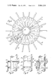
- the core or frame is comprised of a plurality of rollers spaced peripherally around an imaginary cylinder and extending parallel to the axis of the mandrel. It is preferred that the mandrel be designed so the support rollers can be easily shifted radially, and the strip length adjusted ac- Referring to FIG. 4, the beams 18 are pivotably mounted on a common center ring 19, and extend therefrom like the spokes of a wheel. The beams may be swung together by turning them about the pivot points 17, or taken off if desired. Thereby the mandrel can be folded together into a narrow shape for road transportation after disassembly of the endless strip 30, the drive chain 23, and some-of the support units.
- FIGS. 2, 3, and 4 Shown in FIGS. 2, 3, and 4 is a simple embodiment of a drive arrangement for the mandrel of FIG. 1.
- a sprocket wheel 20 On each support roller 12 is mounted a sprocket wheel 20.
- a third sprocket wheel 21 which is rotatable about a shaft 22.
- a roller chain 23 is guided around the sprockets as shown in FIGS. 3 and 4.
- the proper chain tension is maintained by means of one radially moveable tightening wheel 25 mounted on the shaft of a hydraulic motor 26.
- a variable output pump unit 27 feeds the motor 26 to cause the synchronous rotation of all support rollers with a speed that is variable between zero and maximum. Accordingly with this drive arrangement, when the mandrel diameter is changed it is only necessary to adjust the length of the roller chain 23.
- the mandrel surface 32 is formed by a series of convolutions of a continuous strip.
- strip, tape, or band are used interchangeably to mean a thin metal sheet which is relatively narrow in proportion to its length.
- the width and thickness of the strip 30, which is of a flexible but strong material, preferably steel, are determined by factors related to the particular application, including primarily the mandrel diameter.
- the strip is wound onto the mandrel core starting at the unit 33 and helically wrapped upward to form the mandrel surface.
- the strip is then taken off towards the center at the unit 34 and forms a reverse helix back through the center of the core.
- the strip continues out near the support unit 33 where it is welded to the first convolution to form an endless strip.
- the support unit 34 is lower than the others thereby allowing the strip 30 to be guided above unit 34 as it begins its return loop. Similarly, the support unit 33 is reduced in diameter in order to avoid excessive bending of the strip 30 at this point.
- the strip 30 passes closely by all truss members 16 and through individual guide units 35 provided with rollers 36.
- the guide units 35 are spaced along the respective truss members in accordance with the correct path of the strip. Proper tensioning of the endless strip is accomplished by shifting all or part of the guide units 35 upward along the sloping truss members whereby the return convolution is given a larger diameter.
- the drive unit provides for the synchronous rotation of all the support rollers 12.
- the support rollers in turn cause the continuous circulation of the helically wound strip 30, thereby providing a continuous working surface 32 on which the product is formed by any well known technique.
- the distance between support rollers is necessarily at a maximum also. Therefore, in order to prevent flat spots in the mandrel surface between support rollers, provision must be made for the proper stiffness of the strip 30. To this end it has been found particularly suitable to provide a right angle bend along one entire edge of the band as shown in FIGS. 2 and 5. The depth of the bend, like the thickness of the band, is determined by the amount of bending which the strip must endure.
- the right angle bend 37 is one suitable means for stiffening the strip 30, other means will occur to those skilled in the art and are included within the contemplation of the invention.
- One of these other stiffening means is shown in FIG. 6 wherein the strip is provided with a narrower strip 38 welded to the back of the strip along its centerline.
- a similar stiffening means could be provided by forming a lateral fold in the strip along its length.
- one particular feature of the present invention making it preferable over the prior art mandrels resides in the provision of support in the axial direction for the windings of the strip 30.
- all the support rollers 12 are provided with a number of circular grooves 40 spaced in accordance with the mandrel pitch.
- the grooves in each roller are axially displaced with respect to the corresponding grooves in an adjacent support roller so that the accumulated displacement over the entire circumference is equal to the winding pitch.
- the grooves 40 are adapted to receive the stiffening means on the endless strip 30.
- the lowermost edge of the groove then provides a support ledge 41 on which the stiffening means rides.
- the axial support ledge 41 may be provided by a series of spaced flanges 42 as shown in FIGS. 5 and 7. Still other methods of providing for the axial support of the convolutions of the strip 30 will occur to those skilled in the art.
- the strip 30 has been given a corrugation 39 along its entire length in addition to the profiled edge mentioned above. This additional feature will result in products having a helically corrugated wall giving an improved rigidity against radial deformation at a low material consumption.
- the diameter of the support rollers 12 has been reduced between the grooves 40 in order to save weight and accomodate the corrugation in the strip.
- FIG. 3 An additional modification to the basic invention is shown in FIG. 3 wherein means for internally heating the mandrel to accelerate the cure of the tubing are provided. Specifically, radiation heaters, or other thermal energy sources 50 are disposed along the entire length of each support unit. Of course it is also within the inventive concept here, that where desired, the mandrel can be used in combination with external heat sources.
- FIGS. 8-13 show a horizontally oriented mandrel embodying the invention but having additional features different from the mandrel of FIGS 1-7 and the prior art mandrels.
- this mandrel incorporates a unique combination roller drive and diameter adjustment mechanism.
- the core of the mandrel is comprised of a plurality of support units 100 disposed about the periphery of an imaginary horizontal cylinder.
- Each support unit consists of a support roller 1 12, an angular brace 116 and a base plate 114.
- Support rollers of the type shown in FIGS. 5 and 7 are preferred for this embodiment because of their lighter weight.
- the support units are assembled in cylindrical arrangement and are bolted to the large circular head plate 101.
- the headplate 101 is fixably mounted on a support frame consisting of a pair of uprights 104, cross braces 107, angular braces 105, and base members 108.
- the base members 108 extend beyond the headplate 101 to support the cantilevered mandrel.
- the headplate 101 is made rigid by a series of welded-in-place concentric rings 102 and radial ribs 103. Since the invention is particularly suitable for large diameter mandrels in the range of to 40 feet, it is anticipated that the headplate 101 would be made in sections for handling and transportation. At the manufacturing site the sections would be assembled by any suitable means such as welding or bolting. By way of example the headplate of FIG. 8 is shown as made in two sections joined along the seam indicated at 110. Since each section of the headplate is still quite large, additional braces, such as shown at 106, may be used to reinforce a section.
- a drive 150 is mounted on support 109 attached to the mandrel support frame. As discussed later, the drive 150 is adaptable to synchronously drive all of the support rollers 112.
- the forming surface of the mandrel of FIG. 9 is an endless strip 130 helically wound in abutting convolutions about the support units 100. At the free end of the mandrel the strip is coiled inward and back through the interior of the mandrel to a first convolution adjacent the headplate 101.
- the endless strip 130 is continuously circulated along its helical surface forming path and back through the center of the machine.
- the mandrel described can be used with auxiliary material applicators to form large diameter tubing of any desired length.
- each support unit is bolted to the mandrel headplate 101.
- baseplate 114 is fastened to headplate 101 by bolts 122, which extend through radially extending slots in headplate 101. Washers 123 are machined to fit in the slot in the headplate for better fastening.
- a housing is located in a central opening in the headplate 101.
- the housing 140 is fixably attached to the headplate through the welded flange 141.
- Housing 140 supports two bearings 143 which in turn support the main drive shaft 150.
- a large beveled ring gear 156 which engages a number of radially aligned beveled pinion gears 161.
- Each of the gears 161 is mounted on and keyed to the end of a radially extending shaft 160.
- the gear 161 and the inner end of shaft are supported in bearing 158.
- the bearing 158 is mounted in annular housing 159 which supports all the corresponding bearings for other support units. Housing 159 is attached to flange 141 and covers the ring gear 156.
- each of the support units 100 there is a shaft 160 mounted between the inner bearing 158 and an outer bearing 162 which is fixed to the headplate 101. As shown, the shaft 160 extends through the brace 116 and the non-rotating, hollow inner shaft 118 of roller 112. The shaft 160 is keyed and threaded for a substantial distance along its outer end for reasons to be discussed later.
- the shaft 160 also extends through bevel gear 164 and collar 165 both of which are rotatably supported by hearing 167.
- the bearing 167 is mounted in housing 166 which is permanently fixed to the baseplate 114 by any suitable means.
- the bevel gear 164 engages bevel gear 168 which is attached to support roller 112.
- Bearing 169 supports the roller 112 on shaft 118.
- roller 112 is similarly supported by a bearing attached to fixed shaft 118 and brace 116 at the free end of the mandrel.
- the bevel gear 164 is threaded internally to match the threaded portion of shaft 160.
- Gear 164 is bolted to collar 165.
- a pivotable key 171 is attached to the collar 165 by pin 172 and is adapted to engage either the slot 170 in shaft 160 or a slot in the housing 166.
- the same mechanism is used to simultaneously move the support units 100 in or out radially.
- the key 171 is pivoted out of engagement with the slot 170 in shaft 160, and into engagement with a slot in the housing 166, as shown in FIG. 10.
- the bolts 122 for each support unit are loosened to allow that unit to move relative to headplate 101.
- the support unit is secured by tightening the bolts 122.
- the pivoted key 171 on each unit is moved back into engagement with the corresponding shaft 160 and the drive system is ready for operation.
- the core of the mandrel is described as being stationary. By this it is meant that the core does not rotate along with the mandrel surface. Unlike the prior art mandrels the endless band moves relative to the core in both' the circumferential and axial directions. Thus it is understood that where the core is alsofixed to the environment, the tubing being formed must necessarily rotate with respect to the environment.
- a mandrel for the production of tubing comprising:
- a hollow core including a plurality of parallel elongated members spaced equidistantly from each other about the circumference of a circle and slideably mounted on a common headplate;
- adjustment means for simultaneously moving said elongated members radially of the circle equal distances when a change in diameter of said core is desired.
- said adjustment means comprises a rotatable drive mounted centrally of said headplate, a plurality of rotatable shafts extending radially of the circle each having means connected at one end and engaging said rotatable drive, at least a portion of each shaft being threaded, and means associated with each of said elongated members in threaded engagement with a corresponding one of said shafts whereby the member is moved radially of the circle along the shaft when the shaft rotates.
- a mandrel for the production of tubing comprising a hollow core including a plurality of parallel spaced rollers disposed equidistantly from each other about the circumference of a circle and supported by a headplate;
- adjustment means mounted on said headplate and connected to each of said rollers, the adjustment means being effective to simultaneously move said rollers radially of the circle equal distances when a change in the diameter of said core is desired.
- a mandrel for the production of tubing comprising:
- a hollow core including a plurality of parallel spaced rollers disposed equidistantly from each other about the circumference of a circle, each roller being rotatably mounted on a common headplate and movable along said headplate radially of the circle;
- a combination drive and diameter adjustment means mounted on said headplate and being selectively effective to produce either synchronous rotation of said rollers to advance said endless strip about said core or simultaneous movement of said rollers radially of the circle to change the diameter of the core.
- a mandrel as recited in claim 4, wherein said combination drive and diameter adjustment means comprises a central rotatable drive, and a plurality of radially extending mechanical transmission members each connected at one end to said central drive and at some point along its length to one of said rollers in a manner to selectively effect either rotation of the roller or movement of the roller radially of the circle when said central drive is rotated.
- said combination drive and diameter adjustment means comprises a main gear mounted centrally of said headplate, a plurality of shafts, one for each of said rollers, mounted on said headplate and extending radially of the circle, at least a portion of each shaft being threaded, each shaft having a first gear connected to one end thereof and rotatably engaging said main gear, each shaft having a second gear spaced radially outwardly of the circle from the first gear and rotatably engaging a gear on a respective one of said rollers, the second gear being threaded to mate with the threaded part of the shaft, and means for selectively locking the second gear of each shaft relatively either to the shaft in amanner such that it will rotate with the shaft and thereby rotate the respective roller, or to the respective roller in a manner such that it does not rotate with the shaft but moves longitudinally of the shaft when the shaft is rotated, whereby said rollers are simultaneously moved along said headplate radially of the circle to effect a change in
- said locking means for the second gear of each shaft is a key pivotably mounted on the second gear and adpated to engage either a slot in the shaft when rotation of the respective roller is desired or a slot in a bearing housing for the second gear when adjustment of the roller radially of the headplate is desired, the bearing housing and the roller being mounted on a baseplate movable radially of the headplate.
Landscapes
- Shaping Of Tube Ends By Bending Or Straightening (AREA)
Abstract
Description
Claims (7)
Priority Applications (1)
| Application Number | Priority Date | Filing Date | Title |
|---|---|---|---|
| US473607A US3914151A (en) | 1971-11-02 | 1974-05-28 | Mandrel for the production of reinforced plastic tubing |
Applications Claiming Priority (3)
| Application Number | Priority Date | Filing Date | Title |
|---|---|---|---|
| DK534471 | 1971-11-02 | ||
| US271309A US3861984A (en) | 1971-11-02 | 1972-07-13 | Mandrel for the production of reinforced plastic tubing |
| US473607A US3914151A (en) | 1971-11-02 | 1974-05-28 | Mandrel for the production of reinforced plastic tubing |
Publications (1)
| Publication Number | Publication Date |
|---|---|
| US3914151A true US3914151A (en) | 1975-10-21 |
Family
ID=27222084
Family Applications (1)
| Application Number | Title | Priority Date | Filing Date |
|---|---|---|---|
| US473607A Expired - Lifetime US3914151A (en) | 1971-11-02 | 1974-05-28 | Mandrel for the production of reinforced plastic tubing |
Country Status (1)
| Country | Link |
|---|---|
| US (1) | US3914151A (en) |
Cited By (15)
| Publication number | Priority date | Publication date | Assignee | Title |
|---|---|---|---|---|
| US4110149A (en) * | 1977-07-07 | 1978-08-29 | Owens-Corning Fiberglas Corporation | Rotatably driven mandrel having outer wall formed by continuously circulating endless helical band and radially adjustable support members for the band |
| US4174984A (en) * | 1978-10-02 | 1979-11-20 | Dayco Corporation | Machine for and method of making tubular conduit of indefinite length |
| US4288277A (en) * | 1979-07-17 | 1981-09-08 | Lembit Siilats | Molding system with retracting mold |
| US5945138A (en) * | 1994-04-07 | 1999-08-31 | Advanced Drainage Systems, Inc. | Cam adjustable former for plastic pipe |
| WO2000050219A1 (en) * | 1999-02-23 | 2000-08-31 | The Lamson & Sessions Co. | Conduit-making apparatus with a multiple diameter winding drum |
| US6250908B1 (en) | 1999-02-23 | 2001-06-26 | The Lamson & Sessions Co. | Conduit-making apparatus with a variable diameter winding drum |
| US20070151974A1 (en) * | 2005-12-30 | 2007-07-05 | Boyd John W | Apparatus and method for making large diameter wound-fiber reinforced tanks |
| US20130098559A1 (en) * | 2010-03-30 | 2013-04-25 | Dcns | Plant for manufacturing a rigid pipe for drawing up deep water |
| US20130252794A1 (en) * | 2011-02-07 | 2013-09-26 | Masahiro Yamasaki | Winding machine and winding method |
| DE102013208471A1 (en) * | 2013-05-08 | 2014-11-13 | Deutsches Zentrum für Luft- und Raumfahrt e.V. | Method and device for producing a molded component |
| CN105599173A (en) * | 2016-03-02 | 2016-05-25 | 东华大学 | Rigid cylindrical die with changeable outer diameter |
| WO2016129991A1 (en) * | 2015-02-09 | 2016-08-18 | Plasticon Composites International Contracting B.V. | Mandrel and method for manufacturing substantially cylindrical shaped objects |
| US9821514B2 (en) | 2012-11-20 | 2017-11-21 | Uponor Infra Oy | Method and apparatus in the manufacture of a spirally wound and welded tube |
| US9862136B2 (en) | 2012-11-20 | 2018-01-09 | Uponor Infra Oy | Method and apparatus for spirally winding a thermoplastic profile in the manufacture of welded plastic tubes |
| US20180311917A1 (en) * | 2017-04-26 | 2018-11-01 | The Boeing Company | Pultrusion systems that apply lengthwise curvature to composite parts |
Citations (3)
| Publication number | Priority date | Publication date | Assignee | Title |
|---|---|---|---|---|
| US2539853A (en) * | 1947-12-08 | 1951-01-30 | Ohio Rubber Co | Method and machine for making flexible tubing |
| US2922296A (en) * | 1959-04-29 | 1960-01-26 | Kuljian Corp | Thread processing apparatus |
| US3558411A (en) * | 1968-08-02 | 1971-01-26 | Cornelis W Beelien | Patterned articles made of filaments including segments of differing color,and method of making the same |
-
1974
- 1974-05-28 US US473607A patent/US3914151A/en not_active Expired - Lifetime
Patent Citations (3)
| Publication number | Priority date | Publication date | Assignee | Title |
|---|---|---|---|---|
| US2539853A (en) * | 1947-12-08 | 1951-01-30 | Ohio Rubber Co | Method and machine for making flexible tubing |
| US2922296A (en) * | 1959-04-29 | 1960-01-26 | Kuljian Corp | Thread processing apparatus |
| US3558411A (en) * | 1968-08-02 | 1971-01-26 | Cornelis W Beelien | Patterned articles made of filaments including segments of differing color,and method of making the same |
Cited By (24)
| Publication number | Priority date | Publication date | Assignee | Title |
|---|---|---|---|---|
| US4110149A (en) * | 1977-07-07 | 1978-08-29 | Owens-Corning Fiberglas Corporation | Rotatably driven mandrel having outer wall formed by continuously circulating endless helical band and radially adjustable support members for the band |
| US4174984A (en) * | 1978-10-02 | 1979-11-20 | Dayco Corporation | Machine for and method of making tubular conduit of indefinite length |
| US4288277A (en) * | 1979-07-17 | 1981-09-08 | Lembit Siilats | Molding system with retracting mold |
| US5945138A (en) * | 1994-04-07 | 1999-08-31 | Advanced Drainage Systems, Inc. | Cam adjustable former for plastic pipe |
| US6250908B1 (en) | 1999-02-23 | 2001-06-26 | The Lamson & Sessions Co. | Conduit-making apparatus with a variable diameter winding drum |
| US6209607B1 (en) | 1999-02-23 | 2001-04-03 | The Lamson & Sessions Co. | Conduit-making apparatus with a multiple diameter winding drum |
| WO2000050219A1 (en) * | 1999-02-23 | 2000-08-31 | The Lamson & Sessions Co. | Conduit-making apparatus with a multiple diameter winding drum |
| US20070151974A1 (en) * | 2005-12-30 | 2007-07-05 | Boyd John W | Apparatus and method for making large diameter wound-fiber reinforced tanks |
| US7481899B2 (en) * | 2005-12-30 | 2009-01-27 | Boyd John W | Apparatus and method for making large diameter wound-fiber reinforced tanks |
| US20090134158A1 (en) * | 2005-12-30 | 2009-05-28 | Boyd John W | Apparatus and method for making large diameter wound-fiber reinforced tanks |
| US7892380B2 (en) * | 2005-12-30 | 2011-02-22 | Boyd John W | Apparatus and method for making large diameter wound-fiber reinforced tanks |
| US9061475B2 (en) * | 2010-03-30 | 2015-06-23 | Dcns | Plant for manufacturing a rigid pipe for drawing up deep water |
| US20130098559A1 (en) * | 2010-03-30 | 2013-04-25 | Dcns | Plant for manufacturing a rigid pipe for drawing up deep water |
| US20130252794A1 (en) * | 2011-02-07 | 2013-09-26 | Masahiro Yamasaki | Winding machine and winding method |
| US9821514B2 (en) | 2012-11-20 | 2017-11-21 | Uponor Infra Oy | Method and apparatus in the manufacture of a spirally wound and welded tube |
| US9862136B2 (en) | 2012-11-20 | 2018-01-09 | Uponor Infra Oy | Method and apparatus for spirally winding a thermoplastic profile in the manufacture of welded plastic tubes |
| DE102013208471A1 (en) * | 2013-05-08 | 2014-11-13 | Deutsches Zentrum für Luft- und Raumfahrt e.V. | Method and device for producing a molded component |
| DE102013208471B4 (en) * | 2013-05-08 | 2015-08-20 | Deutsches Zentrum für Luft- und Raumfahrt e.V. | Method and device for producing a molded component |
| WO2016129991A1 (en) * | 2015-02-09 | 2016-08-18 | Plasticon Composites International Contracting B.V. | Mandrel and method for manufacturing substantially cylindrical shaped objects |
| NL2014266B1 (en) * | 2015-02-09 | 2016-10-13 | Plasticon Composites Int Contracting B V | Mandrel and method for manufacturing substantially cylindrical shaped objects. |
| CN105599173A (en) * | 2016-03-02 | 2016-05-25 | 东华大学 | Rigid cylindrical die with changeable outer diameter |
| CN105599173B (en) * | 2016-03-02 | 2017-10-24 | 东华大学 | A kind of rigid cylindrical mould of outer radius variable |
| US20180311917A1 (en) * | 2017-04-26 | 2018-11-01 | The Boeing Company | Pultrusion systems that apply lengthwise curvature to composite parts |
| US11065830B2 (en) * | 2017-04-26 | 2021-07-20 | The Boeing Company | Pultrusion systems that apply lengthwise curvature to composite parts |
Similar Documents
| Publication | Publication Date | Title |
|---|---|---|
| US3914151A (en) | Mandrel for the production of reinforced plastic tubing | |
| US4575400A (en) | Apparatus for manufacturing corrugated tubes | |
| US4597276A (en) | Apparatus for making helically wound interlocked tubular structure | |
| US2502638A (en) | Method of extruding plastics in tubular form and wrapping the tubing | |
| FI85230B (en) | ROTERINGSMASKIN FOER SPIRALFORMIGT UTGJORT ROER. | |
| RU2087301C1 (en) | Method of helical cutting of tubular material | |
| US4077828A (en) | Machine for manufacturing reinforced tubes | |
| US4012272A (en) | Apparatus for making reinforced flexible hose | |
| KR100938020B1 (en) | The manufacture apparatus of fiberglass reinforced plastic | |
| CN104441672B (en) | Plastic corrugated pipe with steel belt reinforcing bodies as well as process and equipment for manufacturing same | |
| US3861984A (en) | Mandrel for the production of reinforced plastic tubing | |
| US3130104A (en) | Apparatus for continuously manufacturing fiber reinforced plastic pipe | |
| US3548724A (en) | Apparatus and method for forming indefinite length tubular articles | |
| CA1295538C (en) | Apparatus for producing a wound plastic tube | |
| JPH01156041A (en) | Pipe manufacturing machine | |
| US2948200A (en) | Method and apparatus for winding and cementing tubes or hose | |
| CA2127810C (en) | Corrugated pipe manufacturing apparatus | |
| US4603799A (en) | Forward feed assembly for continuous forward feed of open tubular fabric under controlled tension | |
| US2893296A (en) | Apparatus for winding tubes | |
| US1999151A (en) | Pipe wrapping machine | |
| US2693779A (en) | Machine for making round flexible metal tubes | |
| CN1238739A (en) | Capstan arrangement for cable treatment plant | |
| US2963233A (en) | Traversing reel | |
| CN215750894U (en) | Steel skeleton polyolefin pipeline and production device thereof | |
| US3308001A (en) | Apparatus for winding hollow articles |
Legal Events
| Date | Code | Title | Description |
|---|---|---|---|
| AS | Assignment |
Owner name: WILMINGTON TRUST COMPANY, ONE RODNEY SQUARE NORTH, Free format text: SECURITY INTEREST;ASSIGNOR:OWENS-CORNING FIBERGLAS CORPORATION;REEL/FRAME:004652/0351 Effective date: 19861103 Owner name: WADE, WILLIAM, J., ONE RODNEY SQUARE NORTH, WILMIN Free format text: SECURITY INTEREST;ASSIGNOR:OWENS-CORNING FIBERGLAS CORPORATION;REEL/FRAME:004652/0351 Effective date: 19861103 Owner name: WILMINGTON TRUST COMPANY, DELAWARE Free format text: SECURITY INTEREST;ASSIGNOR:OWENS-CORNING FIBERGLAS CORPORATION;REEL/FRAME:004652/0351 Effective date: 19861103 Owner name: WADE, WILLIAM, J., DELAWARE Free format text: SECURITY INTEREST;ASSIGNOR:OWENS-CORNING FIBERGLAS CORPORATION;REEL/FRAME:004652/0351 Effective date: 19861103 |
|
| AS | Assignment |
Owner name: OWENS-CORNING FIBERGLAS CORPORATION, FIBERGLAS TOW Free format text: TERMINATION OF SECURITY AGREEMENT RECORDED NOV. 13, 1986. REEL 4652 FRAMES 351-420;ASSIGNORS:WILMINGTON TRUST COMPANY, A DE. BANKING CORPORATION;WADE, WILLIAM J. (TRUSTEES);REEL/FRAME:004903/0501 Effective date: 19870730 Owner name: OWENS-CORNING FIBERGLAS CORPORATION, A CORP. OF DE Free format text: TERMINATION OF SECURITY AGREEMENT RECORDED NOV. 13, 1986. REEL 4652 FRAMES 351-420;ASSIGNORS:WILMINGTON TRUST COMPANY, A DE. BANKING CORPORATION;WADE, WILLIAM J. (TRUSTEES);REEL/FRAME:004903/0501 Effective date: 19870730 |
|
| AS | Assignment |
Owner name: OWENS-CORNING FIBERGLAS TECHNOLOGY INC., ILLINOIS Free format text: ASSIGNMENT OF ASSIGNORS INTEREST.;ASSIGNOR:OWENS-CORNING FIBERGLAS CORPORATION, A CORP. OF DE;REEL/FRAME:006041/0175 Effective date: 19911205 |