US3901159A - Tamping tool head - Google Patents
Tamping tool head Download PDFInfo
- Publication number
- US3901159A US3901159A US453521A US45352174A US3901159A US 3901159 A US3901159 A US 3901159A US 453521 A US453521 A US 453521A US 45352174 A US45352174 A US 45352174A US 3901159 A US3901159 A US 3901159A
- Authority
- US
- United States
- Prior art keywords
- hole
- drive shaft
- tapering
- tool head
- attachment portion
- Prior art date
- Legal status (The legal status is an assumption and is not a legal conclusion. Google has not performed a legal analysis and makes no representation as to the accuracy of the status listed.)
- Expired - Lifetime
Links
- 239000011435 rock Substances 0.000 description 3
- 239000004519 grease Substances 0.000 description 2
- 230000009471 action Effects 0.000 description 1
- 230000008859 change Effects 0.000 description 1
- 230000008878 coupling Effects 0.000 description 1
- 238000010168 coupling process Methods 0.000 description 1
- 238000005859 coupling reaction Methods 0.000 description 1
- 230000006872 improvement Effects 0.000 description 1
- 238000000034 method Methods 0.000 description 1
- 230000008569 process Effects 0.000 description 1
Images


Classifications
-
- E—FIXED CONSTRUCTIONS
- E01—CONSTRUCTION OF ROADS, RAILWAYS, OR BRIDGES
- E01B—PERMANENT WAY; PERMANENT-WAY TOOLS; MACHINES FOR MAKING RAILWAYS OF ALL KINDS
- E01B27/00—Placing, renewing, working, cleaning, or taking-up the ballast, with or without concurrent work on the track; Devices therefor; Packing sleepers
- E01B27/12—Packing sleepers, with or without concurrent work on the track; Compacting track-carrying ballast
- E01B27/13—Packing sleepers, with or without concurrent work on the track
- E01B27/16—Sleeper-tamping machines
Definitions
- This hole is adapted to receive the tapering end of the drive shaft and locking means are provided to lock the attachment portion to the tapering end.
- the tapering surfaces defining the hole are shaped to bear against the tapering surfaces of the end of the drive shaft when the head is mounted to the end.
- TAMPING TOOL HEAD This invention relates to tamping tools for railroad beds and in particular to tamping tool heads.
- Power equipment for consolidating the ballast of a railway track under the ties thereof is well known in the industry and has been used for many years.
- One embodiment of this equipment uses rapidly vibrating tamping forks which can be lowered into the roadbed to compact the ballast. It is known for example to use a tamping fork with a pair of downwardly extending spaced apart arms, each arm having a small plate at its bottom end which assists in the tamping process.
- a drive shaft which is pivotally mounted in a housing. The pair of arms is rigidly attached to the bottom of this shaft and the top of the shaft is rigidly connected to a short rocker arm.
- the rocker arm is pivotally connected to a somewhat longer connecting rod which is in its turn conventionally connected to an eccentric of a crank shaft.
- the crank shaft is connected to an electric motor (for example) which revolves at high speed causing the aforementioned drive shaft to rock clockwise and counterclockwise at high speed and at low amplitude. This motion is imparted to the fork arms whereby a high frequency low amplitude tamping vibration is set up in the fork arms.
- the present invention is directed to an improvement inthese fork arms themselves and in particular the means for connecting the arms to the bottom of the drive shaft.
- each fork arm has been connected to one arm of a separate connecting member having two, generally horizontally-extending, connecting arms. These connecting arms extend outwardly from a central portion having a hole therein to receive the bottom end of the drive shaft which is rigidly fastened in this hole.
- Each fork arm was formed with a threaded upper portion which was inserted from the bottom through a further hole formed in each connecting arm so that the upper end of the threaded portion protruded from the top end of the hole. A nut or two was then threaded onto this upper end to secure the fork arm to the connecting member.
- Such fork arms and connecting members are for example shown in British Patent 1,008,785 dated July 2, 1969.
- the tamping arms of course tend to wear out fairly quickly, at least relative to the rest of the tamping machine and therefore must be replaced from time to time. Sometimes this replacement must be done at the location where the machine is working, particularly if one of the arms should break as sometime occurs, and in such cases the best equipment might not be available to the operator of the machine to change the fork arms. It will also be appreciated that time wasted in replacing the fork arms is valuable time because tamping machines are generally expensive and operators wages are increasing all the time. The railroad industry is of course constantly seeking ways of avoiding or lessening the down time of such equipment.
- the tamping tool head is mounted on an end of a tamping tool drive shaft, the end having a conical, downward taper.
- the tool head comprises a pair of fork arms connected to a center attachment portion having a conically and downwardly tapering hole.
- the center attachment portion is formed integrally with the pair of fork arms.
- This hole is adapted to receive the tapering end of the drive shaft and locking means are provided to lock the attachment portion to the tapering end.
- the tapering surfaces defining the hole are shaped to bear against the tapering surfaces of the end of the drive shaft when the head is mounted to the end.
- the locking means is preferably a single bolt which is threaded into ahole in the end of the shaft.
- the tapering surface of the hole in the attachment portion is split into two surfaces by a recess extending about the circumference of the hole at the vertical center thereof.
- FIG. 1 is a plan view partially in section of the con-' necting rod, rocker arm, and associated housing therefor for vibrating the temping tool heads of the present invention taken on the section line I-I of FIG. 2;
- FIG. 2 is a cross-sectional elevation of a tamping unit taken on section line IIII of FIG. 1;
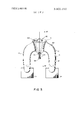
- FIG. 3 is a perspective view of the tamping tool head of the present invention.
- FIG. 4 is a sectional view taken along the line IV-IV of FIG. 3 of one preferred embodiment of the tool head.
- the tamping unit is designated generally in the drawings by the numeral 10 and the unit preferably has means for vibrating two tamping heads 11 of the present invention, only one of which is shown in FIG. 2.
- the portions of the tamping machine not shown in the drawings or described herein are well known in the art and need not be described.
- the tamping tool head 11 has a pair of fork arms 12 connected to a center attachment portion 13.
- the two tool heads 11 of the tamping unit are arranged so as to be spaced apart from each other on the housing 14 of the tamping unit. Extending above, centrally, and longitudinally of each tool head 11 is a drive shaft which is mounted in the housing 14 in roller races 16.
- each drive shaft 15 is rigidly attached to and surrounded by a collar 17 from which extends a bifurcated rocker arm 18.
- Each rocker arm 18 is pivotally connected to a connecting rod 19 which in turn is conventionally connected to an eccentric of a central crank shaft 20.
- the crank shaft is mounted in the housing 14 in roller races and its pair of eccentries 26 and 27 are of small throw and spaced apart 180.
- the crank shaft 20 is connected though a coupling 28 with the drive shaft 29 of an electric motor 30.
- the electric motor revolves at high speed driving the crank shaft 20 which through the connecting rods 19 and rocker arms 18 rocks the drive shafts 15 clockwise and counter-clockwise at high speed and at low amplitude.
- This motion is imparted to the fork arms 12 whereby a high frequency low amplitude tamping vibration is set up in the fork arms 12 which rock clockwise and counter-clockwise with the drive shaft
- the drive shaft 15 is preferably lubricated with grease or oil to prevent undue wear as it rotates rapidly in its housing. Seals 50 are therefore preferably provided to contain this grease or oil. These seals tend to wear out due to the vibrations of the tamping unit and normal wear and tear and thus must be replaced from time to time. In order to do this, the tool head 11 is normally removed.
- the tamping tool head 11 of the present invention is mounted to the bottom end 31 of the drive shaft 15, this end having a conical and downward taper as can be seen from the right side of FIG. 2 wherein the tool head has been removed.
- the tapering end is provided with a generally vertical keyway or groove 21 of rectangular cross-section for a key used in mounting the tool head 11.
- the center attachment portion 13 has a conically and downwardly tapering hole 32 which is shown in dotted lines and is adapted to receive the tapering end 31 of the drive shaft 15.
- the tapering serfaces defining the hole 32 have the same taper as the end 31 of the drive shaft and thus bear snuggly against the tapering surfaces of the end 31 when the tool head is mounted to the end 31 of the drive shaft.
- the hole 32 has a keyway or groove 22 of rectangular cross-section on one side extending from the top to the bottom of the hole 32. The groove is for a key used in mounting the tool head.
- Locking means 33 are provided for locking or fastening the center attachment portion 13 to the tapering end 31.
- the locking means 33 includes a single threaded bolt 34 and a washer 35 can also be employed if desired.
- the end 31 is merely inserted into the hole 32 as far as it will go and then the bolt 34 is inserted through the washer 35 and screwed into a generally vertically oriented threaded hole formed in the bottom of the end 31.
- the groove 21 in end 31 is brought into alignment with groove 22 in the hole 32 so that the two are directly opposite each other.
- a key (not shown) is then inserted into the hole formed by the combined grooves to stop any pivotal movement of the tool head.
- the tamping tool head is fitted with two tamping plates 41, one plate being at the end of each fork arm 12.
- These plates can have a rectangular shape as shown and can be rigidly attached to the rear or front surface of the fork arm 12.
- the preferred embodiment of the tool head shown in FIG. 3 is formed with generally L-shaped fork arms 12, each consisting of a relatively long vertical portion 42 and a relatively short, generally horizontal portion 43.
- the center attachment portion 13 has a circular horizontal cross-section from top to bottom and its outer surfaces are tapered in a manner similar to the walls forming the hole 32.
- the center attachment portion 13 is formed integrally with the two fork arms 12 so that it is not necessary to form each fork arm 12 with a threaded portion or to attach each fork arm to the attachment portion 13 by means of a nut or other type of fastener.
- the attachment means shown for connecting the tool head 11 to the drive shaft 15 has considerable advantages over the attachment means used in the prior art. Besides those already discussed, it should be noted that once the bolt 34 has been removed the tool head 11 will always slip easily off of the end 31 because the contacting surfaces between the end 31 and the attachment portion 13 have a downward taper. If the end 31 and hole 32 had no taper but were formed with parallel sides, it is possible that the tool head 11 might become jammed on the end 31 due to the vibrations of the machine or otherwise. Secondly, it will readily be recognized that, as the contacting surfaces of the tool head 11 and end 31 become worn from use, neither the tool head 11 nor the drive shaft 15 need necessarily be replaced (provided the rest of the tool head has not become unduly worn).
- FIG. 4 An alternative form of hole 32 in the attachment portion 13 is shown in FIG. 4 wherein the hole 32 still has conically and downwardly tapering surfaces but the center portion of the hole has a recess 45 extending completely around the circumference of the hole.
- the recess 45 has a substantially rectangular cross-section and a width from top to bottom equal approximately to half the over all height of the hole 32.
- this arrangement ensures that there will always be at least two spaced-apart contacting surfaces of the tool head. This in turn will prevent the tool head from rocking relative to the drive shaft 15 as the machine is used. Such rocking of course is undesirable as it may cause the tool head or drive shaft to become worn out prematurely.
- a tamping tool head for mounting to an end of a tamping tool drive shaft having a conically and downwardly tapering end which tool head comprises a pair of fork arms connected to a center attachment portion, said center attachment portion being formed integrally with said pair of fork arms, a hole having a conically downwardly tapering surface in said center attachment portion and adapted to receive the tapering end of said drive shaft, and locking means for locking said attachment portion to said tapering end, wherein the tapering surface of said hole is shaped to bear against the tapering surface of the end of said drive shaft when said head is mounted to said end.
- a tamping tool head according to claim 2 wherein said tapering end of said drive shaft has a generally vertically oriented threaded hole therein adapted to receive said single bolt.
- a tamping tool head for mounting to an end of a tamping tool drive shaft having a conically and downwardly tapering end which too] head comprises a pair of fork arms connected to a center attachment portion, a hole having a conically downwardly tapering surface in said center attachment portion and adapted to receive the tapering end of said drive shaft, and locking means for locking said attachment portion to said tapering end, wherein the tapering surface of said hole is shaped to bear against the tapering surface of the end of said drive shaft when said head is mounted to said end and wherein said tapering surface of said hole is split into two surfaces by a recess extending about the circumference of said hole at the vertical center thereof.
- a tamping tool head according to claim 4 wherein said recess has a width from top to bottom approximately one-half of the height of said hole.
- a tamping tool head for mounting to an end of a tamping tool drive shaft having a conically and downwardly tapering end which tool head comprises a pair of fork arms connected to a center attachment portion, said center attachment portion being formed integrally with said pair of fork arms, a hole having a conically downwardly tapering surface in said center attachment portion and adapted to receive the tapering end of said drive shaft, and locking means for locking said attachment portion to said tapering end, and a keyway groove formed in one side of said hole and extending generally vertically therein, said groove being adapted to receive a key when said tool head is mounted on said drive shaft and thereby prevent said tool head from pivoting about the center axis of said drive shaft, wherein the tapering surface of said hole is shaped to bear against the tapering surface of the end of said drive shaft when said head is mounted to said end.
Landscapes
- Engineering & Computer Science (AREA)
- Architecture (AREA)
- Civil Engineering (AREA)
- Structural Engineering (AREA)
- Machines For Laying And Maintaining Railways (AREA)
Abstract
A tamping tool head for mounting to an end of a tamping tool drive shaft having a conically and downwardly tapering end. The tool head comprises a pair of fork arms connected to a center attachment portion having a conically and downwardly tapering hole. This hole is adapted to receive the tapering end of the drive shaft and locking means are provided to lock the attachment portion to the tapering end. The tapering surfaces defining the hole are shaped to bear against the tapering surfaces of the end of the drive shaft when the head is mounted to the end.
Description
United States Patent Von Beckmann [451 Aug. 26, 1975 TAMPING TOOL HEAD [75] Inventor: Helmuth Von Beckmann, Columbia,
[73] Assignee: Canron Inc., Phillipsburg, NJ.
[22] Filed: Mar. 21, 1974 [21] Appl. No.: 453,521
[52] U.S. Cl. 104/12 [Sl] Int. Cl. E01B 27/00 [58] Field of Search 104/8, 9, 10, ll, 12, 13
[56] References Cited UNITED STATES PATENTS 2,497,682 2/1950 Mertz 104/12 2,607,569 8/1952 Pierre lO4/13 2,973,719 3/l96l Plasser et a1. 104/12 29- I so Primary Examiner-Lloyd L. King Assistant Exa'miner-Richard A. Bertsch 5 7 ABSTRACT A tamping tool head for mounting to an end of a tamping tool drive shaft having a conically and downwardly tapering end. The tool head comprises a pair of fork arms connected to a center attachment portion having a conically and downwardly tapering hole. This hole is adapted to receive the tapering end of the drive shaft and locking means are provided to lock the attachment portion to the tapering end. The tapering surfaces defining the hole are shaped to bear against the tapering surfaces of the end of the drive shaft when the head is mounted to the end.
6 Claims, 4 Drawing Figures PATENTED Z 3,901,159
321m 2 [IF 3 FIG. 3
PATENTEDAUGZSIQE 3 901 159 SHEET 3 UP 3 FIG. 4
TAMPING TOOL HEAD This invention relates to tamping tools for railroad beds and in particular to tamping tool heads.
BACKGROUND OF THE INVENTION Power equipment for consolidating the ballast of a railway track under the ties thereof is well known in the industry and has been used for many years. One embodiment of this equipment uses rapidly vibrating tamping forks which can be lowered into the roadbed to compact the ballast. It is known for example to use a tamping fork with a pair of downwardly extending spaced apart arms, each arm having a small plate at its bottom end which assists in the tamping process. Extending above, centrally and longitudinally of this pair of arms is a drive shaft which is pivotally mounted in a housing. The pair of arms is rigidly attached to the bottom of this shaft and the top of the shaft is rigidly connected to a short rocker arm. The rocker arm is pivotally connected to a somewhat longer connecting rod which is in its turn conventionally connected to an eccentric of a crank shaft. The crank shaft is connected to an electric motor (for example) which revolves at high speed causing the aforementioned drive shaft to rock clockwise and counterclockwise at high speed and at low amplitude. This motion is imparted to the fork arms whereby a high frequency low amplitude tamping vibration is set up in the fork arms.
The present invention is directed to an improvement inthese fork arms themselves and in particular the means for connecting the arms to the bottom of the drive shaft. In the past, each fork arm has been connected to one arm of a separate connecting member having two, generally horizontally-extending, connecting arms. These connecting arms extend outwardly from a central portion having a hole therein to receive the bottom end of the drive shaft which is rigidly fastened in this hole. Each fork arm was formed with a threaded upper portion which was inserted from the bottom through a further hole formed in each connecting arm so that the upper end of the threaded portion protruded from the top end of the hole. A nut or two was then threaded onto this upper end to secure the fork arm to the connecting member. Such fork arms and connecting members are for example shown in British Patent 1,008,785 dated July 2, 1969.
The tamping arms of course tend to wear out fairly quickly, at least relative to the rest of the tamping machine and therefore must be replaced from time to time. Sometimes this replacement must be done at the location where the machine is working, particularly if one of the arms should break as sometime occurs, and in such cases the best equipment might not be available to the operator of the machine to change the fork arms. It will also be appreciated that time wasted in replacing the fork arms is valuable time because tamping machines are generally expensive and operators wages are increasing all the time. The railroad industry is of course constantly seeking ways of avoiding or lessening the down time of such equipment.
Another problem encountered by the industry in connection with tamping heads and the means for vibrating these heads is the fact that the various seals for the drive shafts wear out from time to time due to the vibrations in such equipment and natural wear and tear. In order to replace these seals, the tamping forks must often be removed and this takes time and may be difficult with present equipment.
Accordingly it is an object of the present invention to provide a tamping took head which can be quickly and easily replaced when worn or broken.
It is a further object of the present invention to provide a tamping head having a pair of fork arms wherein both arms canbe replaced by single, easy step using ordinary tools.
It is another object of the invention to provide a tamping head which can be easily removed for replacement of seals and other parts comprising the tamping tool.
SUMMARY OF THE INVENTION The tamping tool head according to one aspect of the invention is mounted on an end of a tamping tool drive shaft, the end having a conical, downward taper. The tool head comprises a pair of fork arms connected to a center attachment portion having a conically and downwardly tapering hole. The center attachment portion is formed integrally with the pair of fork arms. This hole is adapted to receive the tapering end of the drive shaft and locking means are provided to lock the attachment portion to the tapering end. The tapering surfaces defining the hole are shaped to bear against the tapering surfaces of the end of the drive shaft when the head is mounted to the end.
The locking means is preferably a single bolt which is threaded into ahole in the end of the shaft. According to another aspect of the invention, the tapering surface of the hole in the attachment portion is split into two surfaces by a recess extending about the circumference of the hole at the vertical center thereof.
A preferred embodiment of the present invention will to the accompanying drawings.
BRIEF DESCRIPTION OF THE DRAWINGS In the drawings:
FIG. 1 is a plan view partially in section of the con-' necting rod, rocker arm, and associated housing therefor for vibrating the temping tool heads of the present invention taken on the section line I-I of FIG. 2;
FIG. 2 is a cross-sectional elevation of a tamping unit taken on section line IIII of FIG. 1;
FIG. 3 is a perspective view of the tamping tool head of the present invention; and
, FIG. 4 is a sectional view taken along the line IV-IV of FIG. 3 of one preferred embodiment of the tool head.
DETAILED-DESCRIPTION OF PREFERRED EMBODIMENT The tamping unit is designated generally in the drawings by the numeral 10 and the unit preferably has means for vibrating two tamping heads 11 of the present invention, only one of which is shown in FIG. 2. The portions of the tamping machine not shown in the drawings or described herein are well known in the art and need not be described. The tamping tool head 11 has a pair of fork arms 12 connected to a center attachment portion 13. The two tool heads 11 of the tamping unit are arranged so as to be spaced apart from each other on the housing 14 of the tamping unit. Extending above, centrally, and longitudinally of each tool head 11 is a drive shaft which is mounted in the housing 14 in roller races 16.
The upper end of each drive shaft 15 is rigidly attached to and surrounded by a collar 17 from which extends a bifurcated rocker arm 18. Each rocker arm 18 is pivotally connected to a connecting rod 19 which in turn is conventionally connected to an eccentric of a central crank shaft 20. The crank shaft is mounted in the housing 14 in roller races and its pair of eccentries 26 and 27 are of small throw and spaced apart 180. The crank shaft 20 is connected though a coupling 28 with the drive shaft 29 of an electric motor 30.
In operation the electric motor revolves at high speed driving the crank shaft 20 which through the connecting rods 19 and rocker arms 18 rocks the drive shafts 15 clockwise and counter-clockwise at high speed and at low amplitude. This motion is imparted to the fork arms 12 whereby a high frequency low amplitude tamping vibration is set up in the fork arms 12 which rock clockwise and counter-clockwise with the drive shaft The drive shaft 15 is preferably lubricated with grease or oil to prevent undue wear as it rotates rapidly in its housing. Seals 50 are therefore preferably provided to contain this grease or oil. These seals tend to wear out due to the vibrations of the tamping unit and normal wear and tear and thus must be replaced from time to time. In order to do this, the tool head 11 is normally removed.
The tamping tool head 11 of the present invention is mounted to the bottom end 31 of the drive shaft 15, this end having a conical and downward taper as can be seen from the right side of FIG. 2 wherein the tool head has been removed. The tapering end is provided with a generally vertical keyway or groove 21 of rectangular cross-section for a key used in mounting the tool head 11.
The preferred embodiment of the tool head 11 of the present invention is best seen in FIG. 3 of the drawings. The center attachment portion 13 has a conically and downwardly tapering hole 32 which is shown in dotted lines and is adapted to receive the tapering end 31 of the drive shaft 15. The tapering serfaces defining the hole 32 have the same taper as the end 31 of the drive shaft and thus bear snuggly against the tapering surfaces of the end 31 when the tool head is mounted to the end 31 of the drive shaft. The hole 32 has a keyway or groove 22 of rectangular cross-section on one side extending from the top to the bottom of the hole 32. The groove is for a key used in mounting the tool head.
Locking means 33 are provided for locking or fastening the center attachment portion 13 to the tapering end 31. Preferably, the locking means 33 includes a single threaded bolt 34 and a washer 35 can also be employed if desired. In order to mount the tamping tool head to the end 31 of the drive shaft then, the end 31 is merely inserted into the hole 32 as far as it will go and then the bolt 34 is inserted through the washer 35 and screwed into a generally vertically oriented threaded hole formed in the bottom of the end 31.
In order to prevent the tool head from pivoting about the center axis of end 31, the groove 21 in end 31 is brought into alignment with groove 22 in the hole 32 so that the two are directly opposite each other. A key (not shown) is then inserted into the hole formed by the combined grooves to stop any pivotal movement of the tool head.
Preferably the tamping tool head is fitted with two tamping plates 41, one plate being at the end of each fork arm 12. These plates can have a rectangular shape as shown and can be rigidly attached to the rear or front surface of the fork arm 12.
The preferred embodiment of the tool head shown in FIG. 3 is formed with generally L-shaped fork arms 12, each consisting of a relatively long vertical portion 42 and a relatively short, generally horizontal portion 43. The center attachment portion 13 has a circular horizontal cross-section from top to bottom and its outer surfaces are tapered in a manner similar to the walls forming the hole 32. The center attachment portion 13 is formed integrally with the two fork arms 12 so that it is not necessary to form each fork arm 12 with a threaded portion or to attach each fork arm to the attachment portion 13 by means of a nut or other type of fastener.
The attachment means shown for connecting the tool head 11 to the drive shaft 15 has considerable advantages over the attachment means used in the prior art. Besides those already discussed, it should be noted that once the bolt 34 has been removed the tool head 11 will always slip easily off of the end 31 because the contacting surfaces between the end 31 and the attachment portion 13 have a downward taper. If the end 31 and hole 32 had no taper but were formed with parallel sides, it is possible that the tool head 11 might become jammed on the end 31 due to the vibrations of the machine or otherwise. Secondly, it will readily be recognized that, as the contacting surfaces of the tool head 11 and end 31 become worn from use, neither the tool head 11 nor the drive shaft 15 need necessarily be replaced (provided the rest of the tool head has not become unduly worn). When this wearing action has taken place and the attachment portion becomes loose due to the wear, the end 31 need only be pushed further into the hole 32 so that the slack between the attachment portion 13 and end 31 is removed and the bolt 34 threaded further into the hole 40 so that it is tight.
An alternative form of hole 32 in the attachment portion 13 is shown in FIG. 4 wherein the hole 32 still has conically and downwardly tapering surfaces but the center portion of the hole has a recess 45 extending completely around the circumference of the hole. The recess 45 has a substantially rectangular cross-section and a width from top to bottom equal approximately to half the over all height of the hole 32. Thus, with this tool head, the end 31 of the shaft bears against the attachment portion 13 only in the top section and in the bottom section of the hole 32. This type of hole is advantageous in that it prevents the shaft from contacting only a small center portion of the surfaces of the hole 32 either because of the way in which shaft end and hole were originally machined or cast or because of the wearing away of the contacting surfaces as the tool head is used. In other Words this arrangement ensures that there will always be at least two spaced-apart contacting surfaces of the tool head. This in turn will prevent the tool head from rocking relative to the drive shaft 15 as the machine is used. Such rocking of course is undesirable as it may cause the tool head or drive shaft to become worn out prematurely.
What I claim as my invention is:
l. A tamping tool head for mounting to an end of a tamping tool drive shaft having a conically and downwardly tapering end which tool head comprises a pair of fork arms connected to a center attachment portion, said center attachment portion being formed integrally with said pair of fork arms, a hole having a conically downwardly tapering surface in said center attachment portion and adapted to receive the tapering end of said drive shaft, and locking means for locking said attachment portion to said tapering end, wherein the tapering surface of said hole is shaped to bear against the tapering surface of the end of said drive shaft when said head is mounted to said end.
2. A tamping tool head according to claim 1 wherein said locking means is a single bolt.
3. A tamping tool head according to claim 2 wherein said tapering end of said drive shaft has a generally vertically oriented threaded hole therein adapted to receive said single bolt.
4. A tamping tool head for mounting to an end of a tamping tool drive shaft having a conically and downwardly tapering end which too] head comprises a pair of fork arms connected to a center attachment portion, a hole having a conically downwardly tapering surface in said center attachment portion and adapted to receive the tapering end of said drive shaft, and locking means for locking said attachment portion to said tapering end, wherein the tapering surface of said hole is shaped to bear against the tapering surface of the end of said drive shaft when said head is mounted to said end and wherein said tapering surface of said hole is split into two surfaces by a recess extending about the circumference of said hole at the vertical center thereof.
5. A tamping tool head according to claim 4 wherein said recess has a width from top to bottom approximately one-half of the height of said hole.
6. A tamping tool head for mounting to an end of a tamping tool drive shaft having a conically and downwardly tapering end which tool head comprises a pair of fork arms connected to a center attachment portion, said center attachment portion being formed integrally with said pair of fork arms, a hole having a conically downwardly tapering surface in said center attachment portion and adapted to receive the tapering end of said drive shaft, and locking means for locking said attachment portion to said tapering end, and a keyway groove formed in one side of said hole and extending generally vertically therein, said groove being adapted to receive a key when said tool head is mounted on said drive shaft and thereby prevent said tool head from pivoting about the center axis of said drive shaft, wherein the tapering surface of said hole is shaped to bear against the tapering surface of the end of said drive shaft when said head is mounted to said end.
Claims (6)
1. A tamping tool head for mounting to an end of a tamping tool drive shaft having a conically and downwardly tapering end which tool head comprises a pair of fork arms connected to a center attachment portion, said center attachment portion being formed integrally with said pair of fork arms, a hole having a conically downwardly tapering surface in said center attachment portion and adapted to receive the tapering end of said drive shaft, and locking means for locking said attachment portion to said tapering end, wherein the tapering surface of said hole is shaped to bear against the tapering surface of the end of said drive shaft when said head is mounted to said end.
2. A tamping tool head according to claim 1 wherein said locking means is a single bolt.
3. A tamping tool head according to claim 2 wherein said tapering end of said drive shaft has a generally vertically oriented threaded hole therein adapted to receive said single bolt.
4. A tamping tool head for mounting to an end of a tamping tool drive shaft having a conically and downwardly tapering end which tool head comprises a pair of fork arms connected to a center attachment portion, a hole having a conically downwardly tapering surface in said center attachment portion and adapted to receive the tapering end of said drive shaft, and locking means for locking said attachment portion to said tapering end, wherein the tapering surface of said hole is shaped to bear against the tapering surface of the end of said drive shaft when said head is mounted to said end and wherein said tapering surface of said hole is split into two surfaces by a recess extending about the circumference of said hole at the vertical center thereof.
5. A tamping tool head according to claim 4 wherein said recess haS a width from top to bottom approximately one-half of the height of said hole.
6. A tamping tool head for mounting to an end of a tamping tool drive shaft having a conically and downwardly tapering end which tool head comprises a pair of fork arms connected to a center attachment portion, said center attachment portion being formed integrally with said pair of fork arms, a hole having a conically downwardly tapering surface in said center attachment portion and adapted to receive the tapering end of said drive shaft, and locking means for locking said attachment portion to said tapering end, and a keyway groove formed in one side of said hole and extending generally vertically therein, said groove being adapted to receive a key when said tool head is mounted on said drive shaft and thereby prevent said tool head from pivoting about the center axis of said drive shaft, wherein the tapering surface of said hole is shaped to bear against the tapering surface of the end of said drive shaft when said head is mounted to said end.
Priority Applications (5)
| Application Number | Priority Date | Filing Date | Title |
|---|---|---|---|
| US453521A US3901159A (en) | 1974-03-21 | 1974-03-21 | Tamping tool head |
| CA221,008A CA1030014A (en) | 1974-03-21 | 1975-02-28 | Tamping tool head |
| AU79059/75A AU498931B2 (en) | 1974-03-21 | 1975-03-13 | Tamping tool head |
| AR258025A AR203786A1 (en) | 1974-03-21 | 1975-03-18 | A RAMMER TOOL HEAD |
| BR1706/75A BR7501706A (en) | 1974-03-21 | 1975-03-21 | IMPROVEMENT IN PUNCH TOOL HEAD |
Applications Claiming Priority (1)
| Application Number | Priority Date | Filing Date | Title |
|---|---|---|---|
| US453521A US3901159A (en) | 1974-03-21 | 1974-03-21 | Tamping tool head |
Publications (1)
| Publication Number | Publication Date |
|---|---|
| US3901159A true US3901159A (en) | 1975-08-26 |
Family
ID=23800884
Family Applications (1)
| Application Number | Title | Priority Date | Filing Date |
|---|---|---|---|
| US453521A Expired - Lifetime US3901159A (en) | 1974-03-21 | 1974-03-21 | Tamping tool head |
Country Status (5)
| Country | Link |
|---|---|
| US (1) | US3901159A (en) |
| AR (1) | AR203786A1 (en) |
| AU (1) | AU498931B2 (en) |
| BR (1) | BR7501706A (en) |
| CA (1) | CA1030014A (en) |
Cited By (5)
| Publication number | Priority date | Publication date | Assignee | Title |
|---|---|---|---|---|
| US4167141A (en) * | 1977-05-11 | 1979-09-11 | Haywood Glen H | Percussive tool with replaceable work bit |
| US4598645A (en) * | 1981-12-10 | 1986-07-08 | Sig Societe Industrielle Suisse | Railway track tamper |
| US5730059A (en) * | 1995-03-22 | 1998-03-24 | Harsco Corporation | Split tool mechanical vibrator |
| EP1172480A3 (en) * | 2000-07-12 | 2003-07-16 | Harsco Technologies Corporation | Split tool tamper |
| WO2018202380A1 (en) * | 2017-05-03 | 2018-11-08 | Plasser & Theurer Export Von Bahnbaumaschinen Gmbh | Tamping unit for tamping sleepers of a track |
Citations (3)
| Publication number | Priority date | Publication date | Assignee | Title |
|---|---|---|---|---|
| US2497682A (en) * | 1950-02-14 | Railroad ballast tamper and equalizer | ||
| US2607569A (en) * | 1944-03-16 | 1952-08-19 | Pierre Bernard | Concrete tamping device |
| US2973719A (en) * | 1960-01-28 | 1961-03-07 | Plasser Franz | Track tamper |
-
1974
- 1974-03-21 US US453521A patent/US3901159A/en not_active Expired - Lifetime
-
1975
- 1975-02-28 CA CA221,008A patent/CA1030014A/en not_active Expired
- 1975-03-13 AU AU79059/75A patent/AU498931B2/en not_active Expired
- 1975-03-18 AR AR258025A patent/AR203786A1/en active
- 1975-03-21 BR BR1706/75A patent/BR7501706A/en unknown
Patent Citations (3)
| Publication number | Priority date | Publication date | Assignee | Title |
|---|---|---|---|---|
| US2497682A (en) * | 1950-02-14 | Railroad ballast tamper and equalizer | ||
| US2607569A (en) * | 1944-03-16 | 1952-08-19 | Pierre Bernard | Concrete tamping device |
| US2973719A (en) * | 1960-01-28 | 1961-03-07 | Plasser Franz | Track tamper |
Cited By (11)
| Publication number | Priority date | Publication date | Assignee | Title |
|---|---|---|---|---|
| US4167141A (en) * | 1977-05-11 | 1979-09-11 | Haywood Glen H | Percussive tool with replaceable work bit |
| US4598645A (en) * | 1981-12-10 | 1986-07-08 | Sig Societe Industrielle Suisse | Railway track tamper |
| US5730059A (en) * | 1995-03-22 | 1998-03-24 | Harsco Corporation | Split tool mechanical vibrator |
| US5809895A (en) * | 1995-03-22 | 1998-09-22 | Harsco Technologies Corporation | Split tool mechanical vibrator |
| EP1172480A3 (en) * | 2000-07-12 | 2003-07-16 | Harsco Technologies Corporation | Split tool tamper |
| EP1676958A1 (en) * | 2000-07-12 | 2006-07-05 | Harsco Technologies Corporation | Conversion device |
| WO2018202380A1 (en) * | 2017-05-03 | 2018-11-08 | Plasser & Theurer Export Von Bahnbaumaschinen Gmbh | Tamping unit for tamping sleepers of a track |
| JP2020518744A (en) * | 2017-05-03 | 2020-06-25 | プラッサー ウント トイラー エクスポート フォン バーンバウマシーネン ゲゼルシャフト ミット ベシュレンクテル ハフツングPlasser & Theurer, Export von Bahnbaumaschinen, Gesellschaft m.b.H. | Tamping unit for compacting track sleepers |
| EA036812B1 (en) * | 2017-05-03 | 2020-12-23 | Плассер Энд Тойрер Экспорт Фон Банбаумашинен Гмбх | Tamping unit for tamping sleepers of a track |
| JP7009507B2 (en) | 2017-05-03 | 2022-01-25 | プラッサー ウント トイラー エクスポート フォン バーンバウマシーネン ゲゼルシャフト ミット ベシュレンクテル ハフツング | Tamping unit for tamping orbital sleepers |
| US11549220B2 (en) * | 2017-05-03 | 2023-01-10 | Piasser & Theurer Export von Bahnbaumaschinen Gesellschaft m.b.H. | Tamping unit for tamping sleepers of a track |
Also Published As
| Publication number | Publication date |
|---|---|
| BR7501706A (en) | 1975-12-16 |
| CA1030014A (en) | 1978-04-25 |
| AR203786A1 (en) | 1975-10-15 |
| AU7905975A (en) | 1976-09-16 |
| AU498931B2 (en) | 1979-03-29 |
Similar Documents
| Publication | Publication Date | Title |
|---|---|---|
| US7108452B2 (en) | Fill and compaction roller using replaceable cleat assemblies with extended service life | |
| US4922828A (en) | Ballast tamping tool | |
| US4062291A (en) | Ballast tamping tool | |
| US3729055A (en) | Tamper bar for a tamping machine | |
| PL95267B1 (en) | TRACKING MACHINE TOOL ASSEMBLY | |
| CN111670283A (en) | Tamping unit for orbital tamping machines | |
| DE59500114D1 (en) | Tamping unit for track tamping machines for tamping two immediately adjacent sleepers | |
| US3292558A (en) | Railway track ballast tamper | |
| US2183880A (en) | Rotary hammer | |
| SE447740B (en) | SAVING STOPPING UNIT WITH ASYNCRONONT AGAINST ADJUSTABLE STOPPING TOOLS | |
| US4476786A (en) | Ballast tamping machine | |
| US3826025A (en) | Ground engaging unit for ballast tamping machines | |
| CS222670B2 (en) | Packing machine for packing the rail sleepers | |
| JP7155244B2 (en) | Tamping device for tamping rail sleepers | |
| US3797397A (en) | Tool for ballast tamping machine | |
| US4606275A (en) | Tamping tools | |
| GB1347706A (en) | Machine for working on railway tracks | |
| KR20210152138A (en) | Tamper | |
| US4355579A (en) | Track tamper | |
| EP0298049B1 (en) | Ridging device for earthing up the ballast of a railway by vibro-compression | |
| JP2729847B2 (en) | Single swing jaw crusher with unobstructed supply opening | |
| EP0246228A1 (en) | Tamping tool | |
| US3015370A (en) | Track lubricator | |
| US3196803A (en) | Mobile track aligning machine and method | |
| US1224874A (en) | Bearing. |