US3847540A - Blank heating system for carton forming machine - Google Patents
Blank heating system for carton forming machine Download PDFInfo
- Publication number
- US3847540A US3847540A US39503573A US3847540A US 3847540 A US3847540 A US 3847540A US 39503573 A US39503573 A US 39503573A US 3847540 A US3847540 A US 3847540A
- Authority
- US
- United States
- Prior art keywords
- blank
- heating station
- conduit means
- occupied
- location
- Prior art date
- Legal status (The legal status is an assumption and is not a legal conclusion. Google has not performed a legal analysis and makes no representation as to the accuracy of the status listed.)
- Expired - Lifetime
Links
- 238000010438 heat treatment Methods 0.000 title claims description 63
- 238000005192 partition Methods 0.000 claims description 10
- 229920001169 thermoplastic Polymers 0.000 claims description 7
- 239000004416 thermosoftening plastic Substances 0.000 claims description 7
- 238000000576 coating method Methods 0.000 claims description 6
- 239000011248 coating agent Substances 0.000 claims description 5
- 238000007789 sealing Methods 0.000 description 9
- 238000001816 cooling Methods 0.000 description 2
- -1 e.g. Substances 0.000 description 2
- 230000007246 mechanism Effects 0.000 description 2
- 241000282472 Canis lupus familiaris Species 0.000 description 1
- 239000004698 Polyethylene Substances 0.000 description 1
- 238000000151 deposition Methods 0.000 description 1
- 239000006260 foam Substances 0.000 description 1
- 238000012986 modification Methods 0.000 description 1
- 230000004048 modification Effects 0.000 description 1
- 239000011087 paperboard Substances 0.000 description 1
- 239000003208 petroleum Substances 0.000 description 1
- 229920000573 polyethylene Polymers 0.000 description 1
- 239000012815 thermoplastic material Substances 0.000 description 1
Images


Classifications
-
- B—PERFORMING OPERATIONS; TRANSPORTING
- B29—WORKING OF PLASTICS; WORKING OF SUBSTANCES IN A PLASTIC STATE IN GENERAL
- B29C—SHAPING OR JOINING OF PLASTICS; SHAPING OF MATERIAL IN A PLASTIC STATE, NOT OTHERWISE PROVIDED FOR; AFTER-TREATMENT OF THE SHAPED PRODUCTS, e.g. REPAIRING
- B29C65/00—Joining or sealing of preformed parts, e.g. welding of plastics materials; Apparatus therefor
- B29C65/02—Joining or sealing of preformed parts, e.g. welding of plastics materials; Apparatus therefor by heating, with or without pressure
- B29C65/10—Joining or sealing of preformed parts, e.g. welding of plastics materials; Apparatus therefor by heating, with or without pressure using hot gases (e.g. combustion gases) or flames coming in contact with at least one of the parts to be joined
-
- B—PERFORMING OPERATIONS; TRANSPORTING
- B29—WORKING OF PLASTICS; WORKING OF SUBSTANCES IN A PLASTIC STATE IN GENERAL
- B29C—SHAPING OR JOINING OF PLASTICS; SHAPING OF MATERIAL IN A PLASTIC STATE, NOT OTHERWISE PROVIDED FOR; AFTER-TREATMENT OF THE SHAPED PRODUCTS, e.g. REPAIRING
- B29C65/00—Joining or sealing of preformed parts, e.g. welding of plastics materials; Apparatus therefor
- B29C65/02—Joining or sealing of preformed parts, e.g. welding of plastics materials; Apparatus therefor by heating, with or without pressure
- B29C65/10—Joining or sealing of preformed parts, e.g. welding of plastics materials; Apparatus therefor by heating, with or without pressure using hot gases (e.g. combustion gases) or flames coming in contact with at least one of the parts to be joined
- B29C65/103—Joining or sealing of preformed parts, e.g. welding of plastics materials; Apparatus therefor by heating, with or without pressure using hot gases (e.g. combustion gases) or flames coming in contact with at least one of the parts to be joined direct heating both surfaces to be joined
-
- B—PERFORMING OPERATIONS; TRANSPORTING
- B29—WORKING OF PLASTICS; WORKING OF SUBSTANCES IN A PLASTIC STATE IN GENERAL
- B29C—SHAPING OR JOINING OF PLASTICS; SHAPING OF MATERIAL IN A PLASTIC STATE, NOT OTHERWISE PROVIDED FOR; AFTER-TREATMENT OF THE SHAPED PRODUCTS, e.g. REPAIRING
- B29C66/00—General aspects of processes or apparatus for joining preformed parts
- B29C66/003—Protecting areas of the parts to be joined from overheating
-
- B—PERFORMING OPERATIONS; TRANSPORTING
- B29—WORKING OF PLASTICS; WORKING OF SUBSTANCES IN A PLASTIC STATE IN GENERAL
- B29C—SHAPING OR JOINING OF PLASTICS; SHAPING OF MATERIAL IN A PLASTIC STATE, NOT OTHERWISE PROVIDED FOR; AFTER-TREATMENT OF THE SHAPED PRODUCTS, e.g. REPAIRING
- B29C66/00—General aspects of processes or apparatus for joining preformed parts
- B29C66/01—General aspects dealing with the joint area or with the area to be joined
- B29C66/345—Progressively making the joint, e.g. starting from the middle
- B29C66/3452—Making complete joints by combining partial joints
-
- B—PERFORMING OPERATIONS; TRANSPORTING
- B29—WORKING OF PLASTICS; WORKING OF SUBSTANCES IN A PLASTIC STATE IN GENERAL
- B29C—SHAPING OR JOINING OF PLASTICS; SHAPING OF MATERIAL IN A PLASTIC STATE, NOT OTHERWISE PROVIDED FOR; AFTER-TREATMENT OF THE SHAPED PRODUCTS, e.g. REPAIRING
- B29C66/00—General aspects of processes or apparatus for joining preformed parts
- B29C66/40—General aspects of joining substantially flat articles, e.g. plates, sheets or web-like materials; Making flat seams in tubular or hollow articles; Joining single elements to substantially flat surfaces
- B29C66/41—Joining substantially flat articles ; Making flat seams in tubular or hollow articles
- B29C66/43—Joining a relatively small portion of the surface of said articles
- B29C66/431—Joining the articles to themselves
- B29C66/4312—Joining the articles to themselves for making flat seams in tubular or hollow articles, e.g. transversal seams
- B29C66/43121—Closing the ends of tubular or hollow single articles, e.g. closing the ends of bags
- B29C66/43122—Closing the top of gable top containers
-
- B—PERFORMING OPERATIONS; TRANSPORTING
- B29—WORKING OF PLASTICS; WORKING OF SUBSTANCES IN A PLASTIC STATE IN GENERAL
- B29C—SHAPING OR JOINING OF PLASTICS; SHAPING OF MATERIAL IN A PLASTIC STATE, NOT OTHERWISE PROVIDED FOR; AFTER-TREATMENT OF THE SHAPED PRODUCTS, e.g. REPAIRING
- B29C66/00—General aspects of processes or apparatus for joining preformed parts
- B29C66/40—General aspects of joining substantially flat articles, e.g. plates, sheets or web-like materials; Making flat seams in tubular or hollow articles; Joining single elements to substantially flat surfaces
- B29C66/41—Joining substantially flat articles ; Making flat seams in tubular or hollow articles
- B29C66/43—Joining a relatively small portion of the surface of said articles
- B29C66/432—Joining a relatively small portion of the surface of said articles for making tubular articles or closed loops, e.g. by joining several sheets ; for making hollow articles or hollow preforms
- B29C66/4322—Joining a relatively small portion of the surface of said articles for making tubular articles or closed loops, e.g. by joining several sheets ; for making hollow articles or hollow preforms by joining a single sheet to itself
-
- B—PERFORMING OPERATIONS; TRANSPORTING
- B29—WORKING OF PLASTICS; WORKING OF SUBSTANCES IN A PLASTIC STATE IN GENERAL
- B29C—SHAPING OR JOINING OF PLASTICS; SHAPING OF MATERIAL IN A PLASTIC STATE, NOT OTHERWISE PROVIDED FOR; AFTER-TREATMENT OF THE SHAPED PRODUCTS, e.g. REPAIRING
- B29C66/00—General aspects of processes or apparatus for joining preformed parts
- B29C66/40—General aspects of joining substantially flat articles, e.g. plates, sheets or web-like materials; Making flat seams in tubular or hollow articles; Joining single elements to substantially flat surfaces
- B29C66/41—Joining substantially flat articles ; Making flat seams in tubular or hollow articles
- B29C66/43—Joining a relatively small portion of the surface of said articles
- B29C66/432—Joining a relatively small portion of the surface of said articles for making tubular articles or closed loops, e.g. by joining several sheets ; for making hollow articles or hollow preforms
- B29C66/4326—Joining a relatively small portion of the surface of said articles for making tubular articles or closed loops, e.g. by joining several sheets ; for making hollow articles or hollow preforms for making hollow articles or hollow-preforms, e.g. half-shells
-
- B—PERFORMING OPERATIONS; TRANSPORTING
- B29—WORKING OF PLASTICS; WORKING OF SUBSTANCES IN A PLASTIC STATE IN GENERAL
- B29C—SHAPING OR JOINING OF PLASTICS; SHAPING OF MATERIAL IN A PLASTIC STATE, NOT OTHERWISE PROVIDED FOR; AFTER-TREATMENT OF THE SHAPED PRODUCTS, e.g. REPAIRING
- B29C66/00—General aspects of processes or apparatus for joining preformed parts
- B29C66/70—General aspects of processes or apparatus for joining preformed parts characterised by the composition, physical properties or the structure of the material of the parts to be joined; Joining with non-plastics material
- B29C66/72—General aspects of processes or apparatus for joining preformed parts characterised by the composition, physical properties or the structure of the material of the parts to be joined; Joining with non-plastics material characterised by the structure of the material of the parts to be joined
- B29C66/723—General aspects of processes or apparatus for joining preformed parts characterised by the composition, physical properties or the structure of the material of the parts to be joined; Joining with non-plastics material characterised by the structure of the material of the parts to be joined being multi-layered
- B29C66/7232—General aspects of processes or apparatus for joining preformed parts characterised by the composition, physical properties or the structure of the material of the parts to be joined; Joining with non-plastics material characterised by the structure of the material of the parts to be joined being multi-layered comprising a non-plastics layer
- B29C66/72327—General aspects of processes or apparatus for joining preformed parts characterised by the composition, physical properties or the structure of the material of the parts to be joined; Joining with non-plastics material characterised by the structure of the material of the parts to be joined being multi-layered comprising a non-plastics layer consisting of natural products or their composites, not provided for in B29C66/72321 - B29C66/72324
- B29C66/72328—Paper
-
- B—PERFORMING OPERATIONS; TRANSPORTING
- B29—WORKING OF PLASTICS; WORKING OF SUBSTANCES IN A PLASTIC STATE IN GENERAL
- B29C—SHAPING OR JOINING OF PLASTICS; SHAPING OF MATERIAL IN A PLASTIC STATE, NOT OTHERWISE PROVIDED FOR; AFTER-TREATMENT OF THE SHAPED PRODUCTS, e.g. REPAIRING
- B29C66/00—General aspects of processes or apparatus for joining preformed parts
- B29C66/70—General aspects of processes or apparatus for joining preformed parts characterised by the composition, physical properties or the structure of the material of the parts to be joined; Joining with non-plastics material
- B29C66/73—General aspects of processes or apparatus for joining preformed parts characterised by the composition, physical properties or the structure of the material of the parts to be joined; Joining with non-plastics material characterised by the intensive physical properties of the material of the parts to be joined, by the optical properties of the material of the parts to be joined, by the extensive physical properties of the parts to be joined, by the state of the material of the parts to be joined or by the material of the parts to be joined being a thermoplastic or a thermoset
- B29C66/739—General aspects of processes or apparatus for joining preformed parts characterised by the composition, physical properties or the structure of the material of the parts to be joined; Joining with non-plastics material characterised by the intensive physical properties of the material of the parts to be joined, by the optical properties of the material of the parts to be joined, by the extensive physical properties of the parts to be joined, by the state of the material of the parts to be joined or by the material of the parts to be joined being a thermoplastic or a thermoset characterised by the material of the parts to be joined being a thermoplastic or a thermoset
- B29C66/7392—General aspects of processes or apparatus for joining preformed parts characterised by the composition, physical properties or the structure of the material of the parts to be joined; Joining with non-plastics material characterised by the intensive physical properties of the material of the parts to be joined, by the optical properties of the material of the parts to be joined, by the extensive physical properties of the parts to be joined, by the state of the material of the parts to be joined or by the material of the parts to be joined being a thermoplastic or a thermoset characterised by the material of the parts to be joined being a thermoplastic or a thermoset characterised by the material of at least one of the parts being a thermoplastic
- B29C66/73921—General aspects of processes or apparatus for joining preformed parts characterised by the composition, physical properties or the structure of the material of the parts to be joined; Joining with non-plastics material characterised by the intensive physical properties of the material of the parts to be joined, by the optical properties of the material of the parts to be joined, by the extensive physical properties of the parts to be joined, by the state of the material of the parts to be joined or by the material of the parts to be joined being a thermoplastic or a thermoset characterised by the material of the parts to be joined being a thermoplastic or a thermoset characterised by the material of at least one of the parts being a thermoplastic characterised by the materials of both parts being thermoplastics
-
- B—PERFORMING OPERATIONS; TRANSPORTING
- B29—WORKING OF PLASTICS; WORKING OF SUBSTANCES IN A PLASTIC STATE IN GENERAL
- B29C—SHAPING OR JOINING OF PLASTICS; SHAPING OF MATERIAL IN A PLASTIC STATE, NOT OTHERWISE PROVIDED FOR; AFTER-TREATMENT OF THE SHAPED PRODUCTS, e.g. REPAIRING
- B29C66/00—General aspects of processes or apparatus for joining preformed parts
- B29C66/80—General aspects of machine operations or constructions and parts thereof
-
- B—PERFORMING OPERATIONS; TRANSPORTING
- B29—WORKING OF PLASTICS; WORKING OF SUBSTANCES IN A PLASTIC STATE IN GENERAL
- B29C—SHAPING OR JOINING OF PLASTICS; SHAPING OF MATERIAL IN A PLASTIC STATE, NOT OTHERWISE PROVIDED FOR; AFTER-TREATMENT OF THE SHAPED PRODUCTS, e.g. REPAIRING
- B29C53/00—Shaping by bending, folding, twisting, straightening or flattening; Apparatus therefor
- B29C53/36—Bending and joining, e.g. for making hollow articles
- B29C53/38—Bending and joining, e.g. for making hollow articles by bending sheets or strips at right angles to the longitudinal axis of the article being formed and joining the edges
- B29C53/40—Bending and joining, e.g. for making hollow articles by bending sheets or strips at right angles to the longitudinal axis of the article being formed and joining the edges for articles of definite length, i.e. discrete articles
-
- B—PERFORMING OPERATIONS; TRANSPORTING
- B29—WORKING OF PLASTICS; WORKING OF SUBSTANCES IN A PLASTIC STATE IN GENERAL
- B29C—SHAPING OR JOINING OF PLASTICS; SHAPING OF MATERIAL IN A PLASTIC STATE, NOT OTHERWISE PROVIDED FOR; AFTER-TREATMENT OF THE SHAPED PRODUCTS, e.g. REPAIRING
- B29C66/00—General aspects of processes or apparatus for joining preformed parts
- B29C66/01—General aspects dealing with the joint area or with the area to be joined
- B29C66/05—Particular design of joint configurations
- B29C66/10—Particular design of joint configurations particular design of the joint cross-sections
- B29C66/11—Joint cross-sections comprising a single joint-segment, i.e. one of the parts to be joined comprising a single joint-segment in the joint cross-section
- B29C66/112—Single lapped joints
- B29C66/1122—Single lap to lap joints, i.e. overlap joints
-
- B—PERFORMING OPERATIONS; TRANSPORTING
- B29—WORKING OF PLASTICS; WORKING OF SUBSTANCES IN A PLASTIC STATE IN GENERAL
- B29C—SHAPING OR JOINING OF PLASTICS; SHAPING OF MATERIAL IN A PLASTIC STATE, NOT OTHERWISE PROVIDED FOR; AFTER-TREATMENT OF THE SHAPED PRODUCTS, e.g. REPAIRING
- B29C66/00—General aspects of processes or apparatus for joining preformed parts
- B29C66/80—General aspects of machine operations or constructions and parts thereof
- B29C66/83—General aspects of machine operations or constructions and parts thereof characterised by the movement of the joining or pressing tools
- B29C66/832—Reciprocating joining or pressing tools
-
- B—PERFORMING OPERATIONS; TRANSPORTING
- B29—WORKING OF PLASTICS; WORKING OF SUBSTANCES IN A PLASTIC STATE IN GENERAL
- B29L—INDEXING SCHEME ASSOCIATED WITH SUBCLASS B29C, RELATING TO PARTICULAR ARTICLES
- B29L2031/00—Other particular articles
- B29L2031/712—Containers; Packaging elements or accessories, Packages
- B29L2031/7162—Boxes, cartons, cases
- B29L2031/7166—Cartons of the fruit juice or milk type, i.e. containers of polygonal cross sections formed by folding blanks into a tubular body with end-closing or contents-supporting elements, e.g. gable type containers
-
- B—PERFORMING OPERATIONS; TRANSPORTING
- B31—MAKING ARTICLES OF PAPER, CARDBOARD OR MATERIAL WORKED IN A MANNER ANALOGOUS TO PAPER; WORKING PAPER, CARDBOARD OR MATERIAL WORKED IN A MANNER ANALOGOUS TO PAPER
- B31B—MAKING CONTAINERS OF PAPER, CARDBOARD OR MATERIAL WORKED IN A MANNER ANALOGOUS TO PAPER
- B31B50/00—Making rigid or semi-rigid containers, e.g. boxes or cartons
- B31B50/74—Auxiliary operations
- B31B50/741—Moistening; Drying; Cooling; Heating; Sterilizing
Definitions
- ABSTRACT In a machine for forming tubular cartons from generally rectangular blanks, the blank is heated by two side margin heaters and a transverse heater employing heated gas. The heated gas is supplied to the side margin heaters in countercurrent directions. The transverse heater can be divided at the midpoint and supplied with heated gas at both ends. A perforated conduit supplied with cool gas can be positioned between the blank magazine and the heaters to provide an air 7 curtain between the heaters and the blanks in the magazine.
- the invention relates to means for heating blanks in a carton forming machine.
- FIG. 1 is a front elevational view of a carton forming, filling and sealing machine embodying the present invention
- FIG. 2 is a diagrammatic view in elevation of the sidewall blank feeding and heating section and the forming turret of the machine of FIG. 1;
- FIG. 3 is a simplified top plan view of the sidewall blank feeding and heating section of FIG. 2;
- FIG. 4 is an elevational view, partly in cross section, of the transverse heater of FIG. 3;
- FIG. 5 is a simplified perspective view showing the relationship of the three heaters to the sidewall blank being heated.
- the carton forming, filling and sealing machine comprises a forming section 11 and a filling and sealing section 12.
- the forming section 11 comprises a sidewall blank feeding and heating subsection 13, a bottom blank feeding and heating subsection 14, a forming. subsection 15, and a transfer subsection 16.
- the filling and sealing section 12 has two parallelendless conveyor systems 17, and each conveyor system comprises a filling subsection 18 occupying five conveyor stations, a defoaming station 19, a score breaking station 20, a top heating station 21, a folding and seal-,
- ing station 22 a secondary sealing station 23', a branding station 24, and a transfer station 25.
- the sidewall blanks 31 manually placed in the sidewall blank magazine 32 are flat, relatively stiff single sheets of paperboard, rectangular in shape, scored to provide five longitudinal panels and a gable-top structure, and coated on both the top and bottom surfaces of each sheet with a thermoplastic material, e.g., polyethylene.
- the sidewall blanks are successively withdrawn from magazine 32 and advanced through the sidewall blank heating station 33 to the sidewall blank receiving station 34 for turret 35.
- the side margins to be'overlapped and the bottom margin of the sidewall blank are heated to a bonding temperature for the thermoplastic coating.
- the turret 35 is journalled on a horizontal axis and carries eight circumferentially spaced apart mandrels 36 extending radially from the axis of turret 35.
- the cross section of each of mandrels 36 in a plane perpendicular to its longitudinal axis is generally rectangular.
- Suitable drive mechanism is provided for indexing or effecting intermittent rotation of the turret 35 to move each mandrel from the sidewall blank receiving station 34 through a blank folding station 37; a bottom end closure forming, applying and sealing station 38; a secondary bottom sealing station 39; a stripping station 40; and three successive nonoperating stations 41, 42 and 43.
- the tubular carton body having a bottom closure sealed thereto is removed from the mandrel 36 at the stripping station 40 and is transferred to a conveyor pocket 45 of one of the two conveyor systems 17.
- the product to be packaged is introduced into the opentopped tubular carton in the filling subsection 18. If desired, any foam resulting from the filling operation can be removed at defoaming station 19.
- the scores for the gable-top structure can be initially folded in the score breaking station 20, resulting in the conventional sixsided top structure.
- the gable-top ridge panels of the carton are heated in station 21 to a temperature at least as high as the thermal bonding temperature of the thermoplastic coatings on the carton.
- the heated superstructure is then folded into contact under pressure at the folding and sealing station 22 to effect the bonding of adjacent ridge panels.
- Secondary sealing station 23 applies pressure to the ridge panels during cooling of the thermoplastic bond. If desired, a data indicia, plant identification orother information can be applied to the bonded ridge panels of the sealed carton at branding station 24.
- the formed, filled and sealed carton is removed from its conveyor pocket 45 at the transfer station 25 and placed on a delivery conveyor 46.
- the turret 35 is intermittently rotated in a clockwise direction, as shown on the drawing, by suitable means, not shown.
- Chain 51 is driven by turret 35 and in turn drives shaft 52.
- Shaft 52 intermittently drives sidewall conveyor chains 53.
- Conveyor chains 53 have dogs 54 to engagea sidewall blank 31 after it has been withdrawn from the stack to-move the sidewall blank to the heater station 33 and then to the position where the blank can be engaged by the fingers 55 and moved onto the mandrel 36 in'the blank receiving station.
- the heater station 33 has electrically heated hot air heater 56 which heats the upper surface of one side edge of sidewall blank 31, heater 57 which heats the lower surface of the opposite side edge of sidewall blank 31, and transverse heater 58 which heats the upper surface of the trailing end of sidewall blank 31.
- An air curtain is produced by down-.
- a supply magazine cage 32 for the storage of sidewall blanks 31 is formed by opposing side elements 61 and opposing side elements 61 and 62 and opposing end elements 63 and 64 to engage marginal portions of the bottom surface of the lowermost sidewall blanks 31 to support the stack of a plurality of sidewall blanks in cage 32.
- the magazine cage 32 is supported above the upper run of conveyor chains 53.
- the blank transfer means for successively withdrawing individual blanks 31 from the magazine cage 32 and depositing the withdrawn blanks on the upper run of conveyor chains 53 comprises vacuum cups 67 and the associated mecha nism. Vacuum cups 67 are mounted between conveyor chains 53.
- Cups 67 are reciprocated vertically through openings 68 in plate 69 to engage the bottom surface of central portions of the lowermost sidewall blank and to remove the lowermost sidewall blank 31 from the stack of sidewall blanks in cage 32 by causing the lowermost sidewall blank to move inwardly and slip past ledges 66.
- Vacuum cups 67 are connected to a suitable vacuum source 71. In their lower position, cups 67 are below the upper surface of plate 69 and the upper edges of conveyor chains 53 so as not to interfere with the lateral movement of a blank by conveyor chains 53.
- Each vacuum cup 67 is supported by a sleeve 72 attached to a connecting bar 73 by an arm 74.
- the connecting bar 73 is attached to the upper end of shaft 75.
- Shaft 75 is reciprocated vertically by linkage 76 and drive cam 77 during the dwell portion of each index cycle for conveyor 54.
- the edge heater 56 comprises an electrical heater 78 having an air passage therethrough, conduit means 79 connecting the air inlet of heater 78 to a source of air under pressure, not shown, and a U shaped tube having an upper leg 80 and -a lower leg 81.
- One end of leg 80 is connected to the hot air outlet of heater 78'and the remote end of leg 81 is closed.
- Leg 811 is provided with a series of orifices 82 spaced along the length of the lower surface thereof in a pattern which overlies the top surface of the left side (as viewed from magazine 32) margin of blank 31 in heating station 33 to direct jets of heated air against the top surface of said left margin to heat the thermoplastic coating thereon to a suitable bonding temperature.
- leg 81 is parallel to the left side edge of blank 31 and spaced therefrom, and preferably directly overlies the margin to be heated so that the hot air jets strike the blank 31 at angles of approximately 90, although the angle of impingement of the jets on the blank can vary from 90.
- the length of the pattern of orifices 82 is preferably coextensive with the length of the side edge of blank 31.
- the edge heater 57 comprises an electrical heater 83 having an air passage therethrough, conduit means 84 connected to a suitable source of air underpressure, and an L shaped conduit comprising leg 85 and 86.
- One end of conduit 85 is connected to the heated air outlet of heater 83 and the remote end of leg 86 is closed.
- Leg 86 is provided with a series of orifices 87 in the upper surface thereof in a pattern which is at least substantially coextensive'with the length of the right side edge of blank 31 and which preferably is directly below the right side margin of blank 31 in the heating station 33, so that the jets of heated air strike the lower surface of the right side margin to heat the thermoplastic coating thereon to a suitable bonding temperature.
- leg 86 is at least substantially parallel to and spaced from the right side edge of blank 31.
- the inlet to the leg 81 is at the top edge of the blank 31 while the inlet to leg 86 is at the bottom edge of blank 31.
- the initial orifice ofleg 81 is adjacent the top margin of blank 31 while the initial orifice of leg 86 is adjacent the bottom margin of blank 31.
- This opposite positioning of the two side heaters compensates for any drop in the temperature of the heated air occurring along the length of legs 81 and 86 and provides a substantially uniform temperature in the bonding area when the heated margins are joined.
- the transverse heater 58 comprises first and second electrical heaters 88 and 89 having the hot air outlets thereof connected to conduits 90 and 91, respectively.
- the remote ends of conduits 90 and 91 are joined together by partition plate 92 to provide two separate plenum chambers.
- the air inlets of heaters 88 and 89 are connected to suitable sources of air under pressure by conduits 93 and 94, respectively.
- Conduits 90 and 91 are provided with a series of orifices 95 in the lower surface thereof in a pattern which is at least substantially coextensive with the width of the bottom edge of blank 31, and which preferably directly overlies the top surface of the bottom margin of the blank in the heating station 33.
- the conduits 90 and 91 are positioned with the lower surface thereof at least substantially parallel to and spaced from the bottom edge of blank 31 inthe heating station 33.
- a valve means 96 is positioned between conduit 97 and air tube 59.
- Conduit 97 is connected to a suitable means of at least substantially unheated air under pressure.
- Conduit 59 is provided with a series of orifices in the lower surface thereof to direct jets of cool air downwardly to form an air curtain between magazine 32 and transverse heater 58.
- Valve 96 which is normally closed, is actuated to the open position by suitable control means whenever the machine is energized but conveyor 53 is deactuated.
- This air curtain protects the blanks 31 in the magazine 32 against excessive temperatures, while avoiding the operational difficulties which would be incurred if heaters 56, S7 and 58 had to be deactuated whenever conveyor 53 became deactuated. With this system the heaters 56, 57 and 58 continue normal operation and only the blank 31 in the heating station 33 is damaged. The damaged blank can be readily removed by the operator before restarting conveyor 53.
- the invention can be utilized with blanks of other generally rectangular configuration, for example the approximately trapezoidal blanks for frustoconical cartons.
- heaters 56 and 57 would remain parallel to the edges to be heated but would not be parallel to each other, and conduits 90 and 91 could have arcuate configuration conforming to the shape of the bottom edge of the blank.
- said second conduit means having orifices therein spaced along the length thereof and directed at the location which would be occupied by the lower surface of said second side margin of the blank in said heating station, and means for supplying a hot gas to said first and second conduit means.
- Apparatus in accordance with claim 1 further comprising third conduit means positioned in said heating station at least generally parallel to and spaced from the location which would be occupied by the upper surface of the bottom margin of the blank in said heating station, said third conduit means having orifices therein spaced along the length thereof and. directed at the location which would be occupied by the upper surface of said bottom margin of the blank in said heating station, and means for supplying hot gas to said third conduit means.
- Apparatus in accordance with claim 5 further comprising a fourth conduit means positioned between said magazine and said heating station, said fourth conduit means having a series of orifices therein spaced along the length thereof to form an air curtain between said magazine and said heating station, and means for providing cool gas to said fourth conduit means.
- said third conduit means has a partition therein at about the midpoint of the width of the space which would be occupied by the blank in the heating station to form separate plenum chambers, and wherein said means for supplying hot gas to said third conduit means comprises means for supplying hot gas to each of said plenum chambers at locations remote from said partition.
- Apparatus in accordance with claim 1 further comprising a fourth conduit means positioned between said magazine and said heating station, said fourth conduit means having a series of orifices therein spaced along the length thereof to form an air curtain between said magazine and said heating station, and means for providing cool gas to said fourth conduit means.
Landscapes
- Engineering & Computer Science (AREA)
- Mechanical Engineering (AREA)
- Chemical & Material Sciences (AREA)
- Composite Materials (AREA)
- Combustion & Propulsion (AREA)
- Making Paper Articles (AREA)
- Closing Of Containers (AREA)
Abstract
In a machine for forming tubular cartons from generally rectangular blanks, the blank is heated by two side margin heaters and a transverse heater employing heated gas. The heated gas is supplied to the side margin heaters in countercurrent directions. The transverse heater can be divided at the midpoint and supplied with heated gas at both ends. A perforated conduit supplied with cool gas can be positioned between the blank magazine and the heaters to provide an air curtain between the heaters and the blanks in the magazine.
Description
Ilnited States Patent [1 1 Farfaglia et al.
[ Nov. 12, 1974 BLANK HEATING SYSTEM FOR CARTON FORMING MACHINE [75] Inventors: Silvio T. Farfaglia; Ronald E. Bock,
both of Fulton, NY.
[73] Assignee: Phillips Petroleum Company,
Bartlesville, Okla.
22 Filed: Sept. 7, 1973 211 Appl. No.: 395,035
[52] US. Cl 432/230, 34/105, 93/DIG. 1, 156/497, 156/498 [51] Int. Cl. F27b 17/00 [58] Field of Search 432/230, 231, 146, 77; 34/105; 93/44.]. R, DIG. 1; 156/497, 498
[56] References Cited UNITED STATES PATENTS 7/1928 Ritter 432/230 Socke 432/230 Kereluk 432/230 Primary Examiner 10hn .I. Camby [57] ABSTRACT In a machine for forming tubular cartons from generally rectangular blanks, the blank is heated by two side margin heaters and a transverse heater employing heated gas. The heated gas is supplied to the side margin heaters in countercurrent directions. The transverse heater can be divided at the midpoint and supplied with heated gas at both ends. A perforated conduit supplied with cool gas can be positioned between the blank magazine and the heaters to provide an air 7 curtain between the heaters and the blanks in the magazine.
10 Claims, 5 Drawing Figures- PAIENTEUuuv 12 I974 sum 2 OF 4 3.847.540
BLANK HEATING SYSTEM FOR CARTON FORMING MACHINE The invention relates to means for heating blanks in a carton forming machine.
In machines for forming tubular cartons from generally rectangular sidewall blanks wherein the blanks are individually withdrawn from a magazine and conveyed through a heating station to a forming mandrel, the heated blank is then wrapped around the mandrel and the overlying side margins are bonded together to form a tube, and a bottom blank is then bonded to the bottom end of the tube, there are problems with achieving a uniform heating of the surfaces to be bonded. It is also desirable that only the portions to be bonded are heated to any significant extent.
Accordingly, it is an object of the present inventio to provide a new and improved means for heating the sidewall blanks. Another object of the invention is to minimize the heating of the portions of the blank which are not bonding surfaces. Yet another object of the invention is to provide more nearly uniform heating of the surfaces to be bonded. Other objects, aspects and advantages of the invention will be apparent from a study of the specification, the drawings and the appended claims to the invention.
In the drawings,
FIG. 1 is a front elevational view of a carton forming, filling and sealing machine embodying the present invention;
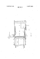
FIG. 2 is a diagrammatic view in elevation of the sidewall blank feeding and heating section and the forming turret of the machine of FIG. 1;
FIG. 3 is a simplified top plan view of the sidewall blank feeding and heating section of FIG. 2;
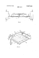
FIG. 4 is an elevational view, partly in cross section, of the transverse heater of FIG. 3; and
FIG. 5 is a simplified perspective view showing the relationship of the three heaters to the sidewall blank being heated.
Referring now to the drawings in detail and to FIG. 1 in particular, the carton forming, filling and sealing machine comprises a forming section 11 and a filling and sealing section 12. The forming section 11 comprises a sidewall blank feeding and heating subsection 13, a bottom blank feeding and heating subsection 14, a forming. subsection 15, and a transfer subsection 16. The filling and sealing section 12 has two parallelendless conveyor systems 17, and each conveyor system comprises a filling subsection 18 occupying five conveyor stations, a defoaming station 19, a score breaking station 20, a top heating station 21, a folding and seal-,
The sidewall blanks 31 manually placed in the sidewall blank magazine 32 are flat, relatively stiff single sheets of paperboard, rectangular in shape, scored to provide five longitudinal panels and a gable-top structure, and coated on both the top and bottom surfaces of each sheet witha thermoplastic material, e.g., polyethylene. The sidewall blanks are successively withdrawn from magazine 32 and advanced through the sidewall blank heating station 33 to the sidewall blank receiving station 34 for turret 35. At the sidewall blank heating station 33, the side margins to be'overlapped and the bottom margin of the sidewall blank are heated to a bonding temperature for the thermoplastic coating.
The turret 35 is journalled on a horizontal axis and carries eight circumferentially spaced apart mandrels 36 extending radially from the axis of turret 35. The cross section of each of mandrels 36 in a plane perpendicular to its longitudinal axis is generally rectangular. Suitable drive mechanism is provided for indexing or effecting intermittent rotation of the turret 35 to move each mandrel from the sidewall blank receiving station 34 through a blank folding station 37; a bottom end closure forming, applying and sealing station 38; a secondary bottom sealing station 39; a stripping station 40; and three successive nonoperating stations 41, 42 and 43.
The tubular carton body having a bottom closure sealed thereto is removed from the mandrel 36 at the stripping station 40 and is transferred to a conveyor pocket 45 of one of the two conveyor systems 17. The product to be packaged is introduced into the opentopped tubular carton in the filling subsection 18. If desired, any foam resulting from the filling operation can be removed at defoaming station 19. The scores for the gable-top structure can be initially folded in the score breaking station 20, resulting in the conventional sixsided top structure. The gable-top ridge panels of the carton are heated in station 21 to a temperature at least as high as the thermal bonding temperature of the thermoplastic coatings on the carton. The heated superstructure is then folded into contact under pressure at the folding and sealing station 22 to effect the bonding of adjacent ridge panels. Secondary sealing station 23 applies pressure to the ridge panels during cooling of the thermoplastic bond. If desired, a data indicia, plant identification orother information can be applied to the bonded ridge panels of the sealed carton at branding station 24. The formed, filled and sealed carton is removed from its conveyor pocket 45 at the transfer station 25 and placed on a delivery conveyor 46.
Referring now to FIG. 2, the turret 35 is intermittently rotated in a clockwise direction, as shown on the drawing, by suitable means, not shown. Chain 51 is driven by turret 35 and in turn drives shaft 52. Shaft 52 intermittently drives sidewall conveyor chains 53.
wardly directed jets of unheated air from air supply tube 59 when the operation of the machine is interrupted, thereby providing cooling for the sidewall blanks in the stack as a protection against damage of the sidewall blanks in the stack by excessive exposure to the hot air from heaters 56, 57, and 58..
A supply magazine cage 32 for the storage of sidewall blanks 31 is formed by opposing side elements 61 and opposing side elements 61 and 62 and opposing end elements 63 and 64 to engage marginal portions of the bottom surface of the lowermost sidewall blanks 31 to support the stack of a plurality of sidewall blanks in cage 32. The magazine cage 32 is supported above the upper run of conveyor chains 53. The blank transfer means for successively withdrawing individual blanks 31 from the magazine cage 32 and depositing the withdrawn blanks on the upper run of conveyor chains 53 comprises vacuum cups 67 and the associated mecha nism. Vacuum cups 67 are mounted between conveyor chains 53. Cups 67 are reciprocated vertically through openings 68 in plate 69 to engage the bottom surface of central portions of the lowermost sidewall blank and to remove the lowermost sidewall blank 31 from the stack of sidewall blanks in cage 32 by causing the lowermost sidewall blank to move inwardly and slip past ledges 66. Vacuum cups 67 are connected to a suitable vacuum source 71. In their lower position, cups 67 are below the upper surface of plate 69 and the upper edges of conveyor chains 53 so as not to interfere with the lateral movement of a blank by conveyor chains 53.
Each vacuum cup 67 is supported by a sleeve 72 attached to a connecting bar 73 by an arm 74. The connecting bar 73 is attached to the upper end of shaft 75. Shaft 75 is reciprocated vertically by linkage 76 and drive cam 77 during the dwell portion of each index cycle for conveyor 54.
Referring now to FIGS. 25, the edge heater 56 comprises an electrical heater 78 having an air passage therethrough, conduit means 79 connecting the air inlet of heater 78 to a source of air under pressure, not shown, and a U shaped tube having an upper leg 80 and -a lower leg 81. One end of leg 80 is connected to the hot air outlet of heater 78'and the remote end of leg 81 is closed. Leg 811 is provided with a series of orifices 82 spaced along the length of the lower surface thereof in a pattern which overlies the top surface of the left side (as viewed from magazine 32) margin of blank 31 in heating station 33 to direct jets of heated air against the top surface of said left margin to heat the thermoplastic coating thereon to a suitable bonding temperature. The lower surface of leg 81 is parallel to the left side edge of blank 31 and spaced therefrom, and preferably directly overlies the margin to be heated so that the hot air jets strike the blank 31 at angles of approximately 90, although the angle of impingement of the jets on the blank can vary from 90. The length of the pattern of orifices 82 is preferably coextensive with the length of the side edge of blank 31.
The edge heater 57 comprises an electrical heater 83 having an air passage therethrough, conduit means 84 connected to a suitable source of air underpressure, and an L shaped conduit comprising leg 85 and 86. One end of conduit 85 is connected to the heated air outlet of heater 83 and the remote end of leg 86 is closed. Leg 86 is provided with a series of orifices 87 in the upper surface thereof in a pattern which is at least substantially coextensive'with the length of the right side edge of blank 31 and which preferably is directly below the right side margin of blank 31 in the heating station 33, so that the jets of heated air strike the lower surface of the right side margin to heat the thermoplastic coating thereon to a suitable bonding temperature. The upper surface of leg 86 is at least substantially parallel to and spaced from the right side edge of blank 31. As shown in FIG. 5 the inlet to the leg 81 is at the top edge of the blank 31 while the inlet to leg 86 is at the bottom edge of blank 31. Thus the initial orifice ofleg 81 is adjacent the top margin of blank 31 while the initial orifice of leg 86 is adjacent the bottom margin of blank 31. This opposite positioning of the two side heaters compensates for any drop in the temperature of the heated air occurring along the length of legs 81 and 86 and provides a substantially uniform temperature in the bonding area when the heated margins are joined.
In the presently preferred embodiment illustrated in the drawings, the transverse heater 58 comprises first and second electrical heaters 88 and 89 having the hot air outlets thereof connected to conduits 90 and 91, respectively. The remote ends of conduits 90 and 91 are joined together by partition plate 92 to provide two separate plenum chambers. The air inlets of heaters 88 and 89 are connected to suitable sources of air under pressure by conduits 93 and 94, respectively. Conduits 90 and 91 are provided with a series of orifices 95 in the lower surface thereof in a pattern which is at least substantially coextensive with the width of the bottom edge of blank 31, and which preferably directly overlies the top surface of the bottom margin of the blank in the heating station 33. The utilization of two heaters 88 and 89 and the partition 92 at approximately the midpoint of the width of the blank 31 minimizes the variation in the temperature to which the various portions of the bottom margin are heated. The conduits 90 and 91 are positioned with the lower surface thereof at least substantially parallel to and spaced from the bottom edge of blank 31 inthe heating station 33.
A valve means 96 is positioned between conduit 97 and air tube 59. Conduit 97 is connected to a suitable means of at least substantially unheated air under pressure. Conduit 59 is provided with a series of orifices in the lower surface thereof to direct jets of cool air downwardly to form an air curtain between magazine 32 and transverse heater 58. Valve 96, which is normally closed, is actuated to the open position by suitable control means whenever the machine is energized but conveyor 53 is deactuated. This air curtain protects the blanks 31 in the magazine 32 against excessive temperatures, while avoiding the operational difficulties which would be incurred if heaters 56, S7 and 58 had to be deactuated whenever conveyor 53 became deactuated. With this system the heaters 56, 57 and 58 continue normal operation and only the blank 31 in the heating station 33 is damaged. The damaged blank can be readily removed by the operator before restarting conveyor 53.
While the invention has been illustrated with rectangular blanks for gable-top cartons, the invention can be utilized with blanks of other generally rectangular configuration, for example the approximately trapezoidal blanks for frustoconical cartons. In this latter case, heaters 56 and 57 would remain parallel to the edges to be heated but would not be parallel to each other, and conduits 90 and 91 could have arcuate configuration conforming to the shape of the bottom edge of the blank.
Reasonable variations and modifications are possible within the scope of the foregoing disclosure, the drawings, and the appended claims to the invention.
Thatwhich is claimed is:
1. In a machine for forming a tubular carton from a generally rectangular flat sidewall blank having thermoplastic coating on the upper and lower surfaces thereof and having first and second side margins and top and bottom margins, wherein the sidewall blanks are individually removed from a sidewall blank magazine and conveyed through a heating station to a forming mandrel, the heated sidewall blank is wrapped around the forming mandrel and the overlapping first and second side margins are bonded together, the improvement comprising a first conduit means positioned in said heating station at least generally parallel to and spaced upwardly from the location which would be occupied by the upper surface of the first side margin of one of said blanks in said heating station, said first conduit having orifices therein spaced along the length thereof and directed at the location which would be occupied by said upper surface of said first side margin of the blank in said heating station, a second conduit means positioned in said heating station at least generally parallel to and spaced downwardly from the loca-.
tion which would be occupied by the lower surface of the second side margin of the blank in said heating station, said second conduit means having orifices therein spaced along the length thereof and directed at the location which would be occupied by the lower surface of said second side margin of the blank in said heating station, and means for supplying a hot gas to said first and second conduit means.
2. Apparatus in accordance with claim 1 further comprising third conduit means positioned in said heating station at least generally parallel to and spaced from the location which would be occupied by the upper surface of the bottom margin of the blank in said heating station, said third conduit means having orifices therein spaced along the length thereof and. directed at the location which would be occupied by the upper surface of said bottom margin of the blank in said heating station, and means for supplying hot gas to said third conduit means.
3. Apparatus in accordance with claim 2 wherein the means for conveying the individual blanks through said heating station is periodically actuated to index a blank into position with respect to said first, second and third conduit means.
4. Apparatus in accordance with claim 3 wherein the initial orifice in one of said first and second conduit means isadjacent the location which would be occupied by the top margin of the blank in said heating station and the initial orifice of the other of said first and second conduits is adjacent the location which would be occupied by the bottom margin of the blank in said heating station.
5. Apparatus in accordance with claim 4 wherein said third conduit means has a partition therein at about the midpoint of the width of the space which would be occupied by the blank in the heating station to form separate plenum chambers, and wherein said means for sup plying hot gas to said third conduit means comprises means for supplying hot gas to each of said plenum chambers at locations remote from said partition.
6. Apparatus in accordance with claim 5 further comprising a fourth conduit means positioned between said magazine and said heating station, said fourth conduit means having a series of orifices therein spaced along the length thereof to form an air curtain between said magazine and said heating station, and means for providing cool gas to said fourth conduit means.
7. Apparatus in accordance with claim 6 wherein said means for providing cool gas to said fourth conduit means is actuated only when the machine is actuated but said means for conveying is deactuated.
8. Apparatus in accordance with claim 1 wherein the I initial orifice in one of said first and second conduit means is adjacent the location which would be occupied by the top margin of the blank in said heating station and the initial orifice of the other of said first and second conduits is adjacent the location which would be occupied by the bottom margin of the blank in said heating station.
9. Apparatus in accordance with claim 2 wherein said third conduit means has a partition therein at about the midpoint of the width of the space which would be occupied by the blank in the heating station to form separate plenum chambers, and wherein said means for supplying hot gas to said third conduit means comprises means for supplying hot gas to each of said plenum chambers at locations remote from said partition.
10. Apparatus in accordance with claim 1 further comprising a fourth conduit means positioned between said magazine and said heating station, said fourth conduit means having a series of orifices therein spaced along the length thereof to form an air curtain between said magazine and said heating station, and means for providing cool gas to said fourth conduit means.
Claims (10)
1. In a machine for forming a tubular carton from a generally rectangular flat sidewall blank having thermoplastic coating on the upper and lower surfaces thereof and having first and second side margins and top and bottom margins, wherein the sidewall blanks are individually removed from a sidewall blank magazine and conveyed through a heating station to a forming mandrel, the heated sidewall blank is wrapped around the forming mandrel and the overlapping first and second side margins are bonded together, the improvement comprising a first conduit means positioned in said heating station at least generally parallel to and spaced upwardly from the location which would be occupied by the upper surface of the first side margin of one of said blanks in said heating station, said first conduit having orifices therein spaced along the length thereof and directed at the location which would be occupied by said upper surface of said first side margin of the blank in said heating station, a second conduit means positioned in said heating station at least generally parallel to and spaced downwardly from the location which would be occupied by the lower surface of the second side margin of the blank in said heating station, said second conduit means having orifices theRein spaced along the length thereof and directed at the location which would be occupied by the lower surface of said second side margin of the blank in said heating station, and means for supplying a hot gas to said first and second conduit means.
2. Apparatus in accordance with claim 1 further comprising third conduit means positioned in said heating station at least generally parallel to and spaced from the location which would be occupied by the upper surface of the bottom margin of the blank in said heating station, said third conduit means having orifices therein spaced along the length thereof and directed at the location which would be occupied by the upper surface of said bottom margin of the blank in said heating station, and means for supplying hot gas to said third conduit means.
3. Apparatus in accordance with claim 2 wherein the means for conveying the individual blanks through said heating station is periodically actuated to index a blank into position with respect to said first, second and third conduit means.
4. Apparatus in accordance with claim 3 wherein the initial orifice in one of said first and second conduit means is adjacent the location which would be occupied by the top margin of the blank in said heating station and the initial orifice of the other of said first and second conduits is adjacent the location which would be occupied by the bottom margin of the blank in said heating station.
5. Apparatus in accordance with claim 4 wherein said third conduit means has a partition therein at about the midpoint of the width of the space which would be occupied by the blank in the heating station to form separate plenum chambers, and wherein said means for supplying hot gas to said third conduit means comprises means for supplying hot gas to each of said plenum chambers at locations remote from said partition.
6. Apparatus in accordance with claim 5 further comprising a fourth conduit means positioned between said magazine and said heating station, said fourth conduit means having a series of orifices therein spaced along the length thereof to form an air curtain between said magazine and said heating station, and means for providing cool gas to said fourth conduit means.
7. Apparatus in accordance with claim 6 wherein said means for providing cool gas to said fourth conduit means is actuated only when the machine is actuated but said means for conveying is deactuated.
8. Apparatus in accordance with claim 1 wherein the initial orifice in one of said first and second conduit means is adjacent the location which would be occupied by the top margin of the blank in said heating station and the initial orifice of the other of said first and second conduits is adjacent the location which would be occupied by the bottom margin of the blank in said heating station.
9. Apparatus in accordance with claim 2 wherein said third conduit means has a partition therein at about the midpoint of the width of the space which would be occupied by the blank in the heating station to form separate plenum chambers, and wherein said means for supplying hot gas to said third conduit means comprises means for supplying hot gas to each of said plenum chambers at locations remote from said partition.
10. Apparatus in accordance with claim 1 further comprising a fourth conduit means positioned between said magazine and said heating station, said fourth conduit means having a series of orifices therein spaced along the length thereof to form an air curtain between said magazine and said heating station, and means for providing cool gas to said fourth conduit means.
Priority Applications (6)
| Application Number | Priority Date | Filing Date | Title |
|---|---|---|---|
| US39503573 US3847540A (en) | 1973-09-07 | 1973-09-07 | Blank heating system for carton forming machine |
| CA208,455A CA1010281A (en) | 1973-09-07 | 1974-09-04 | Blank heating system for carton forming machine |
| DE19747430127U DE7430127U (en) | 1973-09-07 | 1974-09-06 | MACHINE FOR MANUFACTURING TUBULAR BOXES |
| JP10284974A JPS5331062B2 (en) | 1973-09-07 | 1974-09-06 | |
| FR7430370A FR2243078B1 (en) | 1973-09-07 | 1974-09-06 | |
| DE2442858A DE2442858C3 (en) | 1973-09-07 | 1974-09-06 | Machine for forming tubular cardboard boxes |
Applications Claiming Priority (1)
| Application Number | Priority Date | Filing Date | Title |
|---|---|---|---|
| US39503573 US3847540A (en) | 1973-09-07 | 1973-09-07 | Blank heating system for carton forming machine |
Publications (1)
| Publication Number | Publication Date |
|---|---|
| US3847540A true US3847540A (en) | 1974-11-12 |
Family
ID=23561435
Family Applications (1)
| Application Number | Title | Priority Date | Filing Date |
|---|---|---|---|
| US39503573 Expired - Lifetime US3847540A (en) | 1973-09-07 | 1973-09-07 | Blank heating system for carton forming machine |
Country Status (5)
| Country | Link |
|---|---|
| US (1) | US3847540A (en) |
| JP (1) | JPS5331062B2 (en) |
| CA (1) | CA1010281A (en) |
| DE (2) | DE2442858C3 (en) |
| FR (1) | FR2243078B1 (en) |
Cited By (17)
| Publication number | Priority date | Publication date | Assignee | Title |
|---|---|---|---|---|
| US4035926A (en) * | 1976-05-24 | 1977-07-19 | Phillips Petroleum Company | Heating the end of a tubular member |
| US4052152A (en) * | 1976-02-18 | 1977-10-04 | Sun Chemical Corporation | Direct flame drying apparatus |
| US4052154A (en) * | 1976-05-28 | 1977-10-04 | Container Corporation Of America | Apparatus for heat sealing of container bodies |
| US4311458A (en) * | 1979-07-19 | 1982-01-19 | Caratsch Hans Peter | Tunnel furnace for fabricating plate-like flat structures, especially printed circuit boards coated at both sides with a curable material |
| US4317323A (en) * | 1977-11-21 | 1982-03-02 | Phillips Petroleum Company | Apparatus for producing containers |
| US4349400A (en) * | 1977-05-10 | 1982-09-14 | Maryland Cup Corporation | Method for manufacturing two-piece containers from filled thermoplastic sheet material |
| US5188775A (en) * | 1990-09-17 | 1993-02-23 | Owens-Illinois Plastic Products Inc. | Method and apparatus for shrinking a foam sleeve on a taper wall container |
| US5236408A (en) * | 1992-07-21 | 1993-08-17 | International Paper Box Machine Company, Inc. | Method and apparatus for forming carton blanks with hemmed edges |
| US5273513A (en) * | 1988-11-30 | 1993-12-28 | Sprinter System Ab | Automatic setting apparatus in box or carton blank erection machines |
| US5435804A (en) * | 1992-08-28 | 1995-07-25 | Paper Machinery Corporation | Cup making machine |
| US5571224A (en) * | 1994-03-11 | 1996-11-05 | James River Corporation Of Virginia | Preconditioned paperboard containers and method and apparatus for making the same |
| US5584789A (en) * | 1994-09-06 | 1996-12-17 | Sealright Co., Inc. | Method and apparatus for forming non-round containers |
| US5891380A (en) * | 1989-12-28 | 1999-04-06 | Zapata Innovative Closures, Inc. | Tamper evident caps and methods |
| US6134387A (en) * | 1995-05-15 | 2000-10-17 | Toss; Ramon | Process and device for hot gas welding of plastic sheets with electrically heated tubular gas flow conduit |
| US20040151481A1 (en) * | 2001-04-23 | 2004-08-05 | Stefano Cassoli | Apparatus for the heat sealing of thermoplastic packagings or wrappings |
| US20060046916A1 (en) * | 2004-08-24 | 2006-03-02 | Gamache Brian N | Apparatus and method for forming a hemmed edge on carton blanks |
| US11065824B2 (en) * | 2016-08-31 | 2021-07-20 | Sig Technology Ag | Device and method for producing packaging precursors by means of a heating device acting on the edge area of the packaging precursor |
Families Citing this family (3)
| Publication number | Priority date | Publication date | Assignee | Title |
|---|---|---|---|---|
| DE2908396C2 (en) * | 1979-03-03 | 1983-12-15 | Aktiebolaget Akerlund & Rausing, 22101 Lund | Device for activating a flat folding box blank |
| DE3210967C2 (en) * | 1982-03-25 | 1985-07-11 | Manfred 6120 Michelstadt Scholz | Process and device for the production of folding box blanks from PVC film with pre-embossed bending edges |
| TR201910731T4 (en) * | 2013-04-10 | 2019-08-21 | Tetra Laval Holdings & Finance | The method and device that realizes the method for processing packaging laminate |
Citations (3)
| Publication number | Priority date | Publication date | Assignee | Title |
|---|---|---|---|---|
| US1677492A (en) * | 1925-12-26 | 1928-07-17 | Barber Asphalt Co | Apparatus for heating sheet material in preparation for folding |
| US2605091A (en) * | 1948-04-13 | 1952-07-29 | American Can Co | Method and apparatus for treating articles with jets of fluid |
| US3642012A (en) * | 1969-09-03 | 1972-02-15 | American Sterilizer Co | Sterilizing apparatus for continuously sterilizing articles by flames means |
-
1973
- 1973-09-07 US US39503573 patent/US3847540A/en not_active Expired - Lifetime
-
1974
- 1974-09-04 CA CA208,455A patent/CA1010281A/en not_active Expired
- 1974-09-06 DE DE2442858A patent/DE2442858C3/en not_active Expired
- 1974-09-06 FR FR7430370A patent/FR2243078B1/fr not_active Expired
- 1974-09-06 JP JP10284974A patent/JPS5331062B2/ja not_active Expired
- 1974-09-06 DE DE19747430127U patent/DE7430127U/en not_active Expired
Patent Citations (3)
| Publication number | Priority date | Publication date | Assignee | Title |
|---|---|---|---|---|
| US1677492A (en) * | 1925-12-26 | 1928-07-17 | Barber Asphalt Co | Apparatus for heating sheet material in preparation for folding |
| US2605091A (en) * | 1948-04-13 | 1952-07-29 | American Can Co | Method and apparatus for treating articles with jets of fluid |
| US3642012A (en) * | 1969-09-03 | 1972-02-15 | American Sterilizer Co | Sterilizing apparatus for continuously sterilizing articles by flames means |
Cited By (18)
| Publication number | Priority date | Publication date | Assignee | Title |
|---|---|---|---|---|
| US4052152A (en) * | 1976-02-18 | 1977-10-04 | Sun Chemical Corporation | Direct flame drying apparatus |
| US4035926A (en) * | 1976-05-24 | 1977-07-19 | Phillips Petroleum Company | Heating the end of a tubular member |
| US4052154A (en) * | 1976-05-28 | 1977-10-04 | Container Corporation Of America | Apparatus for heat sealing of container bodies |
| US4349400A (en) * | 1977-05-10 | 1982-09-14 | Maryland Cup Corporation | Method for manufacturing two-piece containers from filled thermoplastic sheet material |
| US4317323A (en) * | 1977-11-21 | 1982-03-02 | Phillips Petroleum Company | Apparatus for producing containers |
| US4311458A (en) * | 1979-07-19 | 1982-01-19 | Caratsch Hans Peter | Tunnel furnace for fabricating plate-like flat structures, especially printed circuit boards coated at both sides with a curable material |
| US5273513A (en) * | 1988-11-30 | 1993-12-28 | Sprinter System Ab | Automatic setting apparatus in box or carton blank erection machines |
| US5891380A (en) * | 1989-12-28 | 1999-04-06 | Zapata Innovative Closures, Inc. | Tamper evident caps and methods |
| US5188775A (en) * | 1990-09-17 | 1993-02-23 | Owens-Illinois Plastic Products Inc. | Method and apparatus for shrinking a foam sleeve on a taper wall container |
| US5236408A (en) * | 1992-07-21 | 1993-08-17 | International Paper Box Machine Company, Inc. | Method and apparatus for forming carton blanks with hemmed edges |
| US5435804A (en) * | 1992-08-28 | 1995-07-25 | Paper Machinery Corporation | Cup making machine |
| US5571224A (en) * | 1994-03-11 | 1996-11-05 | James River Corporation Of Virginia | Preconditioned paperboard containers and method and apparatus for making the same |
| US5584789A (en) * | 1994-09-06 | 1996-12-17 | Sealright Co., Inc. | Method and apparatus for forming non-round containers |
| US6134387A (en) * | 1995-05-15 | 2000-10-17 | Toss; Ramon | Process and device for hot gas welding of plastic sheets with electrically heated tubular gas flow conduit |
| US20040151481A1 (en) * | 2001-04-23 | 2004-08-05 | Stefano Cassoli | Apparatus for the heat sealing of thermoplastic packagings or wrappings |
| US20060046916A1 (en) * | 2004-08-24 | 2006-03-02 | Gamache Brian N | Apparatus and method for forming a hemmed edge on carton blanks |
| US7137941B2 (en) * | 2004-08-24 | 2006-11-21 | Folder-Gluer Technical Services Group, Inc. | Apparatus and method for forming a hemmed edge on carton blanks |
| US11065824B2 (en) * | 2016-08-31 | 2021-07-20 | Sig Technology Ag | Device and method for producing packaging precursors by means of a heating device acting on the edge area of the packaging precursor |
Also Published As
| Publication number | Publication date |
|---|---|
| DE2442858B2 (en) | 1977-11-24 |
| DE7430127U (en) | 1979-06-13 |
| JPS5072776A (en) | 1975-06-16 |
| CA1010281A (en) | 1977-05-17 |
| JPS5331062B2 (en) | 1978-08-31 |
| FR2243078A1 (en) | 1975-04-04 |
| DE2442858A1 (en) | 1975-03-27 |
| DE2442858C3 (en) | 1978-11-30 |
| FR2243078B1 (en) | 1977-07-08 |
Similar Documents
| Publication | Publication Date | Title |
|---|---|---|
| US3825408A (en) | Hot air heater for carton sealing machine | |
| US3120089A (en) | Machine for forming plastic coated paperboard containers | |
| US3239995A (en) | Machine for forming, filling, closing and sealing plastic coated paperboard containers | |
| US3207049A (en) | Machine for forming plastic coated paperboard containers and erecting and deliveringmeans therefor | |
| US3789746A (en) | Packaging machine | |
| EP0079561B1 (en) | Transfer means | |
| US3153991A (en) | Apparatus for the manufacture of composite carton blanks | |
| US3303761A (en) | Machine for forming, filling, closing and sealing plastic coated paperboard containers | |
| GB1454464A (en) | Manufacture of packaging containers | |
| US5269741A (en) | Process and machine for erecting a folding carton | |
| US3660962A (en) | Shrink film package, and apparatus and method for making same | |
| US4035926A (en) | Heating the end of a tubular member | |
| US4299590A (en) | Cartoning machine | |
| US3392458A (en) | Selective heater for container closures | |
| RU2321495C2 (en) | Container forming system, especially, containers for food products | |
| US2973608A (en) | High-speed system for feeding and sealing cartons | |
| EP0832731B1 (en) | Heating device for heat-sealing bottom portions of containers | |
| EP0249264B1 (en) | A mandrel for forming a bottom in a packaging container | |
| US3860108A (en) | Double ratchet conveyor drive mechanism | |
| US3153374A (en) | Carton forming machine | |
| US2785610A (en) | Apparatus for assembling, impregnating and delivering containers of paper, cardboardor the like carton forming material | |
| US3533332A (en) | Method and apparatus for forming a container | |
| US3709114A (en) | Container forming machine | |
| US3166994A (en) | Rotating carton tucker apparatus | |
| JPH0592109U (en) | Equipment for transporting goods in the form of packaging containers |
Legal Events
| Date | Code | Title | Description |
|---|---|---|---|
| AS | Assignment |
Owner name: SEALRIGHT CO., INC. A DE CORP. Free format text: ASSIGNMENT OF ASSIGNORS INTEREST.;ASSIGNOR:PHILLIPS PETROLEUM COMPANY A DE CORP.;REEL/FRAME:004099/0393 Effective date: 19821116 |