US3816A - I i john g - Google Patents
I i john g Download PDFInfo
- Publication number
- US3816A US3816A US3816DA US3816A US 3816 A US3816 A US 3816A US 3816D A US3816D A US 3816DA US 3816 A US3816 A US 3816A
- Authority
- US
- United States
- Prior art keywords
- tide
- wheel
- water
- race
- dam
- Prior art date
- Legal status (The legal status is an assumption and is not a legal conclusion. Google has not performed a legal analysis and makes no representation as to the accuracy of the status listed.)
- Expired - Lifetime
Links
- XLYOFNOQVPJJNP-UHFFFAOYSA-N water Substances O XLYOFNOQVPJJNP-UHFFFAOYSA-N 0.000 description 40
- 230000000694 effects Effects 0.000 description 4
- 230000001105 regulatory Effects 0.000 description 4
- 230000000630 rising Effects 0.000 description 4
- 239000002023 wood Substances 0.000 description 4
- 210000003128 Head Anatomy 0.000 description 2
- 241001237731 Microtia elva Species 0.000 description 2
- OKTJSMMVPCPJKN-UHFFFAOYSA-N carbon Chemical compound [C] OKTJSMMVPCPJKN-UHFFFAOYSA-N 0.000 description 2
- 238000010276 construction Methods 0.000 description 2
- 230000000875 corresponding Effects 0.000 description 2
- 238000005188 flotation Methods 0.000 description 2
- 239000002184 metal Substances 0.000 description 2
- 239000004576 sand Substances 0.000 description 2
- 239000007787 solid Substances 0.000 description 2
Images

Classifications
-
- F—MECHANICAL ENGINEERING; LIGHTING; HEATING; WEAPONS; BLASTING
- F03—MACHINES OR ENGINES FOR LIQUIDS; WIND, SPRING, OR WEIGHT MOTORS; PRODUCING MECHANICAL POWER OR A REACTIVE PROPULSIVE THRUST, NOT OTHERWISE PROVIDED FOR
- F03B—MACHINES OR ENGINES FOR LIQUIDS
- F03B13/00—Adaptations of machines or engines for special use; Combinations of machines or engines with driving or driven apparatus; Power stations or aggregates
- F03B13/12—Adaptations of machines or engines for special use; Combinations of machines or engines with driving or driven apparatus; Power stations or aggregates characterised by using wave or tide energy
- F03B13/26—Adaptations of machines or engines for special use; Combinations of machines or engines with driving or driven apparatus; Power stations or aggregates characterised by using wave or tide energy using tide energy
- F03B13/264—Adaptations of machines or engines for special use; Combinations of machines or engines with driving or driven apparatus; Power stations or aggregates characterised by using wave or tide energy using tide energy using the horizontal flow of water resulting from tide movement
-
- Y—GENERAL TAGGING OF NEW TECHNOLOGICAL DEVELOPMENTS; GENERAL TAGGING OF CROSS-SECTIONAL TECHNOLOGIES SPANNING OVER SEVERAL SECTIONS OF THE IPC; TECHNICAL SUBJECTS COVERED BY FORMER USPC CROSS-REFERENCE ART COLLECTIONS [XRACs] AND DIGESTS
- Y02—TECHNOLOGIES OR APPLICATIONS FOR MITIGATION OR ADAPTATION AGAINST CLIMATE CHANGE
- Y02E—REDUCTION OF GREENHOUSE GAS [GHG] EMISSIONS, RELATED TO ENERGY GENERATION, TRANSMISSION OR DISTRIBUTION
- Y02E10/00—Energy generation through renewable energy sources
- Y02E10/20—Hydro energy
-
- Y—GENERAL TAGGING OF NEW TECHNOLOGICAL DEVELOPMENTS; GENERAL TAGGING OF CROSS-SECTIONAL TECHNOLOGIES SPANNING OVER SEVERAL SECTIONS OF THE IPC; TECHNICAL SUBJECTS COVERED BY FORMER USPC CROSS-REFERENCE ART COLLECTIONS [XRACs] AND DIGESTS
- Y02—TECHNOLOGIES OR APPLICATIONS FOR MITIGATION OR ADAPTATION AGAINST CLIMATE CHANGE
- Y02E—REDUCTION OF GREENHOUSE GAS [GHG] EMISSIONS, RELATED TO ENERGY GENERATION, TRANSMISSION OR DISTRIBUTION
- Y02E10/00—Energy generation through renewable energy sources
- Y02E10/30—Energy from the sea, e.g. using wave energy or salinity gradient
Definitions
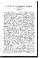
- Fig. 2 is a sectional elevation, lengthwise in the line A, B, Fig. ⁇ l;
- Fig. 3 is a cross sectional elevation of the parts, at the end A, of Figs. ⁇ l, and 2, seen, as cut through the wheel;
- Fig. 4 is a cross sectional elevation of the parts at the end B,
- Fig. 5 is a plan of the wheel race, water ⁇ or tide gate, and parts near the foundationof the dam walls, and wheel race, and below the line ⁇ 06,1 m, Fig. 2, and the same letters numbers and other marks of reference, apply to the like parts, in all the several figures. ⁇ y
- C is the outer dam wall, next the tide, on open space of tide water T; D, is the inner dam wall, next the mill pond or inclosed space M; these walls ⁇ C, and D, together form the wheel race Fn and as will be seen hereafter", may be made of any length, to
- the walls are to be built so as to forma pit, or opening F, from the surface, down to the foundation, but constructed with openings in the base, neXtt-he race at a, seethe Figs. 2, 3, and "4f, to admit the rise and fall of the tide, in the pits F, for the purpose of floating the caissons G, G', at the level of the tide water, these may be made of wood, ⁇ or metal, ⁇ or
- l, 2, ,and 4 carry a head block l1, in which two large pulleys 7, and ⁇ two small pulleys S, receive chains 6, 6, secured one end by an eye to the standards b, b', and passing over the pulleys 7, and 8 terminate, each, in an eye on a box z', containing a mass of heavy matter, sufficient to counterpoise the caissons and wheel, andv ratchets andpawls, and mounted in standards g, on the race walls C, and D.
- the single tide gate I is shown shut, against the outer dam wall and forcing the water from the pond side M, of the dam wall D, to pass out, as the tide falls, in the directionof the arrows 13, the inner current gate L is shown as closed, to prevent the water in the pond, passing by that end of the inner dam,fand will remain shut, by the internal water, so long as that in the pond M, is higher, than the external, or falling ⁇ tide water, at T, and the outer current gate K, is shown as open, to pass the water fro-m the race, to the river, or ocean, on the side T, of the dam wall C.
- tide mills have been pro- ⁇ posed, or made, with four ates, to run the water alike, on flood and eb, and requiring manual attendance, to open andshut them, at the'turn of the tide; but no tide mills have, to my knowledge, been proposed, or made, with three self acting gates, and longitudinal dam walls, forming the race, in
Description
JOHN G. Ross, OF NEW YORK, N. Y.
Trim-WHEEL.
Specification of Letters Patent 1\l`o.V 3,1816, dated November 9, 18414.
To all whom t may concern y Be it known that I, JOHN GERARD Boss, of the city, county, and State of New York,
`model-maker and machinist, have invented and made certain new and useful improve-` ments in `the mechanical arrangement,` application, andcombination of the parts` em-` ployed in what is technically known as the tide-mill, the intent and effect of such improvements being that such mills shall beable to work with less loss of time aiidz be more equally and continuously effective than by any arrangement now in use to my ofthe mill-pond shall always run one way:` in the race, whether the tide be rising or falling, and the wheel or wheels are made to rise and fall ,with the water so that no interruption of the power occurs except for a short time atthe high and lowV water `of each tide; these improvements designate collectively v`as, Rosss plemaian or constant tide-mill, and for the same I seek Letters Patent of the United States; and further know'ye that the said` improve ments and the mode of constructing, arranging, applying, and combining the same are fully and substantially set forth and shown in the following description and 1n the drawingsannexed to and making a part of this specification, wherein- Figure 1, is a plan of all the parts in place for use; Fig. 2, is a sectional elevation, lengthwise in the line A, B, Fig. `l; Fig. 3, is a cross sectional elevation of the parts, at the end A, of Figs.` l, and 2, seen, as cut through the wheel; Fig. 4, isa cross sectional elevation of the parts at the end B,
of Figs. l, and 2, seenlikewise, as if cut through the wheel; Fig. 5, is a plan of the wheel race, water `or tide gate, and parts near the foundationof the dam walls, and wheel race, and below the line `06,1 m, Fig. 2, and the same letters numbers and other marks of reference, apply to the like parts, in all the several figures.` y
C, is the outer dam wall, next the tide, on open space of tide water T; D, is the inner dam wall, next the mill pond or inclosed space M; these walls` C, and D, together form the wheel race Fn and as will be seen hereafter", may be made of any length, to
`inclose a space as aimill pond, and may work any number of wheels, that the length will conveniently receive: In each of these walls,4
on each side Vthe wheel race, abreast of or at the side of each wheel, the walls are to be built so as to forma pit, or opening F, from the surface, down to the foundation, but constructed with openings in the base, neXtt-he race at a, seethe Figs. 2, 3, and "4f, to admit the rise and fall of the tide, in the pits F, for the purpose of floating the caissons G, G', at the level of the tide water, these may be made of wood, `or metal, `or
both, of a proper size to float, and thereby maintain a uniform height, above the `water b, o', these are secured in anyconvenient way on the caissons Gr, G, and are tted with journal boxes 1, 1, at a proper or proportional height, to receive the shaft o, of the main tide wheel H, and a curved opening at 4, shown by dotted lines in Fig. 2, as
cut into the inner pit walls, allows the shaft c, to rise and fall with the tide, in the proper line of motion: On each outer end of the shaft c, is a spur wheel d, or elf, these respectively gear into driving wheels e, e', on the ends of a shaft f, see Figs. l, 2, and 3` which is mounted on journal boxes 2, 2, on standards g, g, securely fitted on the solid walls of the dam; Two radius bars 7i, h', are connected by boXes, straps, gibs, and keys 3, 8, to the shafts c, and f, and maintain the proper relative positions between the centers of the shafts c, and f, and wheels H, CZ, and e,these bars 7L, 7i', may be best made, with right and left handed screws in the ends, taking into similar nuts, in the stocks to which` the boxes and straps are fitted, but any other convenient means may be used, that will maintain the properadjustments of the gearing and Working parts.
To secure the proper position of the caissons ,in the centers of the standards or` frames G, G', at each period of the tide, two cir-` cular grooves 5, 5, shown in Fig. l, in place, and by dotted lines in Fig. 2, as` made in the outer side of the pit wall are fitted to receive studs o, or blocks, carrying rollers on the corresponding parts of the caissons, see the detached Fig. 6, where these are shown, sectionally, in place in the pit and wall, the grooves 5, must be 'segments of circles, whose common center may be `found by the intersection of tworectangular lines, from the bisection of straight liiies,-to,` and from, the upper and lower halves of the line of motion, in the caisson. Two standard posts 10, Figs. l, 2, ,and 4,- carry a head block l1, in which two large pulleys 7, and` two small pulleys S, receive chains 6, 6, secured one end by an eye to the standards b, b', and passing over the pulleys 7, and 8 terminate, each, in an eye on a box z', containing a mass of heavy matter, sufficient to counterpoise the caissons and wheel, andv ratchets andpawls, and mounted in standards g, on the race walls C, and D.
The method of giving a current in the samel direction on both the flood and ebb vtide is now to be described. Thesingle tide gate I, Fig. 1, is shown, in this ligure, as`
hung to a competent support in the bank or wall at A, Fig. 1, and closed against the inner dam wall D, admitting the current of the rising, or flood tide, from the tide side T, of the dam wall C, to run through the'race 'E, and carry the wheel H, in the direction shown by the arrows 12; the outer current gate K, is shown, shut, from the outer dam wall C, to a shutting jamb fitted to receive vit in the bank or wall at B, Fig. 1, where `it is kept, by the pressure, caused by the external, or tide water, at T, being higher than that in the mill pond at M, the inner current gate L, being open, to pass the water from the race to the pond M, so that the current, running through the race E, carries the wheel II, as shown by the arrows 12, Fig. 1, and fills the pond M, supplying a water power to run out, when the external tide falls; in Fig. 5, the single tide gate I, is shown shut, against the outer dam wall and forcing the water from the pond side M, of the dam wall D, to pass out, as the tide falls, in the directionof the arrows 13, the inner current gate L is shown as closed, to prevent the water in the pond, passing by that end of the inner dam,fand will remain shut, by the internal water, so long as that in the pond M, is higher, than the external, or falling` tide water, at T, and the outer current gate K, is shown as open, to pass the water fro-m the race, to the river, or ocean, on the side T, of the dam wall C.
In fitting the caissons, Ido not mean to confine, or limit myself to the mode shown,
of balancing them and the wheel and equip- 4ment-s by chains and weights,butIintendto use any other convenient mechanical means,
-for suchV purposes, that maybe substantially the same, in practice and effect, and if when new and dry, the caissons haveV more power of flotation than is required, a small cock may befitted, to admit so much water, as is needful to load the caissons to the required depth; and when, by any cause, the caissons have too much water in them, or become leaky, a small pump may be fitted into either of them, and be attached, in any convenient way, to the main shaft, and worked-so as to keep any such leakage pumped out; and as before premised I do not intend to confine, or limit myself, to the construction of dams, whose length shall be only competent to receive one wheel, with its equipments, but lI intend to make the double dam walls, Vand mill race as long, as the localities of situation will allow, and work anyjnumber of wheels, that the dam walls will receive,plac ing the tide gate at one end, and the current gates at the other end of the dams, whatever their length may be.Y It will be seen, that with any number of wheels, thus fitted, no interruption will take place in the work, eX- cept at the dead low water, or high water of each tide, for the instant the water, on
either side the dam, is higher than on *the opposite side the`V tide gate I, will go over to, and close on, thelowest side, and the like y eect` will takeplace with the current gate, o-n that side, the other current gate opening, to pass the water, so that the operations of the tide, alone, will change the gates, and set the wheel, or wheels, in work; and it will be seen, that in cases, where the wheel race shall be over about twelve feet wide, it mayV be proper to make the tide and current gates in two parts, which may be done, in any convenient and effective. manner, and the pro-` portions, between the width and height of the gates, must be regulated by the proportion existing, between the width of race chosen, and the rise and fall of the tide, in the given locality. It may be proper, to protect the -tide and current gates from wrecks, or drift wood, on the tide side of the dam, but many well known modes can, be chosen for doing this, that it is not ,needful to describe herein.
I am aware, that tide mills have been pro-` posed, or made, with four ates, to run the water alike, on flood and eb, and requiring manual attendance, to open andshut them, at the'turn of the tide; but no tide mills have, to my knowledge, been proposed, or made, with three self acting gates, and longitudinal dam walls, forming the race, in
combination with means to float the wheel,
or wheels, and maintain an equality Yof power, during the flood and ebb; and although the means described, vor Vparts of these described, `for regulating the wheel,
Vmay have been used before, they have not been used, collectively, in tide races, in the.
manner proposed herein, therefore I limitl my claim as follows: Y
I claim as new, and of my own invention, and desire to secure by Letters Patent- 1. The mode described of fitting the tide gate I, at one end of a race way, formedV by 3. I claim the combination of the described Inode of tt'ng the gates, and wheel, or 15 wheels, and making them act together, in the manner described herein.` n
` In witness whereof, I have hereunto set my hand, in the city Vof ANew York, this twentieth day of June, inthe year one thou- 20 sand eight hundred and forty-four.
JOHN GERARD `Ross.
Witnesses:` g
W. SERRELL, t i EDWARD W. SERRELL.
[n s] i
Publications (1)
| Publication Number | Publication Date |
|---|---|
| US3816A true US3816A (en) | 1844-11-09 |
Family
ID=2064117
Family Applications (1)
| Application Number | Title | Priority Date | Filing Date |
|---|---|---|---|
| US3816D Expired - Lifetime US3816A (en) | I i john g |
Country Status (1)
| Country | Link |
|---|---|
| US (1) | US3816A (en) |
Cited By (7)
| Publication number | Priority date | Publication date | Assignee | Title |
|---|---|---|---|---|
| US3807890A (en) * | 1972-10-12 | 1974-04-30 | O Wright | Water power apparatus |
| US4001596A (en) * | 1974-10-03 | 1977-01-04 | Kurtzbein Earl D | Wave and current operated power generating device |
| US5430332A (en) * | 1994-02-28 | 1995-07-04 | Dunn, Jr.; E. D. | Movable and adjustable dam |
| WO2008092178A2 (en) * | 2007-01-30 | 2008-08-07 | Hermann Riegerbauer | Hydraulic power plant comprising a running wheel, sliding block, and flotsam screen |
| ITPD20090190A1 (en) * | 2009-07-08 | 2011-01-09 | Giovanni Pieri | CONVOGULATION DEVICE FOR THE WATER OF A RIVER FOR THE INCREASE OF THE POWER THAT CAN BE EXPENSED TO THE CAPTURE SECTION OF A TURBINE |
| WO2012139113A1 (en) * | 2011-04-08 | 2012-10-11 | Griffin Holdings, Llc | Hydraulic energy converter |
| US20140353972A1 (en) * | 2013-05-29 | 2014-12-04 | Hangzhou Lhd Institute Of New Energy, Llc | Water Flow Regulating Device And Ocean Power Generating Device Using The Same |
-
0
- US US3816D patent/US3816A/en not_active Expired - Lifetime
Cited By (9)
| Publication number | Priority date | Publication date | Assignee | Title |
|---|---|---|---|---|
| US3807890A (en) * | 1972-10-12 | 1974-04-30 | O Wright | Water power apparatus |
| US4001596A (en) * | 1974-10-03 | 1977-01-04 | Kurtzbein Earl D | Wave and current operated power generating device |
| US5430332A (en) * | 1994-02-28 | 1995-07-04 | Dunn, Jr.; E. D. | Movable and adjustable dam |
| WO2008092178A2 (en) * | 2007-01-30 | 2008-08-07 | Hermann Riegerbauer | Hydraulic power plant comprising a running wheel, sliding block, and flotsam screen |
| WO2008092178A3 (en) * | 2007-01-30 | 2008-10-30 | Hermann Riegerbauer | Hydraulic power plant comprising a running wheel, sliding block, and flotsam screen |
| ITPD20090190A1 (en) * | 2009-07-08 | 2011-01-09 | Giovanni Pieri | CONVOGULATION DEVICE FOR THE WATER OF A RIVER FOR THE INCREASE OF THE POWER THAT CAN BE EXPENSED TO THE CAPTURE SECTION OF A TURBINE |
| WO2012139113A1 (en) * | 2011-04-08 | 2012-10-11 | Griffin Holdings, Llc | Hydraulic energy converter |
| US20140353972A1 (en) * | 2013-05-29 | 2014-12-04 | Hangzhou Lhd Institute Of New Energy, Llc | Water Flow Regulating Device And Ocean Power Generating Device Using The Same |
| US9206573B2 (en) * | 2013-05-29 | 2015-12-08 | Hangzhou Lhd Institute Of New Energy, Llc | Water flow regulating device and ocean power generating device using the same |
Similar Documents
| Publication | Publication Date | Title |
|---|---|---|
| US4317330A (en) | Water turbine generator system | |
| US3816A (en) | I i john g | |
| US2335327A (en) | Wicket | |
| US85598A (en) | Samuel lewi s | |
| US6132A (en) | Apparatus for current-wheels | |
| US2098876A (en) | Hydraulic power plant | |
| US1081867A (en) | Current-motor. | |
| US78488A (en) | Albebt b | |
| US30591A (en) | John g | |
| US1099085A (en) | Tide and wave motor. | |
| US1726405A (en) | Current motor | |
| US282400A (en) | Kcmsty stoney | |
| US1208648A (en) | Floating ice-sawing machine. | |
| US954257A (en) | Flashboard. | |
| US596335A (en) | Tide-motor | |
| US344879A (en) | Canal-lock | |
| US1296242A (en) | Propeller. | |
| US3129A (en) | Improvement in s | |
| US526082A (en) | Wave-motor | |
| US68833A (en) | Martin bishop | |
| US38887A (en) | Improvement in water-wheels | |
| US802767A (en) | Current-motor. | |
| US794988A (en) | Water-power. | |
| US19346A (en) | Pbopelung canal-boats | |
| US907437A (en) | Movable barrage having rotary sluice-pontoons. |