US3803662A - Carpet adhesive spreader - Google Patents
Carpet adhesive spreader Download PDFInfo
- Publication number
- US3803662A US3803662A US00313009A US31300972A US3803662A US 3803662 A US3803662 A US 3803662A US 00313009 A US00313009 A US 00313009A US 31300972 A US31300972 A US 31300972A US 3803662 A US3803662 A US 3803662A
- Authority
- US
- United States
- Prior art keywords
- spreader
- frame member
- spreading
- handle
- respect
- Prior art date
- Legal status (The legal status is an assumption and is not a legal conclusion. Google has not performed a legal analysis and makes no representation as to the accuracy of the status listed.)
- Expired - Lifetime
Links
Images

Classifications
-
- A—HUMAN NECESSITIES
- A47—FURNITURE; DOMESTIC ARTICLES OR APPLIANCES; COFFEE MILLS; SPICE MILLS; SUCTION CLEANERS IN GENERAL
- A47G—HOUSEHOLD OR TABLE EQUIPMENT
- A47G27/00—Floor fabrics; Fastenings therefor
- A47G27/04—Carpet fasteners; Carpet-expanding devices ; Laying carpeting; Tools therefor
- A47G27/0487—Tools for laying carpeting
-
- B—PERFORMING OPERATIONS; TRANSPORTING
- B05—SPRAYING OR ATOMISING IN GENERAL; APPLYING FLUENT MATERIALS TO SURFACES, IN GENERAL
- B05C—APPARATUS FOR APPLYING FLUENT MATERIALS TO SURFACES, IN GENERAL
- B05C17/00—Hand tools or apparatus using hand held tools, for applying liquids or other fluent materials to, for spreading applied liquids or other fluent materials on, or for partially removing applied liquids or other fluent materials from, surfaces
- B05C17/10—Hand tools for removing partially or for spreading or redistributing applied liquids or other fluent materials, e.g. colour touchers
-
- E—FIXED CONSTRUCTIONS
- E04—BUILDING
- E04F—FINISHING WORK ON BUILDINGS, e.g. STAIRS, FLOORS
- E04F21/00—Implements for finishing work on buildings
- E04F21/20—Implements for finishing work on buildings for laying flooring
- E04F21/24—Implements for finishing work on buildings for laying flooring of masses made in situ, e.g. smoothing tools
- E04F21/241—Elongated smoothing blades or plates, e.g. screed apparatus
Definitions
- ABSTRACT A coating device for spreading adhesives, comprising a blade and mounting member hinged to a frame member between push and pull stops, the frame member being pivotally connected to a long handle by means causing the frame to pivot about an axis perpendicular to the handle, thus controlling the flow of excess adhesive.
- a recent innovation is an adhesive spreader which can be operated in an erect position.
- Developed by the Armstrong Cork Company it features a complicated blade structure hinged to a frame member which is pivotably mounted on a handle releasibly locked to the member in any one of several angular positions.
- An example of such a spreader is shown in U. S. Pat. No. 3,611,470.
- Such aspreader has several disadvantages.
- the blade structure is not only expensive to make due to its complexity, it also is difficult and time-consuming to assemble.
- the blade structure is hinged to the frame, it is not freely hinged but rather fixed during use.
- the invention relates to a spreader for cements and adhesives which can be operated in an erect position, simulating the movements of a hand trowel, and which avoids the disadvantages noted above in prior devices. More specifically, there is provided a spreader for use in spreading cementitious andadhesive material while working in an erect position, comprising spreading means for contacting and spreading the material over a flat surface, a frame member freely, hingedly connected to the spreading means by at least one hinge pin, means for releasibly locking the hinge pin within the spreading means and the frame member, a handle pivotally mounting the'frame member and having a length sufiicient to permit a user to operate the spreader in an erect position, and means for pivoting the frame member with respect to the handle by rotating the handle.
- Stop means are further included for limiting the hinging of the spreading'me'ans with respect to the frame member to relative angular movement between two stop positions', and biasing means are provided for biasing the spreading means against one of the stop positions.
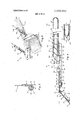
- FIG. 1 is a fragmentary perspective view of a spreader constructed in accordance withfltheinvention
- FIG. 2 is a fragmentary plan view of the spreader shown in FIG. 1, illustrating in phantom the limits of the angular, pivotal adjustment of which it is capable;
- FIG. 3 is an exploded perspective view of the spreader, a fragment only of the handle being shown;
- FIG. 4 is a fragmentary sectional view, partially ex ploded, taken generally along line IV IV of FIG. 2;
- FIG. 5 is a sectional view taken generally along line V V of FIG. 2, illustrating the hinge locking portion of the invention, the blade and blade cover plate having been omitted for clarity;
- FIG. 6 is a partially schematic illustration in perspective of the use of the invention.
- the disclosure relates to a device for spreading an adhesive coating over a flat surface.
- the invention is hereafter disclosed specifically with respect to an adhesive spreader used to spread beads of carpet adhesive prior to the laying of carpeting, it will be read.- ily apparent that it can be used for the spreading of other cements and adhesives as well. For example, it can be used to spread concrete over a flat base, particularly where a rough surface is desired.
- an adhesive spreader l0 is provided having an adhesive spreading portion 15, a frame member 40 hingedly mountingthe spreading portion, an operating handle 140, and pivoting means operatively connecting the handle to the frame member to control angular pivoting of the frame member with respect to the handle.
- a blade 20 is removably attached to a blade holder 22 by means such as threaded pins 23 and nuts 24.
- the blade has two rows 26 and 2 8 of differently spaced and sized teeth along opposite edges thereof.
- a cover or support plate 30 completes the mounting of the blade, being attached by the nuts with the blade between it and the housing.
- a flange portion 32 extends from one edge of plate 30 over and around the teeth row not being used, FIG. 4. It will be readily apparent that this assembly of the spreading portion is greatly simplified due to the use of a single blade, and can be readily disassembled for cleaning and/orchanging the teeth size or entire blade.
- the spreading portion is freely, hingedly'connected to the framing member 40 by means of a hinge 42 comprising hinge pins 44 at each end of the blade holder,
- the pin is provided with a'groove'52 extending around the circumference there-of. Asfshownparticularly. in FIGS. 3 and 5, this groove cooperates with a flexible strip 54 of metal riveted to the frame member 40 immediately above the knuckle 50, that knucklebeing provided with a hole or slot'56.
- -A handle or gripping portion 57 is provided and a flange portion 58 projects from the underside of the'strip 54 through slot 56 and into the groove 52.
- the stri'p 54 is sufficiently flexible to permit the strip to flex when gripping portion '57 is pulled away from the hinge, withdrawing flange portion 58. This action permits the hinge pin to be withdrawn.
- stops are placed on one or the other.
- the stops are preferably three stop flanges or tabs 62 and 64 integrally formed as part of the frame member,-tabs 62 extending out above (when inuse) the ,blade holder inbetween and adjacent to knuckles 48' and 50, while tab 64 projects below the blade holder,' the pivotal angle alpha between them being preferably'about 40 (FIG. 4).
- the stops are preferably three stop flanges or tabs 62 and 64 integrally formed as part of the frame member,-tabs 62 extending out above (when inuse) the ,blade holder inbetween and adjacent to knuckles 48' and 50, while tab 64 projects below the blade holder,' the pivotal angle alpha between them being preferably'about 40 (FIG. 4).
- the blade holder is hinged to a momentarily fixed position which causes it to slide across the substrate surface without chattering. This will either be the'position for pulling the spreader, shown in solid'in FIG. 4, or it is the position for pushing the spreader, shown-in phantom in FIG. 4. Preferably, this requires an angle gamma ofabout 40.
- means are provided for releasibly biasingthe spreading portion into one or the other of the aforesaid two positions.
- it is biased into the pull position-by a torsion spring 66 having center turns or loops 68 wrapped around the hinge pin, and end'portions 70 and 72 extending under the blade holder'22-and frame 40, respectively (FIGS. 2 and 3).
- the spring issufficiently flexible to permit the blade holder to be'hinged back against tab 64, mereiyb y pushing the spreader forward with a minimum amount of force, as will be readily appreciated.
- pivoting means 80 comprises a housing 82 pivoted at its end 84 to the approxi: mate center axis of the frame member 40 as defined by opening 85. Any pivot connection such as by a pin 86 having a grooved end, and snap washer 88, is suitable. From end 84, the housing extends backto a raised shoulder'90 two sides 92 and 93 of which are angled to define stops positioned about 240 apart (FIG. 2), for use in the operation of the pivoting means as described below.
- the housing continues back to define a track 94 having an centered groove 96, upon which is mounted a slide 98.
- the slide comprises a vertical flange 100 and a horizontal flange 102 having depending portions 103 defining a shoe riding over the track 94.
- Flange 102 is connected by a dowel pin 104 to a link arm 106 at end 108 thereof.
- the pin 104 is sufficiently long to ride within the groove 96, FIG. 4.
- the opposite end 110 of the link arm 106 is connected as by a pin' 112 identical to pin 86, to frame member 40 at an opening 114 offset from the center axis.
- the vertically extending flange 100 is pinned to one end 1 18 of a cylindrical lead screw member l20 having at least one spiraling groove 122 formed in its exterior, cylindrical surface.
- the opposite end 124 of member is linearly mounted within a journal portion 126 that is an extension of handie 140, the journal portion having attached to the interior surface thereof several pins 128, preferably fonned from hardened steel.
- the pins 128 project inwardly of the portion 126 and ride within'the groove 122.
- the journal portion 126 in turn is rotatably mounted within one or two bearings 130 mounted in raised portion 132 of the housing (FIG. 4), the bearings being preferably formed from nylon. Shoulder 134 of the portion 126 prohibits it from being pulled back out of the raised portion 132.
- member 120 is preferably singular, the assembly is simplified.
- the handle is then connected by its lower half 142 to journal portion 1261) a pin 144, the end 146 of lower half 142 serving to prevent forward movement of journal 126 (FIG. 4).
- the upper half 148 of the handle may be removably connected in a telescoping manner to the lower half by any conventional means, a spring lock l50 having button portions 152 being iliustrated as preferred.
- the handle 140 is long enough to permit erect operation, the two halves permitting easy storage.
- FIGS. 2, 4 and 6 in addition to that described above, it will be apparent that pulling or pushing adhesive with the spreader 10 over a floor 200 leaves beads 202.
- the operator handles spreader 10 in an erect position. Working from the top of FIG. 6 down, the excess adhesive 204 must be forced out beyond the edge of the spreader in the direction in which the next pass is to be made. Accordingly, handle 140 is simply rotated or twisted quickly as shown by arrow'220, causing lead screw member 120 to extend out of journal portion 126. This in turn causes link arm 106 to rotate the frame member counterclockwise about pivot pin 86 as shown in FIG. 2 until it abuts, as shown in phantom, against side 92 of shoulder 90. This defines an angle beta with the neutral position shown in solid, FIG. 2, which is preferably about 30.
- the adhesive is then pulled back in a pass overlapping the first pass, shown in FIG. 6 as being below that first pass.
- the excess adhesive 204 must be forced out of? the trailing edge, and since it is now being pulled, the frame member must be rotated in a clockwise direction as seen in FIG. 2 until it abuts against stop 93. This is accomplished by rotating handle 140 in the direction of arrow 222, FIG. 6, causing the lead screw member 120 to withdraw into the housing 82, to the position shown in phantom in FIG. 4.
- a spreader for use in spreading cementitious and adhesive material while working in an erect position comprising spreading means for contacting and spreading the material over a flat surface, a frame member freely hingedly connected to the spreading means by at least one hinge pin, said hinge pin having a groove extending around at least a portion of its circumference, means for releasibly locking the hinge pin within the spreading means and the frame member, said locking means including a flexible strip attached to said frame member and having a portion projecting from one side thereof into said groove, the strip having flexibility sufficient to permit it to be bent away from said groove, gripping means on said strip permitting it to be gripped and pulled away from said frame member, a handle pivotally mounting the frame member and having a length sufficient to permit a user to operate the spreader in an erect position, and means for pivoting the frame member with respect to the handle by rotating the handle about its long axis.
- said spreading means includes a blade and a blade holder, the holder .being hingedly connected to said frame member.
- a spreader for use in spreading cementitious and adhesive material while working in an erect position, comprising spreading means for contacting and spreading the material over a flat surface, a frame member mounting the spreading means, a handle pivotally mounting the member and having a length sufficient to permit a user to operate the spreader in an erect position, and means for pivoting the frame member with respect to the handle by twisting the handle, the spreading means and the frame member being characterized by means for freely hinging the one with respect to the other and by stop means for limiting the hinging to relative angular movement between one stop position and another stop position, whereby the spreading means may be freely hinged from one stop position t'oanother stop position by changing from a pushing movement to apulling movement.
- said hinging means includes a hinge pin and said biasing means includes a torsion spring a portion of which is wrapped around the hinge pin.
- said stop means includes at least two tabs projecting outwardly in two different planes from said frame member and adjacent to a portion of said hinging means, the planes of said tabs being angularly rotated with respect to each other by an angle of about 40.
- said hinging means includes a hinge pin, and further including means for releasibly locking the hinge pin within the spreading means and the frame member.
- said spreading means includes a blade and a blade holder, the holder being hingedly connected to said frame member.
- a spreader for use in spreading cementitious and adhesive material while working in an erect position, comprising spreading means for contacting and spreading the material over a flat surface, a frame member mounting the spreading means, a hollow handle operatively and pivotally mounted to the approximate center of said frame member and having a length sufficient to permit a user to operate the spreader in an erect position, and means for pivoting the frame member with respect to the handle by twisting the handle, the pivoting means including a single cylindrical member having at least one spiral groove formed therein, the cylindrical member being mounted within said handle for linear movement with respect thereto, a link arm operatively connected at one of its ends to said cylindrical member and at its opposite end to said frame member at a position offset from the center of the frame member, and at least one pin projecting from a portion of said handle into said spiral groove, whereby rotation of said handle causes said cylindrical member to advance or retract with respect to the handle and the link arm to pivot the frame member with respect to said handle.
- said pivoting means further includes a slide member, and a housing pivotally connected to said frame member and journaled to said handle, one end of said cylinder projecting into said housing and the other fixedly attached to the slide member, the slide member being pivotally attached to said link arm, the housing and said slide member including as a portion of one a track, and as a portion of the other a shoe slidably mounted with respect to said track.
- said hinging means includes a hinge pin, and further including means for releasibly locking the hinge pin within the spreading means and the frame member.
Abstract
A coating device for spreading adhesives, comprising a blade and mounting member hinged to a frame member between push and pull stops, the frame member being pivotally connected to a long handle by means causing the frame to pivot about an axis perpendicular to the handle, thus controlling the flow of excess adhesive.
Description
United States Patent [1 1 Glejt CARPET ADHESIVE SPREADER [75] Inventor: Robert G. Glejf, Des Plaines, I11.
[73] Assignee: Kinkead Industries Incorporated,
Chicago, Ill.
22 Filed: Dec. 7, 1972 21 Appl. No.: 313,009
[52] US. Cl. 15/104 S, 15/144 R [51] Int. Cl. E01c 19/00, B05c 11/02 [58] Field of Search... l5/235.6, 236 R, 105, 144 R, 15/235.8, 104 S; 306/10, 4, 3, 2; 404/97;
[56] i 7 References Cited I UNITED STATES PATENTS 3,611,470 10/1971 Gaston 15/235.6
[451 Apr. 16, 1974 12/1940 Hranicka 15/144 R 2/1958 Williams 15/236 R Primary Examiner-Leon G. Machlin Attorney, Agent, or Firm-Stanton T. Hadley; Dana M. Schmidt; Kenneth E. Roberts [5 7] ABSTRACT A coating device for spreading adhesives, comprising a blade and mounting member hinged to a frame member between push and pull stops, the frame member being pivotally connected to a long handle by means causing the frame to pivot about an axis perpendicular to the handle, thus controlling the flow of excess adhesive.
18 Claims, 6 Drawing Figures CARPET ADHESIVE SPREADER BACKGROUND OF THE INVENTION Carpeting is conventionally applied to substrate surfaces such as flooring or subflooring by means of conventional latex adhesive. Such adhesive in the past has been spread generally by means of a hand trowel, the workman accomplishing this on his hands and knees. It will be readily appreciated that such application is slow as well as tiring on the workman. With the advent of the high cost of labor, such slow methods of application can no longer be tolerated.
A recent innovation is an adhesive spreader which can be operated in an erect position. Developed by the Armstrong Cork Company, it features a complicated blade structure hinged to a frame member which is pivotably mounted on a handle releasibly locked to the member in any one of several angular positions. An example of such a spreader is shown in U. S. Pat. No. 3,611,470. Such aspreader has several disadvantages. The blade structure 'is not only expensive to make due to its complexity, it also is difficult and time-consuming to assemble. Although the blade structure is hinged to the frame, it is not freely hinged but rather fixed during use. Also, it is intended that the spreader be pulled only, the frame not permitting sufficient inclination back toward the applicator to prevent the blade from chattering when pushed. Finally, in order for the operator to change the angular orientation of the frame with respect to the handle, it is necessary that a catch be released and that the handle and operator be walked into the new orientation.
SUMMARY OF THE'INVENTION The invention relates to a spreader for cements and adhesives which can be operated in an erect position, simulating the movements of a hand trowel, and which avoids the disadvantages noted above in prior devices. More specifically, there is provided a spreader for use in spreading cementitious andadhesive material while working in an erect position, comprising spreading means for contacting and spreading the material over a flat surface, a frame member freely, hingedly connected to the spreading means by at least one hinge pin, means for releasibly locking the hinge pin within the spreading means and the frame member, a handle pivotally mounting the'frame member and having a length sufiicient to permit a user to operate the spreader in an erect position, and means for pivoting the frame member with respect to the handle by rotating the handle.
Stop means are further included for limiting the hinging of the spreading'me'ans with respect to the frame member to relative angular movement between two stop positions', and biasing means are provided for biasing the spreading means against one of the stop positions.
Accordingly, it is an object of the invention to pro- 'vide'a stand-up spreader device for spreading adhesives and cements, which lean be both pushed and pulled.
It is another object of the invention to provide such a device having a blade mechanism which is angularly adjustable quickly with respect to the handle.
It is a related object of the invention to provide such a device wherein the angular adjustment mechanism involves a minimum of parts, and in particular, only a single lead screw.
It is still another object of theinvention to provide sucha device wherein the blade mechanism isreadily and quickly disassembled and assembled for replacement.
Other objects and advantages will become apparent upon reference to the following description of the drawings and detailed discussion of the invention.
BRIEF DESCRIPTION OF THE DRAWINGS FIG. 1 is a fragmentary perspective view of a spreader constructed in accordance withfltheinvention;
FIG. 2 is a fragmentary plan view of the spreader shown in FIG. 1, illustrating in phantom the limits of the angular, pivotal adjustment of which it is capable;
FIG. 3 is an exploded perspective view of the spreader, a fragment only of the handle being shown;
FIG. 4 is a fragmentary sectional view, partially ex ploded, taken generally along line IV IV of FIG. 2;
FIG. 5 is a sectional view taken generally along line V V of FIG. 2, illustrating the hinge locking portion of the invention, the blade and blade cover plate having been omitted for clarity; and
FIG. 6 is a partially schematic illustration in perspective of the use of the invention.
DESCRIPTION OF THE PREFERRED EMBODIMENT The disclosure relates to a device for spreading an adhesive coating over a flat surface. Although the invention is hereafter disclosed specifically with respect to an adhesive spreader used to spread beads of carpet adhesive prior to the laying of carpeting, it will be read.- ily apparent that it can be used for the spreading of other cements and adhesives as well. For example, it can be used to spread concrete over a flat base, particularly where a rough surface is desired.
Turning now to FIGS. 1-5 in particular, an adhesive spreader l0is provided having an adhesive spreading portion 15, a frame member 40 hingedly mountingthe spreading portion, an operating handle 140, and pivoting means operatively connecting the handle to the frame member to control angular pivoting of the frame member with respect to the handle.
Referring specifically to the spreading portion l5, a blade 20 is removably attached to a blade holder 22 by means such as threaded pins 23 and nuts 24. To provide alternate sized and spaced teeth for different spreading patterns, the blade has two rows 26 and 2 8 of differently spaced and sized teeth along opposite edges thereof. A cover or support plate 30 completes the mounting of the blade, being attached by the nuts with the blade between it and the housing. To keep adhesive off the row of teeth not being used, a flange portion 32 extends from one edge of plate 30 over and around the teeth row not being used, FIG. 4. It will be readily apparent that this assembly of the spreading portion is greatly simplified due to the use of a single blade, and can be readily disassembled for cleaning and/orchanging the teeth size or entire blade.
In accordance with another aspect of the invention, the spreading portion is freely, hingedly'connected to the framing member 40 by means of a hinge 42 comprising hinge pins 44 at each end of the blade holder,
. 3 knuckles 46 on the blade holder, and two pairs of knuckles 48 and 50 on the frame member 40 (FIG. 3). To permit releasible engagement or locking of the hinge pin within' the hinge knuckles, the pin is provided with a'groove'52 extending around the circumference there-of. Asfshownparticularly. in FIGS. 3 and 5, this groove cooperates with a flexible strip 54 of metal riveted to the frame member 40 immediately above the knuckle 50, that knucklebeing provided with a hole or slot'56. -A handle or gripping portion 57 is provided and a flange portion 58 projects from the underside of the'strip 54 through slot 56 and into the groove 52. The stri'p 54 is sufficiently flexible to permit the strip to flex when gripping portion '57 is pulled away from the hinge, withdrawing flange portion 58. This action permits the hinge pin to be withdrawn.
In accordance with yetanother aspect of the invention, to limit the relative hinging of the blade holder with respect to the frame member to the desired angled positions, stops are placed on one or the other. Specifically as shown, the stops are preferably three stop flanges or tabs 62 and 64 integrally formed as part of the frame member,-tabs 62 extending out above (when inuse) the ,blade holder inbetween and adjacent to knuckles 48' and 50, while tab 64 projects below the blade holder,' the pivotal angle alpha between them beingpreferably'about 40 (FIG. 4). At any rate, whatever the value of alphaQthe tabs must be positioned so that when used,.as described. below, the blade holder is hinged to a momentarily fixed position which causes it to slide across the substrate surface without chattering. This will either be the'position for pulling the spreader, shown in solid'in FIG. 4, or it is the position for pushing the spreader, shown-in phantom in FIG. 4. Preferably, this requires an angle gamma ofabout 40.
To avoid having the blade holder flap indiscriminately back and forth, means are provided for releasibly biasingthe spreading portion into one or the other of the aforesaid two positions. Preferably, it is biased into the pull position-by a torsion spring 66 having center turns or loops 68 wrapped around the hinge pin, and end'portions 70 and 72 extending under the blade holder'22-and frame 40, respectively (FIGS. 2 and 3).
The spring issufficiently flexible to permit the blade holder to be'hinged back against tab 64, mereiyb y pushing the spreader forward with a minimum amount of force, as will be readily appreciated.
In accordance with still another aspect of the invention, frame member 40 operatively connected to handle 140 by'pivoting means 80, so that as described below, the handie need only be rotated ortwisted about its long axis and the frame member will pivot with respect thereto. Specifically, pivoting means 80 comprises a housing 82 pivoted at its end 84 to the approxi: mate center axis of the frame member 40 as defined by opening 85. Any pivot connection such as by a pin 86 having a grooved end, and snap washer 88, is suitable. From end 84, the housing extends backto a raised shoulder'90 two sides 92 and 93 of which are angled to define stops positioned about 240 apart (FIG. 2), for use in the operation of the pivoting means as described below. From shoulder 90, the housing continues back to define a track 94 having an centered groove 96, upon which is mounted a slide 98. The slide comprises a vertical flange 100 and a horizontal flange 102 having depending portions 103 defining a shoe riding over the track 94. Flange 102 is connected by a dowel pin 104 to a link arm 106 at end 108 thereof. .The pin 104 is sufficiently long to ride within the groove 96, FIG. 4. The opposite end 110 of the link arm 106 is connected as by a pin' 112 identical to pin 86, to frame member 40 at an opening 114 offset from the center axis.
The vertically extending flange 100 is pinned to one end 1 18 of a cylindrical lead screw member l20 having at least one spiraling groove 122 formed in its exterior, cylindrical surface. The opposite end 124 of member is linearly mounted within a journal portion 126 that is an extension of handie 140, the journal portion having attached to the interior surface thereof several pins 128, preferably fonned from hardened steel. The pins 128 project inwardly of the portion 126 and ride within'the groove 122. The journal portion 126 in turn is rotatably mounted within one or two bearings 130 mounted in raised portion 132 of the housing (FIG. 4), the bearings being preferably formed from nylon. Shoulder 134 of the portion 126 prohibits it from being pulled back out of the raised portion 132. As member 120 is preferably singular, the assembly is simplified.
The handle is then connected by its lower half 142 to journal portion 1261) a pin 144, the end 146 of lower half 142 serving to prevent forward movement of journal 126 (FIG. 4). The upper half 148 of the handle may be removably connected in a telescoping manner to the lower half by any conventional means, a spring lock l50 having button portions 152 being iliustrated as preferred. The handle 140 is long enough to permit erect operation, the two halves permitting easy storage.
OPERATION Turning now especially to FIGS. 2, 4 and 6, in addition to that described above, it will be apparent that pulling or pushing adhesive with the spreader 10 over a floor 200 leaves beads 202. The operator handles spreader 10 in an erect position. Working from the top of FIG. 6 down, the excess adhesive 204 must be forced out beyond the edge of the spreader in the direction in which the next pass is to be made. Accordingly, handle 140 is simply rotated or twisted quickly as shown by arrow'220, causing lead screw member 120 to extend out of journal portion 126. This in turn causes link arm 106 to rotate the frame member counterclockwise about pivot pin 86 as shown in FIG. 2 until it abuts, as shown in phantom, against side 92 of shoulder 90. This defines an angle beta with the neutral position shown in solid, FIG. 2, which is preferably about 30.
After proceeding preferably a, short distance in this fashion, the adhesive is then pulled back in a pass overlapping the first pass, shown in FIG. 6 as being below that first pass. Again, the excess adhesive 204 must be forced out of? the trailing edge, and since it is now being pulled, the frame member must be rotated in a clockwise direction as seen in FIG. 2 until it abuts against stop 93. This is accomplished by rotating handle 140 in the direction of arrow 222, FIG. 6, causing the lead screw member 120 to withdraw into the housing 82, to the position shown in phantom in FIG. 4.
The pushing and pulling is thus repeated until the entire floor is coated, imitating in general the movements that would be made by a hand trowel if the operator were on his hands and knees. Other spreading methods will also be apparent to the skilled operator.
Although the invention has been described in connection with certain preferred embodiments, it is not limited thereto. Rather, it is intended that it cover all arrangements, alternate embodiments, and equivalents as may be included within the scope of the following claims.
What is claimed is:
l. A spreader for use in spreading cementitious and adhesive material while working in an erect position, comprising spreading means for contacting and spreading the material over a flat surface, a frame member freely hingedly connected to the spreading means by at least one hinge pin, said hinge pin having a groove extending around at least a portion of its circumference, means for releasibly locking the hinge pin within the spreading means and the frame member, said locking means including a flexible strip attached to said frame member and having a portion projecting from one side thereof into said groove, the strip having flexibility sufficient to permit it to be bent away from said groove, gripping means on said strip permitting it to be gripped and pulled away from said frame member, a handle pivotally mounting the frame member and having a length sufficient to permit a user to operate the spreader in an erect position, and means for pivoting the frame member with respect to the handle by rotating the handle about its long axis.
2. The spreader as defined in claim 1, wherein said spreading means includes a blade and a blade holder, the holder .being hingedly connected to said frame member.
3. The spreader as defined in claim 2, wherein said blade is defined by two opposed, generally parallel working edges each having a row of teeth sized and spaced differently from the other.
4. The spreader as defined in claim 3, and further including a support plate attached to'said blade holder with said blade'inbetween.
5. The spreader as defined in claim 4, wherein said support plate includes a portion extending over and covering one of said working edges.
6. A spreader for use in spreading cementitious and adhesive material while working in an erect position, comprising spreading means for contacting and spreading the material over a flat surface, a frame member mounting the spreading means, a handle pivotally mounting the member and having a length sufficient to permit a user to operate the spreader in an erect position, and means for pivoting the frame member with respect to the handle by twisting the handle, the spreading means and the frame member being characterized by means for freely hinging the one with respect to the other and by stop means for limiting the hinging to relative angular movement between one stop position and another stop position, whereby the spreading means may be freely hinged from one stop position t'oanother stop position by changing from a pushing movement to apulling movement.
7. The spreader as defined in claim 6, and further including means for biasing the spreading means against the stop means in one of said stop positions.
; 8. The spreader as defined in claim 7, wherein said hinging means includes a hinge pin and said biasing means includes a torsion spring a portion of which is wrapped around the hinge pin.
9. The spreader as defined in claim 6, wherein said stop means includes at least two tabs projecting outwardly in two different planes from said frame member and adjacent to a portion of said hinging means, the planes of said tabs being angularly rotated with respect to each other by an angle of about 40.
10. The spreader as defined in claim 6, wherein said hinging means includes a hinge pin, and further including means for releasibly locking the hinge pin within the spreading means and the frame member.
11. The spreader as defined in claim 6, wherein said spreading means includes a blade and a blade holder, the holder being hingedly connected to said frame member.
12. A spreader for use in spreading cementitious and adhesive material while working in an erect position, comprising spreading means for contacting and spreading the material over a flat surface, a frame member mounting the spreading means, a hollow handle operatively and pivotally mounted to the approximate center of said frame member and having a length sufficient to permit a user to operate the spreader in an erect position, and means for pivoting the frame member with respect to the handle by twisting the handle, the pivoting means including a single cylindrical member having at least one spiral groove formed therein, the cylindrical member being mounted within said handle for linear movement with respect thereto, a link arm operatively connected at one of its ends to said cylindrical member and at its opposite end to said frame member at a position offset from the center of the frame member, and at least one pin projecting from a portion of said handle into said spiral groove, whereby rotation of said handle causes said cylindrical member to advance or retract with respect to the handle and the link arm to pivot the frame member with respect to said handle.
13. The spreader as defined in claim 12, wherein said pivoting means further includes a slide member, and a housing pivotally connected to said frame member and journaled to said handle, one end of said cylinder projecting into said housing and the other fixedly attached to the slide member, the slide member being pivotally attached to said link arm, the housing and said slide member including as a portion of one a track, and as a portion of the other a shoe slidably mounted with respect to said track.
14. The spreader as defined in claim 13, wherein said track is a portion of said housing.
15. The spreader as defined in claim 12, and further including hinging means for freely, hingedly mounting said spreading means with respect to said frame member.
16. The spreader as defined in claim 15, wherein said hinging means includes a hinge pin, and further including means for releasibly locking the hinge pin within the spreading means and the frame member.
17. The spreader as defined in claim 15, and further including stop means for limiting the hinging to relative angular movement between one stop position and another stop position, whereby the spreading means may be freely hinged from one stop position to another stop member.
Claims (18)
1. A spreader for use in spreading cementitious and adhesive material while working in an erect position, comprising spreading means for contacting and spreading the material over a flat surface, a frame member freely hingedly connected to the spreading means by at least one hinge pin, said hinge pin having a groove extending around at least a portion of its circumference, means for releasibly locking the hinge pin within the spreading means and the frame member, said locking means including a flexible strip attached to said frame member and having a portion projecting from one side thereof into said groove, the strip having flexibility sufficient to permit it to be bent away from said groove, gripping means on said strip permitting it to be gripped and pulled away from said frame member, a handle pivotally mounting the frame member and having a length sufficient to permit a user to operate the spreader in an erect position, and means for pivoting the frame member with respect to the handle by rotating the handle about its long axis.
2. The spreader as defined in claim 1, wherein said spreading means includes a blade and a blade holder, the holder being hingedly connected to said frame member.
3. The spreader as defined in claim 2, wherein said blade is defined by two opposed, generally parallel working edges each having a row of teeth sized and spaced differently from the other.
4. The spreader as defined in claim 3, and Further including a support plate attached to said blade holder with said blade inbetween.
5. The spreader as defined in claim 4, wherein said support plate includes a portion extending over and covering one of said working edges.
6. A spreader for use in spreading cementitious and adhesive material while working in an erect position, comprising spreading means for contacting and spreading the material over a flat surface, a frame member mounting the spreading means, a handle pivotally mounting the member and having a length sufficient to permit a user to operate the spreader in an erect position, and means for pivoting the frame member with respect to the handle by twisting the handle, the spreading means and the frame member being characterized by means for freely hinging the one with respect to the other and by stop means for limiting the hinging to relative angular movement between one stop position and another stop position, whereby the spreading means may be freely hinged from one stop position to another stop position by changing from a pushing movement to a pulling movement.
7. The spreader as defined in claim 6, and further including means for biasing the spreading means against the stop means in one of said stop positions.
8. The spreader as defined in claim 7, wherein said hinging means includes a hinge pin and said biasing means includes a torsion spring a portion of which is wrapped around the hinge pin.
9. The spreader as defined in claim 6, wherein said stop means includes at least two tabs projecting outwardly in two different planes from said frame member and adjacent to a portion of said hinging means, the planes of said tabs being angularly rotated with respect to each other by an angle of about 40*.
10. The spreader as defined in claim 6, wherein said hinging means includes a hinge pin, and further including means for releasibly locking the hinge pin within the spreading means and the frame member.
11. The spreader as defined in claim 6, wherein said spreading means includes a blade and a blade holder, the holder being hingedly connected to said frame member.
12. A spreader for use in spreading cementitious and adhesive material while working in an erect position, comprising spreading means for contacting and spreading the material over a flat surface, a frame member mounting the spreading means, a hollow handle operatively and pivotally mounted to the approximate center of said frame member and having a length sufficient to permit a user to operate the spreader in an erect position, and means for pivoting the frame member with respect to the handle by twisting the handle, the pivoting means including a single cylindrical member having at least one spiral groove formed therein, the cylindrical member being mounted within said handle for linear movement with respect thereto, a link arm operatively connected at one of its ends to said cylindrical member and at its opposite end to said frame member at a position offset from the center of the frame member, and at least one pin projecting from a portion of said handle into said spiral groove, whereby rotation of said handle causes said cylindrical member to advance or retract with respect to the handle and the link arm to pivot the frame member with respect to said handle.
13. The spreader as defined in claim 12, wherein said pivoting means further includes a slide member, and a housing pivotally connected to said frame member and journaled to said handle, one end of said cylinder projecting into said housing and the other fixedly attached to the slide member, the slide member being pivotally attached to said link arm, the housing and said slide member including as a portion of one a track, and as a portion of the other a shoe slidably mounted with respect to said track.
14. The spreader as defined in claim 13, wherein said track is a portion of said housing.
15. The spreader as defined in claim 12, and further including hinging means for freely, hingedly mounting said spReading means with respect to said frame member.
16. The spreader as defined in claim 15, wherein said hinging means includes a hinge pin, and further including means for releasibly locking the hinge pin within the spreading means and the frame member.
17. The spreader as defined in claim 15, and further including stop means for limiting the hinging to relative angular movement between one stop position and another stop position, whereby the spreading means may be freely hinged from one stop position to another stop position depending upon whether the device is pushed or pulled, by changing from a pushing movement to a pulling movement.
18. The spreader as defined in claim 11, wherein said spreading means includes a blade and a blade holder, the holder being hingedly connected to said frame member.
Priority Applications (1)
| Application Number | Priority Date | Filing Date | Title |
|---|---|---|---|
| US00313009A US3803662A (en) | 1972-12-07 | 1972-12-07 | Carpet adhesive spreader |
Applications Claiming Priority (1)
| Application Number | Priority Date | Filing Date | Title |
|---|---|---|---|
| US00313009A US3803662A (en) | 1972-12-07 | 1972-12-07 | Carpet adhesive spreader |
Publications (1)
| Publication Number | Publication Date |
|---|---|
| US3803662A true US3803662A (en) | 1974-04-16 |
Family
ID=23213986
Family Applications (1)
| Application Number | Title | Priority Date | Filing Date |
|---|---|---|---|
| US00313009A Expired - Lifetime US3803662A (en) | 1972-12-07 | 1972-12-07 | Carpet adhesive spreader |
Country Status (1)
| Country | Link |
|---|---|
| US (1) | US3803662A (en) |
Cited By (19)
| Publication number | Priority date | Publication date | Assignee | Title |
|---|---|---|---|---|
| US4229032A (en) * | 1979-03-09 | 1980-10-21 | The Murphy Advantage Corporation | Universal implement for cleaning corrugated surfaces |
| US4856932A (en) * | 1988-05-04 | 1989-08-15 | Simon Kraft | Concrete finishing float having spirally slotted sleeve |
| US4892437A (en) * | 1988-05-23 | 1990-01-09 | Simon Kraft | Concrete finishing float with rear fitting bar |
| US4982470A (en) * | 1989-09-26 | 1991-01-08 | S. Szabo Ag | Apparatus for applying of an adhesive for floor coverings |
| US5379479A (en) * | 1992-12-31 | 1995-01-10 | Nelson; Jim L. | Adhesive spreader |
| US6295689B1 (en) * | 1998-12-02 | 2001-10-02 | Phillip George Sciacca | Wipe-down knife |
| EP1149963A1 (en) * | 2000-04-28 | 2001-10-31 | Rudolf Dilly | Spatula |
| US6408479B1 (en) * | 1999-04-08 | 2002-06-25 | Steve B. Pinney | Articulated paint roller assembly |
| US20040173145A1 (en) * | 2001-06-13 | 2004-09-09 | Peter Rytter | Apparatus for the spreading of adhesive material |
| WO2004105962A1 (en) * | 2003-05-29 | 2004-12-09 | Atsushi Miyaoka | Coater used also as wiper |
| US20050251945A1 (en) * | 2004-05-14 | 2005-11-17 | Ryan Fortune | Spreader for floor dressing material |
| US20060137125A1 (en) * | 2004-12-28 | 2006-06-29 | Herbert Goller | Weighted trowel with elongated handle |
| US7396187B1 (en) | 2005-01-26 | 2008-07-08 | Beno J. Gundiach Company | Upright trowel |
| EP2017405A2 (en) | 2007-07-20 | 2009-01-21 | Bostik SA | Applicator with notched filling knife and adhesive composition for installing parquet flooring |
| US20090044364A1 (en) * | 2007-07-20 | 2009-02-19 | Bostik S.A. | Notched spatula applicator and adhesive composition for laying parquet |
| US7752703B1 (en) * | 2005-06-09 | 2010-07-13 | Edward Silva | Articulated apparatus flat blade hand tool |
| WO2012011004A1 (en) | 2010-07-02 | 2012-01-26 | Udviklingsselskabet Af 2002 Aps | Apparatus for the spreading of adhesive material |
| WO2021155424A1 (en) * | 2020-02-07 | 2021-08-12 | Roy Tiles Pty Limited | Handle attachment for an adhesive spreader |
| US11235349B2 (en) | 2012-06-25 | 2022-02-01 | 3M Innovative Properties Company | Devices for coating contoured surfaces |
Citations (3)
| Publication number | Priority date | Publication date | Assignee | Title |
|---|---|---|---|---|
| US2226817A (en) * | 1938-04-21 | 1940-12-31 | Albert C Hranicka | Floor cleaner |
| US2824330A (en) * | 1956-11-02 | 1958-02-25 | Consumers Glue Company | Spreader for cement and the like |
| US3611470A (en) * | 1970-06-08 | 1971-10-12 | Armstrong Cork Co | Adhesive spreader |
-
1972
- 1972-12-07 US US00313009A patent/US3803662A/en not_active Expired - Lifetime
Patent Citations (3)
| Publication number | Priority date | Publication date | Assignee | Title |
|---|---|---|---|---|
| US2226817A (en) * | 1938-04-21 | 1940-12-31 | Albert C Hranicka | Floor cleaner |
| US2824330A (en) * | 1956-11-02 | 1958-02-25 | Consumers Glue Company | Spreader for cement and the like |
| US3611470A (en) * | 1970-06-08 | 1971-10-12 | Armstrong Cork Co | Adhesive spreader |
Cited By (24)
| Publication number | Priority date | Publication date | Assignee | Title |
|---|---|---|---|---|
| US4229032A (en) * | 1979-03-09 | 1980-10-21 | The Murphy Advantage Corporation | Universal implement for cleaning corrugated surfaces |
| US4856932A (en) * | 1988-05-04 | 1989-08-15 | Simon Kraft | Concrete finishing float having spirally slotted sleeve |
| US4892437A (en) * | 1988-05-23 | 1990-01-09 | Simon Kraft | Concrete finishing float with rear fitting bar |
| US4982470A (en) * | 1989-09-26 | 1991-01-08 | S. Szabo Ag | Apparatus for applying of an adhesive for floor coverings |
| US5379479A (en) * | 1992-12-31 | 1995-01-10 | Nelson; Jim L. | Adhesive spreader |
| US6295689B1 (en) * | 1998-12-02 | 2001-10-02 | Phillip George Sciacca | Wipe-down knife |
| US6408479B1 (en) * | 1999-04-08 | 2002-06-25 | Steve B. Pinney | Articulated paint roller assembly |
| EP1149963A1 (en) * | 2000-04-28 | 2001-10-31 | Rudolf Dilly | Spatula |
| US20040173145A1 (en) * | 2001-06-13 | 2004-09-09 | Peter Rytter | Apparatus for the spreading of adhesive material |
| US7138015B2 (en) | 2001-06-13 | 2006-11-21 | Udviklingsselskabet Af 2002 Aps | Apparatus for the spreading of adhesive material |
| JPWO2004105962A1 (en) * | 2003-05-29 | 2006-07-20 | 宮岡 厚 | Wiper combined applicator |
| WO2004105962A1 (en) * | 2003-05-29 | 2004-12-09 | Atsushi Miyaoka | Coater used also as wiper |
| US7506399B2 (en) | 2004-05-14 | 2009-03-24 | Ardex, L.P. | Spreader for floor dressing material |
| US20050251945A1 (en) * | 2004-05-14 | 2005-11-17 | Ryan Fortune | Spreader for floor dressing material |
| US7464432B2 (en) | 2004-12-28 | 2008-12-16 | Ardex, L.P. | Weighted trowel with elongated handle |
| US20060137125A1 (en) * | 2004-12-28 | 2006-06-29 | Herbert Goller | Weighted trowel with elongated handle |
| US7396187B1 (en) | 2005-01-26 | 2008-07-08 | Beno J. Gundiach Company | Upright trowel |
| US7752703B1 (en) * | 2005-06-09 | 2010-07-13 | Edward Silva | Articulated apparatus flat blade hand tool |
| US20090044364A1 (en) * | 2007-07-20 | 2009-02-19 | Bostik S.A. | Notched spatula applicator and adhesive composition for laying parquet |
| EP2017405A2 (en) | 2007-07-20 | 2009-01-21 | Bostik SA | Applicator with notched filling knife and adhesive composition for installing parquet flooring |
| US8272095B2 (en) | 2007-07-20 | 2012-09-25 | Bostik S.A. | Notched spatula applicator and adhesive composition for laying parquet |
| WO2012011004A1 (en) | 2010-07-02 | 2012-01-26 | Udviklingsselskabet Af 2002 Aps | Apparatus for the spreading of adhesive material |
| US11235349B2 (en) | 2012-06-25 | 2022-02-01 | 3M Innovative Properties Company | Devices for coating contoured surfaces |
| WO2021155424A1 (en) * | 2020-02-07 | 2021-08-12 | Roy Tiles Pty Limited | Handle attachment for an adhesive spreader |
Similar Documents
| Publication | Publication Date | Title |
|---|---|---|
| US3803662A (en) | Carpet adhesive spreader | |
| US4219899A (en) | Paint pad assembly | |
| US4085703A (en) | Painting shield | |
| US20110139068A1 (en) | Flat box finisher | |
| US4982470A (en) | Apparatus for applying of an adhesive for floor coverings | |
| US3359589A (en) | Painting device | |
| US4467495A (en) | Vacuum cleaner nozzle lift device | |
| US10533326B2 (en) | Plaster taping apparatus and attachments | |
| EP1964644A1 (en) | Motor-driven grinder | |
| JPH0316548A (en) | Holder for mop and pad | |
| US7752703B1 (en) | Articulated apparatus flat blade hand tool | |
| CA2302039C (en) | Mops and mop components | |
| US2498980A (en) | Self-feeding applicator | |
| US20030101527A1 (en) | Mops and mop components | |
| US3263263A (en) | Paint roller device | |
| US4038716A (en) | Swingable yielding paint roller | |
| US4055384A (en) | Roofing apparatus | |
| EP0808669B1 (en) | Tool for the application of paint, glue or any other material requiring smoothing | |
| JPS584640B2 (en) | Straight ruler support device for rail type flexible parallel ruler | |
| US20040211525A1 (en) | Tape machine and wiper | |
| US3109755A (en) | Paint roller guide | |
| US20090047055A1 (en) | Device for applying a uniform coating of floor finish | |
| US5845359A (en) | Paint and coatings applicator | |
| US6012865A (en) | Remote control multi position paint roller frame | |
| AU614837B2 (en) | Improvements in paint roller |