US37892A - Improvement in horse-powers - Google Patents
Improvement in horse-powers Download PDFInfo
- Publication number
- US37892A US37892A US37892DA US37892A US 37892 A US37892 A US 37892A US 37892D A US37892D A US 37892DA US 37892 A US37892 A US 37892A
- Authority
- US
- United States
- Prior art keywords
- rolls
- chain
- horse
- platform
- endless
- Prior art date
- Legal status (The legal status is an assumption and is not a legal conclusion. Google has not performed a legal analysis and makes no representation as to the accuracy of the status listed.)
- Expired - Lifetime
Links
- 239000002023 wood Substances 0.000 description 4
- 230000001154 acute effect Effects 0.000 description 3
- 238000010586 diagram Methods 0.000 description 3
- XEEYBQQBJWHFJM-UHFFFAOYSA-N Iron Chemical compound [Fe] XEEYBQQBJWHFJM-UHFFFAOYSA-N 0.000 description 2
- 230000001788 irregular Effects 0.000 description 2
- 229910052742 iron Inorganic materials 0.000 description 1
- 230000000284 resting effect Effects 0.000 description 1
- 230000002459 sustained effect Effects 0.000 description 1
Images

Classifications
-
- A—HUMAN NECESSITIES
- A63—SPORTS; GAMES; AMUSEMENTS
- A63B—APPARATUS FOR PHYSICAL TRAINING, GYMNASTICS, SWIMMING, CLIMBING, OR FENCING; BALL GAMES; TRAINING EQUIPMENT
- A63B22/00—Exercising apparatus specially adapted for conditioning the cardio-vascular system, for training agility or co-ordination of movements
- A63B22/0015—Exercising apparatus specially adapted for conditioning the cardio-vascular system, for training agility or co-ordination of movements with an adjustable movement path of the support elements
- A63B22/0023—Exercising apparatus specially adapted for conditioning the cardio-vascular system, for training agility or co-ordination of movements with an adjustable movement path of the support elements the inclination of the main axis of the movement path being adjustable, e.g. the inclination of an endless band
Definitions
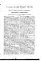
- FIG. 1 is a top view or plan.
- Fig. 2 is a side elevation of the machine complete, represented with the platform-chain resting on the periphery ofthe supporting rolls.
- Fig. 3 is an end view.
- Fig. 4 is a transverse section through the center of the machine, showing the driving-gear coggin g into the endless plat form-chain, also showing the position of the stationary rolls that support the return of the endless platform.
- FIG. 5 is a top view of a detached section of the endless platform, representing one under tread and two links.
- FIG. 6 is an end view of a detached section of the endless platform, with two links showin g the projecting boss.
- Fig. 7 is a top view of the supporting-chain with roll showing the connecting-bar.
- Fig. Sis a diagram showing the supporting-rolls in two extreme positions, and ihe angles of the connecting-links on the end track.
- Fig. 9 is a dia-gram showing the supporting-rolls in two extreme positions with the links at right angles, showing the deiiciency of the tension of the chain in the different positions on the end track.
- Fig. 10 is a diagram showing the supporting-rolls and chain-links in two extreme positions on the end track, also showing the combination of length of link and diameter of end track and supporting-rolls and their angles, so constructed as to pass the end track with the same tension of chain.
- the nature of my invention consists in constructing endless chain horse-powers in such a manner that the connecting-chain links of the moving platform shall be kept firmly in their proper position by a hollow boss or tube passing nearly through the tread-wood, and thus relieving the tread-bolt in a great measure of its strain 5 also, by placing the drivinggear directly under the horse and having the gear cog into both the upper and under gears of the moving platform also, making the connecting-links of the supportingrolls connected at or near their center, hy which device the rolls are guided more perfectly in their track also, making such length of linkto the supporting-rolls and diameter of the semi-circle or end track, that the sections ofthe endy less chain may pass the spuri-circlctrack at an acute angle without causing a jerking or irregular tension.
- This device We are en abled to construct horse-powers .with a less number of supporting-rolls and connectinglinks, making the machine much lowerat the rear end, thus saving in cost.
- a is a link withV projecting boss .1", which passes nearly through the wood tread, represented by the dotted lines.
- c is the screw that holds the tread on the boss.
- E is the moving platform-chain.
- f is the drive-wheel.
- g is the stationary supportingwheels for the return-platform when it is supported on periphery-rolls.
- lt will be seen as the horse propels the top of the drive-wheel that the bottom will propel the retnrnin g platform-chain with less loss of power than it would require to draw it around the end track with any considerable angle of chain-links.
- Fig. 10 so operates as to give a free and regular motion and equal tension to the chain in all its positions in passing the end track.
- This is shown by the different positions of the chainlinks h 71, IL h and rolls m m in. one extreme position and links lL It h h and rolls o o o in the other position, and it will be seen the tension of the chain is the i when the length of link is such as to pass the end track at a right angle, as' shown by the fracture in roll m in Fig. 9, which represents the usual mode of constructing horse-powers; but by this device the chain passes the end track at a more acute angle, making a saving Ain the height of the machine.
Landscapes
- Health & Medical Sciences (AREA)
- Cardiology (AREA)
- Vascular Medicine (AREA)
- General Health & Medical Sciences (AREA)
- Physical Education & Sports Medicine (AREA)
- Escalators And Moving Walkways (AREA)
Description
UNITED STATES PATENT OFFICE.
GEORGE E. BURT, OF HARVARD,` MASSACHUSETTS.
' IMPROVEMENT IN HORSE-POWERS.A
Specification forming part of Letters Patent No. 37,892, dated March 17, 1863.
Mode of Constructing Horse-Powers; and I.
do hereby declare that the following is a full, clear, and exact description thereof, reference being had to the accompanying drawings, and to the letters of reference marked thereon, in whichi Figure 1 is a top view or plan. Fig. 2 is a side elevation of the machine complete, represented with the platform-chain resting on the periphery ofthe supporting rolls. Fig. 3 is an end view. Fig. 4 is a transverse section through the center of the machine, showing the driving-gear coggin g into the endless plat form-chain, also showing the position of the stationary rolls that support the return of the endless platform. Fig. 5 is a top view of a detached section of the endless platform, representing one under tread and two links. Fig. 6 is an end view of a detached section of the endless platform, with two links showin g the projecting boss. Fig. 7 is a top view of the supporting-chain with roll showing the connecting-bar. Fig. Sis a diagram showing the supporting-rolls in two extreme positions, and ihe angles of the connecting-links on the end track. Fig. 9 is a dia-gram showing the supporting-rolls in two extreme positions with the links at right angles, showing the deiiciency of the tension of the chain in the different positions on the end track. Fig. 10 is a diagram showing the supporting-rolls and chain-links in two extreme positions on the end track, also showing the combination of length of link and diameter of end track and supporting-rolls and their angles, so constructed as to pass the end track with the same tension of chain.
Like letters represent like parts.
The nature of my invention consists in constructing endless chain horse-powers in such a manner that the connecting-chain links of the moving platform shall be kept firmly in their proper position by a hollow boss or tube passing nearly through the tread-wood, and thus relieving the tread-bolt in a great measure of its strain 5 also, by placing the drivinggear directly under the horse and having the gear cog into both the upper and under gears of the moving platform also, making the connecting-links of the supportingrolls connected at or near their center, hy which device the rolls are guided more perfectly in their track also, making such length of linkto the supporting-rolls and diameter of the semi-circle or end track, that the sections ofthe endy less chain may pass the seini-circlctrack at an acute angle without causing a jerking or irregular tension. By this device We are en abled to construct horse-powers .with a less number of supporting-rolls and connectinglinks, making the machine much lowerat the rear end, thus saving in cost.
The most 'of these improvements may he used on machines constructed with the supportingvrolls pivoted directly to the platformchain.
lt is well known that the bolts that attachv the wood treads break and get loose, caused y by the continual strain and jar ofthe horse traveling onthem. To-obviate this difficulty l have a hollow boss cast on the chaiulink that passes nearly through the wood tread4 and takes the strain of the horse and serves also to keep the iron link firm and level. This is shown in Figs. 5 and 6.
a is a link withV projecting boss .1", which passes nearly through the wood tread, represented by the dotted lines.
c is the screw that holds the tread on the boss.
On all endless-chain machines thereis a loss of power in getting the sections of the chain around the end track, and the loss increases as the angles of the chain are increased. To overcome this difficultyI construct myrnachine with the Adrive-wheel so as to gear both into the top and bottom of the moving platl Y form, by which device the angles of the-,chain i on the end track are relieved of the labor of drawing the platform up the inclined plane. This is shown in Fig. 4.
E is the moving platform-chain. f is the drive-wheel. g is the stationary supportingwheels for the return-platform when it is supported on periphery-rolls. lt will be seen as the horse propels the top of the drive-wheel that the bottom will propel the retnrnin g platform-chain with less loss of power than it would require to draw it around the end track with any considerable angle of chain-links.
There has ever been serious difficulty in running horse-powers on the periphery of supporting-rolls, by reason of the connecting-links of the rolls and the pivots on which the rolls turn becoming worn, therefore allowing one side of the link to get in advance of -tlle other and the rolls to get out of a right line with the Wthe pivot at right angles with the links.
1t is necessary that portable horse-powers should be as low as possible at the rear end. 'therefore it is desirable to pass the links to the supportingrolls around the end track at the most acute angle practicable, whether they are pivoted to the platform or otherwise, and at the same time to avoid irregular tension of chain. v
The operation ofthe machine with these improvements is as follows: By the device ofthe cog-wheelf, cogging int o the endless platform, both at the top and bottom, and being pl'aced under the horse when the .horse propels the upper portion of the endless platform, the cog- W-heelf propels the under portion of the endless platform on the straight track, and thereby entirely relieving the connectir'ig-joints of all the strain and friction caused by the labor of thev horse while the sections are at angles passing the end track also, the power is given'directly to the top of the gear-wheel f always at the same point, by which means the horse gives more effective power, and by the device of the combination the chain-link and diameter of end track and supporting-roll, as
shown in Fig. 10, so operates as to give a free and regular motion and equal tension to the chain in all its positions in passing the end track. This is shown by the different positions of the chainlinks h 71, IL h and rolls m m in. one extreme position and links lL It h h and rolls o o o in the other position, and it will be seen the tension of the chain is the i when the length of link is such as to pass the end track at a right angle, as' shown by the fracture in roll m in Fig. 9, which represents the usual mode of constructing horse-powers; but by this device the chain passes the end track at a more acute angle, making a saving Ain the height of the machine. lt also brings the upper and lower parts of the endless chain nearer together, by which means the drivingcogfis of less diameter, kconsequently giving more speed. The projecting boss r in Fig. 6 holds the link rm in its position and relieves the bolt that secures the wood-tread to the link from unequal strain. When the endless platform is supported on the periphery of the supporting-rolls, the rolls are guided lin their proper track by the links h h and bar'yv in'Fivg.,`Y 7 and anges on the supporting-rolls andj The stationary wheels g in support the return or bottom portion of the endless platform; but when the platform is supported on axles the rolls are pivoted ditrack.
rectly tothe endless platform, as is shown in Fig. l0. The supporting-rolls so attached will 'Y support the endless chain both at the top, bottom, and end tracks. It will be seen by giving motion to the endless platform at the top theA i cog wheelfwill propel the endless platform up the inclined plane of the bottom track, p, and roundthe end track, the endless platform being sustained by the supporting rolls, and the sections passing theend track with a smooth, regular motion, avoiding the usual jerking 3. The connecting Aof the links h h by the bar j, for the purpose described.
4.. The combination of the link h with the dsupporting-rolls and end track, constructed and operating substantially in the manner specified, and for the purposes set forth.
GEORGE E. BURT. Witnesses: n
J AMns M. BARRY, AUG. G. HILL.
Publications (1)
| Publication Number | Publication Date |
|---|---|
| US37892A true US37892A (en) | 1863-03-17 |
Family
ID=2107466
Family Applications (1)
| Application Number | Title | Priority Date | Filing Date |
|---|---|---|---|
| US37892D Expired - Lifetime US37892A (en) | Improvement in horse-powers |
Country Status (1)
| Country | Link |
|---|---|
| US (1) | US37892A (en) |
-
0
- US US37892D patent/US37892A/en not_active Expired - Lifetime
Similar Documents
| Publication | Publication Date | Title |
|---|---|---|
| US8028A (en) | Hokse-poweb | |
| US37892A (en) | Improvement in horse-powers | |
| US5001A (en) | Horse-power | |
| US22848A (en) | Improvement in steam-plows | |
| US35062A (en) | Stuart perry | |
| US504394A (en) | Transfer mechanism for rolling-mills | |
| US411986A (en) | Animal tread-power | |
| US306961A (en) | William f | |
| US283751A (en) | Chain-link | |
| US206837A (en) | Improvement in stump-extractors | |
| US161663A (en) | Improvement in horse-powers | |
| US27928A (en) | House-power | |
| US33024A (en) | Endless chain and tread of horse-power | |
| US1178408A (en) | Elevating-conveyer. | |
| US219237A (en) | Improvement in stump-extractors | |
| US382857A (en) | batter | |
| US202679A (en) | Improvement in dog-powers | |
| US203320A (en) | Improvement in horse-powers | |
| US81004A (en) | Improvement in ice-elevator | |
| US299061A (en) | ellis | |
| US306847A (en) | Combined horse-power and jack | |
| US325654A (en) | Traction-chain gearing | |
| US36353A (en) | Improvement in endless-chain horse-powers | |
| US798450A (en) | Load-puller for inclined bridges, &c. | |
| US737779A (en) | Traction-truck. |