US3756046A - Lock - Google Patents
Lock Download PDFInfo
- Publication number
- US3756046A US3756046A US00290247A US3756046DA US3756046A US 3756046 A US3756046 A US 3756046A US 00290247 A US00290247 A US 00290247A US 3756046D A US3756046D A US 3756046DA US 3756046 A US3756046 A US 3756046A
- Authority
- US
- United States
- Prior art keywords
- bores
- tumblers
- lock
- slider
- dials
- Prior art date
- Legal status (The legal status is an assumption and is not a legal conclusion. Google has not performed a legal analysis and makes no representation as to the accuracy of the status listed.)
- Expired - Lifetime
Links
- 125000006850 spacer group Chemical group 0.000 claims description 7
- 230000000717 retained effect Effects 0.000 description 2
Images
Classifications
-
- E—FIXED CONSTRUCTIONS
- E05—LOCKS; KEYS; WINDOW OR DOOR FITTINGS; SAFES
- E05B—LOCKS; ACCESSORIES THEREFOR; HANDCUFFS
- E05B37/00—Permutation or combination locks; Puzzle locks
- E05B37/12—Permutation or combination locks; Puzzle locks with tumbler discs on several axes
- E05B37/14—Permutation or combination locks; Puzzle locks with tumbler discs on several axes in padlocks
-
- E—FIXED CONSTRUCTIONS
- E05—LOCKS; KEYS; WINDOW OR DOOR FITTINGS; SAFES
- E05B—LOCKS; ACCESSORIES THEREFOR; HANDCUFFS
- E05B67/00—Padlocks; Details thereof
- E05B67/06—Shackles; Arrangement of the shackle
- E05B67/22—Padlocks with sliding shackles, with or without rotary or pivotal movement
-
- Y—GENERAL TAGGING OF NEW TECHNOLOGICAL DEVELOPMENTS; GENERAL TAGGING OF CROSS-SECTIONAL TECHNOLOGIES SPANNING OVER SEVERAL SECTIONS OF THE IPC; TECHNICAL SUBJECTS COVERED BY FORMER USPC CROSS-REFERENCE ART COLLECTIONS [XRACs] AND DIGESTS
- Y10—TECHNICAL SUBJECTS COVERED BY FORMER USPC
- Y10T—TECHNICAL SUBJECTS COVERED BY FORMER US CLASSIFICATION
- Y10T70/00—Locks
- Y10T70/40—Portable
- Y10T70/413—Padlocks
- Y10T70/417—Combination-controlled
- Y10T70/422—Rigid shackle
- Y10T70/424—Sliding
-
- Y—GENERAL TAGGING OF NEW TECHNOLOGICAL DEVELOPMENTS; GENERAL TAGGING OF CROSS-SECTIONAL TECHNOLOGIES SPANNING OVER SEVERAL SECTIONS OF THE IPC; TECHNICAL SUBJECTS COVERED BY FORMER USPC CROSS-REFERENCE ART COLLECTIONS [XRACs] AND DIGESTS
- Y10—TECHNICAL SUBJECTS COVERED BY FORMER USPC
- Y10T—TECHNICAL SUBJECTS COVERED BY FORMER US CLASSIFICATION
- Y10T70/00—Locks
- Y10T70/70—Operating mechanism
- Y10T70/7153—Combination
- Y10T70/7181—Tumbler type
- Y10T70/7198—Single tumbler set
- Y10T70/7237—Rotary or swinging tumblers
- Y10T70/726—Individually set
- Y10T70/7305—Manually operable
Definitions
- ABSTRACT A housing contains a slider having bores interconnected by slots and a shackle rotatably secured to the slider for movement therewith. Dials are interconnected with tumblers having locking cams rotatable in the bores and slidable in the slots. The tumblers may be disengaged and rotated relative to the dials for changing the combination. Registry of the locking cams with the slots allows movement of the slider to open the shackle.
- the invention includes a housing holding slider means movable along a path in the housing.
- a shackle is rotatably mounted for movement with the slider with the shackles free end being engageable within a hole in the top wall of the housing as the slider is moved into a locking position.
- the slider means is provided with bores registrable' with bores in the front wall of the housing and interconnected along the path of movement by slots. Tumblers having locking cams are positioned within the bores of the slider means and can be rotated into alignment with the slots for allowing the slider means to move into the open position.
- Dials are provided in the front wall of the housing and the tumblers are engageable therewith so that the dials may rotate the tumblers with the tumblers being removable from the dials to change the combination.
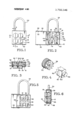
- FIG. 1 is a front elevation of a lock embodying the principles of the invention shown in the locked positron.
- FIG. 2 is a rear elevation with the back cover of the housing swung away and with parts removed for clarity.
- FIG. 3 is a section taken along the line 3-3 of FIG. 1.
- FIG. 4 is an exploded isometric of the typical dial and tumbler used with the lock of FIG. 1.
- FIG. 5 is a rear elevation similar to FIG. 2 showing the lock in an opened position.
- FIG. 6 is a section taken along the line 6-6 of FIG. 1.
- the lock includes a housing 10 having an integral top wall 12, sidewalls 14, bottom wall 16, and front wall 18.
- the top wall 12 is provided with a shackle opening 22 which receives the free end of a shackle 24.
- the housing is also provided with a back cover 26 also having a top wall 28 and a bottom wall 30.
- the top wall is provided with a second shackle opening 32.
- the back cover is pivotally mounted on the top and bottom walls 12 and 16 of the housing 10 and nests against the housing walls as best shown in FIG. 3.
- a retainer plate 36 Secured within the housing 10 is a retainer plate 36 having four spaced bores 37. Positioned on top of the retainer plate is a slider 38 having four bores 39 registrable with the bores 37. The bores 39 are interconnected by slots 40.
- the shackle 24 is received in a bore 42 for rotatable movement and is held for longitudinal movement relative to the slider by the pin 44 that nests in a groove 48 in the shackle. Thus, movement of the shackle longitudinally causes the slider to move along the same path.
- the front wall 18 of the housing is provided with four bores 50 which rotatably mount a plurality of dials 52.
- the dials are provided with pointers 53 which can be aligned with indexing marks 54 in a conventional manner.
- the dials are retained in the housing by clips 56.
- the inner surfaces of the dials are provided with segmented teeth 58.
- Rotatably positioned in the bores of the retainer plate 36 are four tumblers having teeth 62 engageable with the teeth 58 of the dials. As best shown in FIG. 3, the teeth of the respective dial and tumbler interengage one another so that relative anguiar movement when engaged is precluded and they move as a unit.
- the tumblers are provided with locking cams 64 having a thickness slightly less than the width of the slots 40 and offset from the centers of the tumblers.
- the tumblers terminate at their free ends in guide pins 66 that are retained in bores 67 in a spacer plate 68.
- the spacer plate retains the tumblers against lateral movement in the slider.
- alignment of the locking cams in the slots 40 will allow the slider to be moved toward the top wall 12 of the housing freeing the shackle from the bores 22 and 32 of the top wall and back cover top wall.
- the locking cams may be rotated in the bores 39 of the slider so that they are out of alignment with the slots 40 and preclude the slider from being slid upwardly to the open position. Since the cams 64 are offset, there is only one rotational position in which they are aligned with the slots40.
- the lock is opened and the back cover swung out of the way as in FIG. 2.
- the spacer plate 68 is removed, allowing access to the tumblers 60.
- the tumblers can then be lifted out of engagement with the teeth 58 of the dials and rotated relative to the dials into a new relative angular position.
- This change requires a different alignment between the pointer 53 and the index mark 54 for an internal alignment of the locking cam with the slot 40.
- a lock comprising a housing having a front wall provided with a plurality of first bores for holding a plurality of dials and a top wall having a shackle opening,
- slider means in said housing having a plurality of second bores registrable with said first bores in a locked operative position and movable along a path out of registry with said first bores into an opened operative position, said slider including slots interconnecting said second bores along said path of movement,
- tumblers interengaged with said dials and positioned in-said second bores, said tumblers having locking cams rotatable in said second bores and slidable through said slots when aligned therewith for opening the lock and impassable through said slots when non-aligned therewith for precluding opening of said lock.
Landscapes
- Lock And Its Accessories (AREA)
Abstract
A housing contains a slider having bores interconnected by slots and a shackle rotatably secured to the slider for movement therewith. Dials are interconnected with tumblers having locking cams rotatable in the bores and slidable in the slots. The tumblers may be disengaged and rotated relative to the dials for changing the combination. Registry of the locking cams with the slots allows movement of the slider to open the shackle.
Description
United States Patent 11 1 Jeh 1451 Sept. 4, 1973 LOCK [75] Inventor: Chi-Sun Jeh, Taipei, China [73] Assignee: Lee Ahroni, Seattle, Wash.
[22] Filed: Sept. 18, 1972 [21] Appl. No.: 290,247
[52] US. Cl. 70/25, 70/312 [51] Int. Cl EOSb 37/14 [58] Field of Search 70/25, 312, 26, 316, 70/24, 287, 288, 22
[56] References Cited UNITED STATES PATENTS 661,560 11 1900 Stall 70/26 1,352,771 9/1920 Vartuli 70/25 3,411,330 11/1968 Atkinson 70/312 X FOREIGN PATENTS OR APPLICATIONS 1,011,131 4/1952 France 70/25 Primary ExaminerRobert L. Wolfe Attorney-Richard W. Seed, Carl G. Dowrey et al.
[57] ABSTRACT A housing contains a slider having bores interconnected by slots and a shackle rotatably secured to the slider for movement therewith. Dials are interconnected with tumblers having locking cams rotatable in the bores and slidable in the slots. The tumblers may be disengaged and rotated relative to the dials for changing the combination. Registry of the locking cams with the slots allows movement of the slider to open the shackle.
5 Claims, 6 Drawing Figures LOCK SUMMARY OF THE INVENTION It is an object of this invention to provide an inexpensive combination lock.
It is another object of this invention to provide a combination lock having a readily changeable combination.
Basically the invention includes a housing holding slider means movable along a path in the housing. A shackle is rotatably mounted for movement with the slider with the shackles free end being engageable within a hole in the top wall of the housing as the slider is moved into a locking position. The slider means is provided with bores registrable' with bores in the front wall of the housing and interconnected along the path of movement by slots. Tumblers having locking cams are positioned within the bores of the slider means and can be rotated into alignment with the slots for allowing the slider means to move into the open position. Dials are provided in the front wall of the housing and the tumblers are engageable therewith so that the dials may rotate the tumblers with the tumblers being removable from the dials to change the combination.
BRIEF DESCRIPTION OF THE FIGURES OF THE DRAWINGS FIG. 1 is a front elevation of a lock embodying the principles of the invention shown in the locked positron.
FIG. 2 is a rear elevation with the back cover of the housing swung away and with parts removed for clarity.
FIG. 3 is a section taken along the line 3-3 of FIG. 1.
FIG. 4 is an exploded isometric of the typical dial and tumbler used with the lock of FIG. 1.
FIG. 5 is a rear elevation similar to FIG. 2 showing the lock in an opened position.
FIG. 6 is a section taken along the line 6-6 of FIG. 1.
DESCRIPTION OF THE PREFERRED EMBODIMENT As best shown in FIGS. 2 and 3, the lock includes a housing 10 having an integral top wall 12, sidewalls 14, bottom wall 16, and front wall 18. The top wall 12 is provided with a shackle opening 22 which receives the free end of a shackle 24. The housing is also provided with a back cover 26 also having a top wall 28 and a bottom wall 30. The top wall is provided with a second shackle opening 32. The back cover is pivotally mounted on the top and bottom walls 12 and 16 of the housing 10 and nests against the housing walls as best shown in FIG. 3.
Secured within the housing 10 is a retainer plate 36 having four spaced bores 37. Positioned on top of the retainer plate is a slider 38 having four bores 39 registrable with the bores 37. The bores 39 are interconnected by slots 40. The shackle 24 is received in a bore 42 for rotatable movement and is held for longitudinal movement relative to the slider by the pin 44 that nests in a groove 48 in the shackle. Thus, movement of the shackle longitudinally causes the slider to move along the same path.
The front wall 18 of the housing is provided with four bores 50 which rotatably mount a plurality of dials 52. The dials are provided with pointers 53 which can be aligned with indexing marks 54 in a conventional manner. The dials are retained in the housing by clips 56. The inner surfaces of the dials are provided with segmented teeth 58. Rotatably positioned in the bores of the retainer plate 36 are four tumblers having teeth 62 engageable with the teeth 58 of the dials. As best shown in FIG. 3, the teeth of the respective dial and tumbler interengage one another so that relative anguiar movement when engaged is precluded and they move as a unit. The tumblers are provided with locking cams 64 having a thickness slightly less than the width of the slots 40 and offset from the centers of the tumblers. The tumblers terminate at their free ends in guide pins 66 that are retained in bores 67 in a spacer plate 68. The spacer plate retains the tumblers against lateral movement in the slider. As is readily apparent, alignment of the locking cams in the slots 40 will allow the slider to be moved toward the top wall 12 of the housing freeing the shackle from the bores 22 and 32 of the top wall and back cover top wall. When the slider is in the locked position, the locking cams may be rotated in the bores 39 of the slider so that they are out of alignment with the slots 40 and preclude the slider from being slid upwardly to the open position. Since the cams 64 are offset, there is only one rotational position in which they are aligned with the slots40.
To change the combination the lock is opened and the back cover swung out of the way as in FIG. 2. Next, the spacer plate 68 is removed, allowing access to the tumblers 60. The tumblers can then be lifted out of engagement with the teeth 58 of the dials and rotated relative to the dials into a new relative angular position. This change, of course, requires a different alignment between the pointer 53 and the index mark 54 for an internal alignment of the locking cam with the slot 40.
While the preferred form of the invention has been illustrated and described, it should be understood that variations will be apparent to one skilled in the art without departing from the principlesof the invention. Accordingly, the invention is not to be limited to the embodiment herein, but only by a literal interpretation of the claims appended hereto.
The embodiments of the invention in which an exclusive property or privilege is claimed are defined as follows:
l. A lock comprising a housing having a front wall provided with a plurality of first bores for holding a plurality of dials and a top wall having a shackle opening,
slider means in said housing having a plurality of second bores registrable with said first bores in a locked operative position and movable along a path out of registry with said first bores into an opened operative position, said slider including slots interconnecting said second bores along said path of movement,
a shackle rotatably secured to said slider means and movable therewith and having a free end positionable in said shackle opening when said slider means is in said locked operative position, and
a plurality of tumblers interengaged with said dials and positioned in-said second bores, said tumblers having locking cams rotatable in said second bores and slidable through said slots when aligned therewith for opening the lock and impassable through said slots when non-aligned therewith for precluding opening of said lock.
tioned between said slider and said housing front wall, and a spacer plate positioned between said rear cover and said slider means, said tumblers having pivot pins, said spacer plate having bores alignable with said pivot pins to retain said tumblers against lateral movement.
5. Thelock of claim 1 said locking cams being radially offset from the centers of said tumblers and alignable with said slots in only a single rotational position of said tumblers.
l l I I
Claims (5)
1. A lock comprising a housing having a front wall provided with a plurality of first bores for holding a plurality of dials and a top wall having a shackle opening, slider means in said housing having a plurality of second bores registrable with said first bores in a locked operative position and movable along a path out of registry with said first bores into an opened operative position, said slider including slots interconnecting said second bores along said path of movement, a shackle rotatably secured to said slider means and movable therewith and having a free end positionable in said shackle opening when said slider means is in said locked operative position, and a plurality of tumblers interengaged with said dials and positioned in said second bores, said tumblers having locking cams rotatable in said second bores and slidable through said slots when aligned therewith for opening the lock and impassable through said slots when non-aligned therewith for precluding opening of said lock.
2. The lock of claim 1, said dials each having a toothed inner surface, said tumblers also each having a toothed inner surface interengaging with said dial inner surface for movement therewith but removable therefrom for allowing a change in the angular position of the tumblers with the dials for changing the unlocking combination of the lock.
3. The lock of claim 1, said housing including a pivotal rear cover for allowing access to said slider means.
4. The lock of claim 3 including a retainer plate positioned between said slider and said housing front wall, and a spacer plate positioned between said rear cover and said slider means, said tumblers having pivot pins, said spacer plate having bores alignable with said pivot pins to retain sAid tumblers against lateral movement.
5. The lock of claim 1 said locking cams being radially offset from the centers of said tumblers and alignable with said slots in only a single rotational position of said tumblers.
Applications Claiming Priority (1)
| Application Number | Priority Date | Filing Date | Title |
|---|---|---|---|
| US29024772A | 1972-09-18 | 1972-09-18 |
Publications (1)
| Publication Number | Publication Date |
|---|---|
| US3756046A true US3756046A (en) | 1973-09-04 |
Family
ID=23115140
Family Applications (1)
| Application Number | Title | Priority Date | Filing Date |
|---|---|---|---|
| US00290247A Expired - Lifetime US3756046A (en) | 1972-09-18 | 1972-09-18 | Lock |
Country Status (1)
| Country | Link |
|---|---|
| US (1) | US3756046A (en) |
Cited By (9)
| Publication number | Priority date | Publication date | Assignee | Title |
|---|---|---|---|---|
| US5870909A (en) * | 1997-09-08 | 1999-02-16 | Saunders, Jr.; Daniel H. | Tamper resistant lock |
| US6298694B1 (en) * | 1997-09-18 | 2001-10-09 | Knollan Ltd. | Combination lock mechanism |
| US20040035158A1 (en) * | 2002-08-26 | 2004-02-26 | Chun-Yuan Chang | Number lock device for computer |
| USD557107S1 (en) | 2004-11-08 | 2007-12-11 | Master Lock Company Llc | Lock |
| USD573871S1 (en) | 2008-01-11 | 2008-07-29 | Master Lock Company Llc | Lock |
| USD582251S1 (en) | 2007-06-01 | 2008-12-09 | Master Lock Company Llc | Lock |
| USD594731S1 (en) | 2008-10-10 | 2009-06-23 | Master Lock Company Llc | Lock |
| USD629280S1 (en) | 2008-10-10 | 2010-12-21 | Master Lock Company Llc | Lock |
| USD691870S1 (en) | 2012-06-04 | 2013-10-22 | Master Lock Company Llc | Lock |
Citations (4)
| Publication number | Priority date | Publication date | Assignee | Title |
|---|---|---|---|---|
| US661560A (en) * | 1900-08-20 | 1900-11-13 | Adam Newton Stall | Combination-lock. |
| US1352771A (en) * | 1920-05-22 | 1920-09-14 | Francis C Vartuli | Combination-lock |
| FR1011131A (en) * | 1948-12-13 | 1952-06-19 | Padlock | |
| US3411330A (en) * | 1967-07-31 | 1968-11-19 | Long Mfg Co Inc | Combined latch and lock structure |
-
1972
- 1972-09-18 US US00290247A patent/US3756046A/en not_active Expired - Lifetime
Patent Citations (4)
| Publication number | Priority date | Publication date | Assignee | Title |
|---|---|---|---|---|
| US661560A (en) * | 1900-08-20 | 1900-11-13 | Adam Newton Stall | Combination-lock. |
| US1352771A (en) * | 1920-05-22 | 1920-09-14 | Francis C Vartuli | Combination-lock |
| FR1011131A (en) * | 1948-12-13 | 1952-06-19 | Padlock | |
| US3411330A (en) * | 1967-07-31 | 1968-11-19 | Long Mfg Co Inc | Combined latch and lock structure |
Cited By (14)
| Publication number | Priority date | Publication date | Assignee | Title |
|---|---|---|---|---|
| US5870909A (en) * | 1997-09-08 | 1999-02-16 | Saunders, Jr.; Daniel H. | Tamper resistant lock |
| US6298694B1 (en) * | 1997-09-18 | 2001-10-09 | Knollan Ltd. | Combination lock mechanism |
| US20040035158A1 (en) * | 2002-08-26 | 2004-02-26 | Chun-Yuan Chang | Number lock device for computer |
| US6973809B2 (en) * | 2002-08-26 | 2005-12-13 | Chun-Yuan Chang | Number lock device for computer |
| USD557107S1 (en) | 2004-11-08 | 2007-12-11 | Master Lock Company Llc | Lock |
| USD582251S1 (en) | 2007-06-01 | 2008-12-09 | Master Lock Company Llc | Lock |
| USD573871S1 (en) | 2008-01-11 | 2008-07-29 | Master Lock Company Llc | Lock |
| USD583218S1 (en) | 2008-01-11 | 2008-12-23 | Master Lock Company Llc | Lock |
| USD594731S1 (en) | 2008-10-10 | 2009-06-23 | Master Lock Company Llc | Lock |
| USD629280S1 (en) | 2008-10-10 | 2010-12-21 | Master Lock Company Llc | Lock |
| USD638279S1 (en) | 2008-10-10 | 2011-05-24 | Master Lock Company Llc | Lock |
| USD691870S1 (en) | 2012-06-04 | 2013-10-22 | Master Lock Company Llc | Lock |
| USD704531S1 (en) | 2012-06-04 | 2014-05-13 | Master Lock Company Llc | Lock |
| USD729038S1 (en) | 2012-06-04 | 2015-05-12 | Master Lock Company Llc | Lock |
Similar Documents
| Publication | Publication Date | Title |
|---|---|---|
| US3756046A (en) | Lock | |
| US3702549A (en) | High security door lock | |
| US3469874A (en) | Coin vault door lock construction | |
| US3837189A (en) | Padlock construction | |
| HUP0001502A2 (en) | Programmable cylinder lock, provided with master keys | |
| US3630053A (en) | Safety lock | |
| GB1337374A (en) | Key operable padlock with key lock plug | |
| ES8202394A1 (en) | Lock | |
| US3738137A (en) | Doorknob locking device | |
| US2724257A (en) | Safety chain door retaining latch | |
| US3956912A (en) | Filing cabinet lock having plate tumbler-type plug assembly | |
| SU1097205A3 (en) | Cylinder lock with magnetic catches | |
| US3452563A (en) | Combination lock mechanism | |
| US1317092A (en) | Albert matjrer | |
| US5372022A (en) | Lock assembly | |
| GB737547A (en) | Cylinder lock | |
| GB1159737A (en) | A Pin Tumbler Lock Mechanism. | |
| US3858917A (en) | Device to prevent opening of a door or the like | |
| US2142610A (en) | Cylinder lock | |
| CN207048487U (en) | A sliding anti-theft tumbler lock that prevents unlocking tools from entering the unlocking area | |
| KR820000333B1 (en) | Surface mount combination lock | |
| US12129697B2 (en) | Long throw lock | |
| JPH07207997A (en) | Padlock | |
| JPH0619003Y2 (en) | Character alignment lock | |
| JPH11131874A (en) | Dial lock |