US374221A - Vania - Google Patents
Vania Download PDFInfo
- Publication number
- US374221A US374221A US374221DA US374221A US 374221 A US374221 A US 374221A US 374221D A US374221D A US 374221DA US 374221 A US374221 A US 374221A
- Authority
- US
- United States
- Prior art keywords
- pulley
- arm
- standard
- cord
- hand
- Prior art date
- Legal status (The legal status is an assumption and is not a legal conclusion. Google has not performed a legal analysis and makes no representation as to the accuracy of the status listed.)
- Expired - Lifetime
Links
- 241000382509 Vania Species 0.000 title description 4
- 210000001503 Joints Anatomy 0.000 description 8
- 241001125879 Gobio Species 0.000 description 2
- 241001125877 Gobio gobio Species 0.000 description 2
- 230000001154 acute Effects 0.000 description 2
- 230000000694 effects Effects 0.000 description 2
- 238000004804 winding Methods 0.000 description 2
Images

Classifications
-
- A—HUMAN NECESSITIES
- A61—MEDICAL OR VETERINARY SCIENCE; HYGIENE
- A61C—DENTISTRY; APPARATUS OR METHODS FOR ORAL OR DENTAL HYGIENE
- A61C1/00—Dental machines for boring or cutting ; General features of dental machines or apparatus, e.g. hand-piece design
- A61C1/0007—Control devices or systems
Definitions
- Dental engines have heretofore been made with a fly-wheel actuated by a treadle and a vertical standard, to the upper end of which a jointed arm is connected, with a hand-piece ro and drill or other tool at the end of the outer section of the arm, and an endless cord or belt has passed around the driving-wheel or flywheel and over pulleys at the joints between the standard and the arm, and also over pu1- I 5 leys between the sections of the arm and of the hand-piece.
- My inprovement relates to the conbination, 0 with the standard and the arm that is jointed thereto, of pulleys over which the endless cord is passed, the axis of the pulleys coinciding with the center of the joint, and the endless cordpassing over one pulley in one direc- 3 5 tion and the otherpulley in the opposite direction, so that when the arm is raised or lowered in relation to the standard one part of the endless cord is wound upon the pulley to eX- actly'the same eXtent that the other part of 0 the endless eord is wound off the pulley.
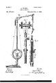
- Figure 1 is a general elevation of the dental engine.
- Fig. 2 is an elevation of the top of the standard and a part of the arni that is jointed thereto.
- Fig. 3 is an elevaton of the same at right angles to Fig. 2, the weight and cord being removed.
- Fg. 4 is a sectional elevation of the pinion and movable portion of the standard.
- Fig. 5 is an elevation of the cap over the pinion upon the standard.
- Fig. 6 is a side View of the joint between the two sections of the arm.
- Fig. 7 is an elevation of the same endwise of the arm.
- Fig. 8 is a side View of the paris of the junction of the hand-piece with thearn.
- Fig. 9 is an elevation of the parts endwise of the handpiece, and
- Fig. 10 is a detaehed View of the 6 slotted standard carrying the ilywheel in larger size than Fig. l.
- the base A is usually triangular, and froni the middle thereof the standard B rises, and it is adapted to receive the fiy-wheel O and its crank-shaft D, as usual, and the treadle E and connecting-rod F are used to drive the fly-wheel.
- the tubular standard G rises above the standard B, and the arm is made of two parts, H and K, that arejointed together, and the part H is united by a joint to the top end of the standard G, and the hand-pieceL is j ointed to the end of the section K.
- the hand-piece L is to be of any desired character, and the central shaft thereof operates a plugger, a drill, an anglepiece, or any other tool to which the handpiece is adapted.
- the belt N is endless and of any desired material, and it is to be passed around the fly-wheel and over the pulleys to the hand-piece; but it is advantageous to be able to take the belt off or put the sane on with facility without cutting or opening the endless belt N.
- the section may be swung open by removing one of the pins.
- an axial rod or tube, 4, that may be moved endwise to raise or lower the joint 6, that connccts the arm H; and I make use of the pinion 3, that is upon a horizontal shaft, 9, with a thumb-wheel, 10, at the end, by which the pinion is revolved to raise or lower the rod 4.
- a block upon the s'ide'of the standard G with a cap, ll, Secured by screws, so that the necessary friction can be obtained to prevent the pinion turning by tlje weight that is supported by it.
- Thejoint-pin 20 ot' the joint 6 is preferably extended to form the shai't or gudgeon for the pulleys 21 22, that are grooved for the endless cord to pass around.
- the endless cord passes simply up over the pulley 21; but in order to pass in the opposite direction around the pulley 22 it is wound almost around the same, as seen in Fig. 2.
- the arm H can be swung up or down without tightening or loosening the cord or band, because it will be wound upon the pulley 22 to exactly the same extent as it is unwound off the pulley 21, or vice versa.
- the ly-wheel will be slightly turned as the cord gives down on one side and is drawn up on the other side.
- the cord orbelt is not tightened or loosened by the movement of the arm H up or down.
- the joint-pin 27 becomes the shaft for the pulleys 28 and 29, and the cord goes above one pulley and below the other pulley, so as to act in the same manner as has been described with reference to the pulleys 21 22; but to lessen wear upon the band that would result from the rubbing of one part of the band against the other in passing entirely around the pulley 29, I prefer to lead the band or cord over the idler-pulley 30, and thence down over and beneath the pulley 29, the action of the parts being identically the same, and the object of the idler 30 being only to prevent or lessen wear upon the band or cord.
- an idler-pulley might be used in connection with the pulley 22, to prevent the rubbing of one part of the band against the other at the place where it crosses.
- This idler is indieated by dotted lines in Fig. 2. In each instance the idler is supported by an arm or branch extending out from the arm H.
- a pulley, 32 At the rear end of the hand-piece is a pulley, 32, around which the endless band passes, and by which motion is givcn to the drill or other instrument at the end of the hand piece, as usual; and the pivot-pin of the hinge that unites the arm K to the hand-piece is in line with or eXtended to form the shaft or gudgeons for the pulleys 33 and 34, and the cord or band passes at one side ot' the pulley 33 and at the other side of the pulley 34, in order that the band may not be slackened or tightened by the swinging ot' the hand-piece upon the joint by which it is connected to the arm K; and in order to guide the belt in passing around the pulley 32,I make use of the guidepulleys 35 and 36, that are placed almost in contact with the respective pulleys 33 and 34, and in such positions that the band will be properly guided to the pu1ley32, the distance between the respective pulleys 33 and
- a seetor, 40 passing through a mortise in the upper part of the standard and extending sufficiently to the rear for receiving the eounterpoise 41, by which the weight of the arm H and the parts connected therewith are balanced; and it is preferable to have the weight suffioiently heavy to cause the outer end of the arm H to rise when not otherwise acted upon, as this facilitates the use of the hand-piece.
- the clamping-screw 43 is employed for holding the. seetor and the arm H at a fixed angle to the standard whenever so desired.
Description
(No Model.) 2 sheets-Sheet -1.
A. WEBE-R. I
DENTAL ENGINE.
No. 374,221-. Patented Dec'. 6, 1887.
2 Sheets--Sheet' 2.
(No Model.)
A. WEBER. DENTAL BNGINB.,
`N0. 374,221. Patented Dec. 6,188?.
N, PETERs. Faa-Lilhn r her, washington, D. c.
UNITED STATES PATENT OFFICE.
AUGUST WEBER, OF NEW YORK, N. Y., ASSIGNOR TO THE S. S. VVHITE DENTAL MANUFAOTURING COMPANY, OF PHILADELPHIA, PENNSYL- VANIA SPECIFICATION forming part of Letters Patent No. 374221, dated December 6,188?.
To aZZ whom, it may con/067%:
Be it known that I, AUGUST VVEBER, of the city and State of New York, have invented an Improvement in Dental Engines, of which the following is a specificaton.
Dental engines have heretofore been made with a fly-wheel actuated by a treadle and a vertical standard, to the upper end of which a jointed arm is connected, with a hand-piece ro and drill or other tool at the end of the outer section of the arm, and an endless cord or belt has passed around the driving-wheel or flywheel and over pulleys at the joints between the standard and the arm, and also over pu1- I 5 leys between the sections of the arm and of the hand-piece.
In consequence of the motion given to the hand-piece in properly placing it for operation, the belt is liable to become slack or too tightly strained. Efforts have been made to,
compensate this difference in the tension of the belt by placing the joints between the respective paris of the arm at a distance from the aXis of the pulleys; but this is not accurate 2 5 in its operation, because in certain positions the belt will be wound farther upon the pulley than in other positions,and the uniformity of tension will not be maintained.
My inprovementrelates to the conbination, 0 with the standard and the arm that is jointed thereto, of pulleys over which the endless cord is passed, the axis of the pulleys coinciding with the center of the joint, and the endless cordpassing over one pulley in one direc- 3 5 tion and the otherpulley in the opposite direction, so that when the arm is raised or lowered in relation to the standard one part of the endless cord is wound upon the pulley to eX- actly'the same eXtent that the other part of 0 the endless eord is wound off the pulley. Thereby the absolute uniformity of tension is maintained; and with the joint in the arm and with the joint between the arni and the hand piece idler-pulleys are made use of, so as to allow for the endless cord or band passing,` in the opposite direction,for the purposes before mentioned; and I make use of a standard that is provided with an adjustment for tightening the cord to whatever eXtent may be desired.
In the drawings,Figure 1 is a general elevation of the dental engine. Fig. 2 is an elevation of the top of the standard and a part of the arni that is jointed thereto. Fig. 3 is an elevaton of the same at right angles to Fig. 2, the weight and cord being removed. Fg. 4 is a sectional elevation of the pinion and movable portion of the standard. Fig. 5 is an elevation of the cap over the pinion upon the standard. Fig. 6 is a side View of the joint between the two sections of the arm. Fig. 7 is an elevation of the same endwise of the arm. Fig. 8 is a side View of the paris of the junction of the hand-piece with thearn. Fig. 9 is an elevation of the parts endwise of the handpiece, and Fig. 10 is a detaehed View of the 6 slotted standard carrying the ilywheel in larger size than Fig. l.
The base A is usually triangular, and froni the middle thereof the standard B rises, and it is adapted to receive the fiy-wheel O and its crank-shaft D, as usual, and the treadle E and connecting-rod F are used to drive the fly-wheel. The tubular standard G rises above the standard B, and the arm is made of two parts, H and K, that arejointed together, and the part H is united by a joint to the top end of the standard G, and the hand-pieceL is j ointed to the end of the section K. These parts are of the general character heretofore in use, except in the particulars hereinafter named, So and I remark that the hand-piece L is to be of any desired character, and the central shaft thereof operates a plugger, a drill, an anglepiece, or any other tool to which the handpiece is adapted. y The belt N is endless and of any desired material, and it is to be passed around the fly-wheel and over the pulleys to the hand-piece; but it is advantageous to be able to take the belt off or put the sane on with facility without cutting or opening the endless belt N. To provide for so doing, I make the standard B with a removable section, 2, at one side of the fly-wheel, and at the ends of this section there are lugs that receive through them the cross-plus 3, so that 5 when in place this section closes the opening that there would otherwise be in one side of the twopart standard or inelosing-frame, and the two sides of the standard are rendered uniform, or nearly so, in strength; but when IOO the pins 3 are pulled out the section 2 can be removed and the endless belt removed or inserted so as to pass properly around the flywheel. The section may be swung open by removing one of the pins.
At the top of the tubular standard G there is received an axial rod or tube, 4, that may be moved endwise to raise or lower the joint 6, that connccts the arm H; and I make use of the pinion 3, that is upon a horizontal shaft, 9, with a thumb-wheel, 10, at the end, by which the pinion is revolved to raise or lower the rod 4. There is a block upon the s'ide'of the standard G, with a cap, ll, Secured by screws, so that the necessary friction can be obtained to prevent the pinion turning by tlje weight that is supported by it.
The teeth of the pinion gear into teeth upon the rod 4, and I prefer to make these teeth by a screw-thread cut into the surface of said rod 4, so that the raek will not be liable to wear out, and the rod can be revolved, as the arm H is swung, without the teeth becoming separated from the teeth of the pinion; and in addition to this the standard can be lengthened or shortened by rotating the rod 4 and its screw-thread teeth, the pinion in that case forming a nut for the same. I prefer to make this rod 4 in two parts, as seen in Figs. 2 and 3, one part being tubular to receive the other part, there being bearing- disks 14 and 15 upon the respective parts, so that lubrieating material can be introduced between these bearingdisks to allow the arm H to swing, when in use, with but little friction. Thejoint-pin 20 ot' the joint 6 is preferably extended to form the shai't or gudgeon for the pulleys 21 22, that are grooved for the endless cord to pass around. The endless cord passes simply up over the pulley 21; but in order to pass in the opposite direction around the pulley 22 it is wound almost around the same, as seen in Fig. 2. It will now be evident that if, for illustration,
,the endless cord were tied fast to the arm H,
where it passes along at the sides thereof and the cord properly tightened by the pinion 8, the arm H can be swung up or down without tightening or loosening the cord or band, because it will be wound upon the pulley 22 to exactly the same extent as it is unwound off the pulley 21, or vice versa. The ly-wheel, however, will be slightly turned as the cord gives down on one side and is drawn up on the other side. Of course the same effect takes place when the engine is running-that is to say, the cord orbeltis not tightened or loosened by the movement of the arm H up or down. At the joint 26 between the arm-sections H and Kthe joint-pin 27 becomes the shaft for the pulleys 28 and 29, and the cord goes above one pulley and below the other pulley, so as to act in the same manner as has been described with reference to the pulleys 21 22; but to lessen wear upon the band that would result from the rubbing of one part of the band against the other in passing entirely around the pulley 29, I prefer to lead the band or cord over the idler-pulley 30, and thence down over and beneath the pulley 29, the action of the parts being identically the same, and the object of the idler 30 being only to prevent or lessen wear upon the band or cord.
It will be evident that an idler-pulley might be used in connection with the pulley 22, to prevent the rubbing of one part of the band against the other at the place where it crosses. This idler is indieated by dotted lines in Fig. 2. In each instance the idler is supported by an arm or branch extending out from the arm H.
At the rear end of the hand-piece is a pulley, 32, around which the endless band passes, and by which motion is givcn to the drill or other instrument at the end of the hand piece, as usual; and the pivot-pin of the hinge that unites the arm K to the hand-piece is in line with or eXtended to form the shaft or gudgeons for the pulleys 33 and 34, and the cord or band passes at one side ot' the pulley 33 and at the other side of the pulley 34, in order that the band may not be slackened or tightened by the swinging ot' the hand-piece upon the joint by which it is connected to the arm K; and in order to guide the belt in passing around the pulley 32,I make use of the guidepulleys 35 and 36, that are placed almost in contact with the respective pulleys 33 and 34, and in such positions that the band will be properly guided to the pu1ley32, the distance between the respective pulleys 33 and 35 and 34 and 36 being only suflicient for slipping in the cord or band. It will now be apparent that when the hand-piece is moved to an acute angle with the arm K the cord or band will be wound farther upon the pulley 33, and it will be unwound from the pulley 34 to the same extent, and if the movement toward the arm K be continued the cord will leave the pulley 34 and bear only upon the pulley 33, and on the other hand, if the hand-piece assumes an obtuse angle to the arm K, the cord will be i wound more upon the pulley 34 and partially unwound from the pulley 33, and by the further movement will leave the pulley 33 and be further wound around the pulley 34. In any nstance,the winding and unwinding being in the opposite direction on one side from what it is on the other side, the, cord or band will not be tightened or slackened, but will be maintained at a uniform tension.
It is usual to connect the hand-piece by a swivel with the arm H, so that the hand-piece may be partially rotated upon the swivel as said hand-piece is turned in the necessary direction for Operating the tool. This, however, does not materially interfere with the tension of the cord or band, because the angle that the cord or band assumes in relation to the arm H is but slight.
Below the arm H and connected with the same is a seetor, 40, passing through a mortise in the upper part of the standard and extending sufficiently to the rear for receiving the eounterpoise 41, by which the weight of the arm H and the parts connected therewith are balanced; and it is preferable to have the weight suffioiently heavy to cause the outer end of the arm H to rise when not otherwise acted upon, as this facilitates the use of the hand-piece. The clamping-screw 43 is employed for holding the. seetor and the arm H at a fixed angle to the standard whenever so desired.
It will be observed that I have shown the driving belt or c'ord wound about one of the coincident pulleys at the top of the standard, in order to gain the effeot of the third idler or guide pulley shown at the other joints, there- 'fore vi-tually making one ofthe belt-pulley the third pulley or guide also for the belt or cord, and they are equivalents with the belt so wound. The third or idler pulley is simply a guide for the belt or oord to keep it in proper relation to the coincident pulleys.
I claim as my inventionl. The forked standard or inclosing-frame fitted with bearings for the pulley thereofiand having a removable section and seouring device therefor,substantial1y as described, whereby the endless eord may be inserted in the groove of said inclosed pulley and readily removed while the pulley is inolosed in operation, as before set forth.
2. The oombination, with the tubular standard of a dental engine and the extension rod or section thereof having teeth or threads thereon, of the pinion-wheel mounted on said standard and engaging said teeth to raise and lower said eXtension-rod, and the Operatingshaft of said pi nion,substa'ntial1v as described.
3. In a belt-eompensating device, the combination of two j ointed arms and two pulleys, the axes ot' which are coincidcnt with the jonts of said arms, and a third belt pulley or guide, substantially as described.
4:. The combination of the engine standard, the jointed arms thereof, the pulleys coincident with the joints of said arms, and the endless driving belt or cord passing over one and under the other of the eoiucident pulleys,snbstantially as described.
5. The combination, with the enginestandard and the lateral arm H, joiuted to said standard, of the segment of said lateral arn and the counterpoise of said segment, substantially as described;
Signed by me this 4th day of October, 1886.
AUGUST WEBER.
Witnesses:
GEO. T. PINOKNEY, WILLIAM G. MOTT.
Publications (1)
| Publication Number | Publication Date |
|---|---|
| US374221A true US374221A (en) | 1887-12-06 |
Family
ID=2443231
Family Applications (1)
| Application Number | Title | Priority Date | Filing Date |
|---|---|---|---|
| US374221D Expired - Lifetime US374221A (en) | Vania |
Country Status (1)
| Country | Link |
|---|---|
| US (1) | US374221A (en) |
-
0
- US US374221D patent/US374221A/en not_active Expired - Lifetime
Similar Documents
| Publication | Publication Date | Title |
|---|---|---|
| US401677A (en) | Belt-tightener for planing-machines | |
| US374221A (en) | Vania | |
| US151256A (en) | Geoege walkee | |
| US420692A (en) | Drill-operating device | |
| US476944A (en) | Dental engine | |
| US460699A (en) | Ernst f | |
| US454242A (en) | Dental engine | |
| US96937A (en) | Improvement in hand-spinning machines | |
| US491099A (en) | Dental engine | |
| US1091964A (en) | Fence-stretcher. | |
| US612590A (en) | Dental engine | |
| US344531A (en) | Steering device for tricycles | |
| US328377A (en) | William f | |
| US25489A (en) | clark | |
| US399339A (en) | Isaac p | |
| US561561A (en) | Dental engine | |
| USRE6921E (en) | Improvement in apparatus for transmitting power | |
| US658380A (en) | Carving-machine. | |
| US205916A (en) | Improvement in belt-tighteners | |
| US1180063A (en) | Belt-shifter. | |
| US799613A (en) | Motor attachment for linotype-machines. | |
| US217192A (en) | John p | |
| US755031A (en) | Polishing and buffing machine. | |
| US206650A (en) | Improvement in devices for shearing animals | |
| US427425A (en) | Charles w |