US3739754A - Rotating-piston toroidal machine with rotating-disc abutment - Google Patents
Rotating-piston toroidal machine with rotating-disc abutment Download PDFInfo
- Publication number
- US3739754A US3739754A US00094690A US3739754DA US3739754A US 3739754 A US3739754 A US 3739754A US 00094690 A US00094690 A US 00094690A US 3739754D A US3739754D A US 3739754DA US 3739754 A US3739754 A US 3739754A
- Authority
- US
- United States
- Prior art keywords
- chamber
- piston
- machine
- abutment
- axis
- Prior art date
- Legal status (The legal status is an assumption and is not a legal conclusion. Google has not performed a legal analysis and makes no representation as to the accuracy of the status listed.)
- Expired - Lifetime
Links
- 238000002485 combustion reaction Methods 0.000 claims abstract description 14
- 230000006835 compression Effects 0.000 claims abstract description 11
- 238000007906 compression Methods 0.000 claims abstract description 11
- 238000005192 partition Methods 0.000 claims description 24
- 230000013011 mating Effects 0.000 claims description 13
- 238000010408 sweeping Methods 0.000 claims description 13
- 230000000295 complement effect Effects 0.000 claims description 10
- 238000004891 communication Methods 0.000 claims description 8
- 230000002000 scavenging effect Effects 0.000 claims description 6
- 239000007789 gas Substances 0.000 claims description 4
- 238000009877 rendering Methods 0.000 claims description 4
- 239000000567 combustion gas Substances 0.000 claims description 2
- 230000008878 coupling Effects 0.000 claims description 2
- 238000010168 coupling process Methods 0.000 claims description 2
- 238000005859 coupling reaction Methods 0.000 claims description 2
- 239000012530 fluid Substances 0.000 abstract description 5
- 230000002093 peripheral effect Effects 0.000 description 4
- 239000000446 fuel Substances 0.000 description 2
- 238000013459 approach Methods 0.000 description 1
- 230000005465 channeling Effects 0.000 description 1
- 239000002360 explosive Substances 0.000 description 1
- 238000010304 firing Methods 0.000 description 1
- 238000007789 sealing Methods 0.000 description 1
Images


Classifications
-
- F—MECHANICAL ENGINEERING; LIGHTING; HEATING; WEAPONS; BLASTING
- F01—MACHINES OR ENGINES IN GENERAL; ENGINE PLANTS IN GENERAL; STEAM ENGINES
- F01C—ROTARY-PISTON OR OSCILLATING-PISTON MACHINES OR ENGINES
- F01C3/00—Rotary-piston machines or engines with non-parallel axes of movement of co-operating members
- F01C3/02—Rotary-piston machines or engines with non-parallel axes of movement of co-operating members the axes being arranged at an angle of 90 degrees
Definitions
- ABSTRACT Fluid-handling machines having toroidal chambers and one or more rotating pistons, the chambers being divided into compartments by one or more rotating disc abutments provided with notches for passage of the pistons. Multiple chambers may employ common abutments, and plural abutments may be employed with one or more chambers. Matched chamber, piston, and abutment contours provide high-pressure fluid seals. Central distributor tubes are employed, which may be shifted axially to reverse the direction of rotation of the pistons, and the distributor tube may have a central compression/combustion niche adapted to communicate with the toroidal chamber.
- This invention relates to rotating-piston fluidhandling machines suitable for energy converting devices, such as steam engines, hot air engines, internal combustion engines, hydraulic motors, pumps, torque converters, or compressors. More specifically, the invention is concerned with rotating piston machines of the type having toroidal chambers and rotating disc abutments.
- Prior fluid-handling machines have employed pistons rotating in an annular chamber and operating in conjunction with disc abutments which project into the chamber so as to divide it into compartments at opposite sides of the rotating piston.
- the abutments are provided with peripheral notches which are rotatedinto the chamber at the appropriate time to permit passage of the rotating piston.
- the abutments may rotate about an axis parallel to the axis of piston rotation, or they may rotate about an axis transverse to the rotational axis of the piston.
- a vexing problem in this type of machine is the difficulty of providing high-pressure tightness between the rotating parts. Small and oddlyshaped pistons and abutment notches are usually employed to minimize the problem. The attainment of high thermal and mechanical efficiency is not possible in this type of machine.
- Another object of the invention is to provide an improved machine of the foregoing type which permits high compression ratios and the consequent attainment of high thermal and mechanical efficiencies.
- Still another object of the invention is to provide an improved intake and exhaust arrangement, with uniflow (non-reversing) streaming of the working fluid.
- Another object of the invention is to provide an improved arrangement for reversing the direction of rotation of the pistons.
- a further object of the invention is to provide unique multiple-chamber and multiple-abutment machines.
- Yet another object of the invention is to provide a multiple-abutment machine incorporating pressuremaintaining compartments.
- An additional object of the invention is to provide a unique internal combustion machine with a central compression/combustion niche.
- the machines of the present invention employ a toroidal chamber defined by inner and outer chamber members, the inner member having a piston which rotates through the chamber and which has a convex surface sweeping a concave surface of the outer member.
- a disc abutment rotates through the chamber about an axis transverse to the rotational axis of the piston and is provided with a notch for passage of the piston. Chambers may be provided at opposite sides of the disc abutment, and a pair of disc abutments may be provided at opposite sides of a single chamber. Disc abutments rotatable about the same axis and spaced apart along the axis may also be employed.
- Central distributor tubes are provided and may be shifted axially to reverse the direction of rotation of the pistons.
- the central distributor tube may also be provided with a compression/combustion niche in an internal combustion engine version of the invention.
- FIG. 1 is a transverse sectional view illustrating a dual-chamber machine of the invention
- FIG. 2 is a longitudinal sectional view taken approximately along line 22 of FIG. 1;
- FIG. 3 is a plan view of a distributor tube employed in the invention.
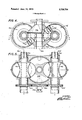
- FIG. 4 is a transverse sectional view of a dualchamber, dual-abutment embodiment of the invention.
- FIG. 5 is a longitudinal sectional view taken approximately along line 5-5 of FIG. 4;
- FIG. 6 is a transverse sectional view of a singlechamber, multiple-piston, dual-abutment embodiment of the invention.
- FIG. 7 is a longitudinal sectional view taken approximately along line 77 of FIG. 6;
- FIG. 8 is a longitudinal sectional view taken approximately along line 8-8 of FIG. 6;
- FIG. 9 is a transverse sectional view taken approximately along line 9-9 of FIG. 7 and illustrating output gearing.
- a machine of the invention comprises one or more toroidal stator chambers such as the chambers l0, 10'. While the embodiment of FIGS. 1 and 2 employs a pair of such chambers, it will be apparent that a single chamber or more than two chambers may be employed. Since the apparatus of FIGS. 1 and 2 is a dualmachine, a description of the left-hand portion will suffice for both.
- the toroidal chamber 10 is defined between an outer member 12 and an inner member 14. As seen in an axial plane (FIG. 2), the outer member is inwardly concave and the inner member is outwardly concave with respect to the axis of the chamber.
- the cross-section of the chamber shown is generally oval, although a circular cross-section may be employed, for example.
- the inner member 14 is a rotor and has an outwardly projecting segmental piston 16 fixed thereto.
- the piston is preferably of spherical-sectorial or ellipsoidal-sectorial form and has a convex outer surface which mates with and sweeps the concave surface of the outer chamber member 12.
- Piston rings (such as 18') are provided on the surface of the piston to ensure fluid-tight contact between the piston and the chamber wall.
- the outer chamber member 12 is part of or fixed to a block or frame 20 upon which the inner member 14 is supported rotatably by means of journals 22 and 24 in bores 26 and 28, the rotor 14 being held against axial movement by its rims 30 and 32.
- a disc abutment 34 is fixed to a shaft 36 rotatably supported upon the block 20 by means of bearings 38.
- the disc abutment is generally bi-conical, with the cones joined at their bases and the conical surfaces radial to the toroidal axis.
- the abutment 34 extends into the toroidal chamber 10 through an appropriately shaped opening in the chamber wall (which seals with the abutment surface) and has an edge surface 40 shaped to conform to the outer surface of the rotor 14 and provided with sealing rings 42 for a fluid-tight sliding fit with the rotor.
- a pair of compartments is formed in the toroidal chamber bounded by the abutment and the piston 16.
- the disc abutment is provided with a peripheral notch 44 having a helicoidal edge.
- the notch conforms generally to the concave configuration of the chamber member 12 and is large enough to allow passage of the piston 16 at an appropriate time during rotation of the piston in the chamber.
- the abutment 34 is driven synchronously with the output shaft 46 of the machine by a suitable gear train, one of the gears being shown at 48 in FIG. 1, so that the notch 44 arrives at the proper position to pass the piston 16 at the moment that the piston approaches the disc abutment, and then the chamber is blocked again by the abutment.
- the speed of rotation of the abutment may vary during its cycle to provide quick opening and closing of the toroidal chamber.
- the pitch of the helicoidal notch edge will be determined by the relative speeds of the piston and the abutment.
- the rotor 14 is coupled to the output shaft 46 by means of gears 50 and 52. It will be observed that the rotors of both parts of the dual-machine drive the same output shaft.
- a distributor tube 54 is provided centrally of the rotor 14 and is coaxial with the rotor and the toroidal chamber 10.
- the distributor tube has a transverse partition 56 dividing the tube into an intake passage 58 and an exhaust passage 60.
- a peripheral port 62 is provided at one side of the partition 56 and a circumferential series of slits 64 is provided at the opposite side of the partition.
- Ports 66 and 68 extend through the wall of the rotor 14 at opposite sides of the base of the piston 16 and at one side of the partition 56, and similar ports 70 and 72 are provided at opposite sides of the piston 16 and at the other side of the partition 56.
- Intake port 62 of the distributor tube 54 may be aligned selectively with one of ports 66 and 68, and exhaust slits 64 may be aligned selectively with one of ports 70 and 72, depending upon the axial position of the distributor tube, thereby to select the direction of rotation of the rotor 14.
- the distributor tube may be shifted axially by means of cooperating external threads 74 at one end of the distributor tube and internal threads of a worm wheel 76 which surrounds that end of the distributor tube and is rotatable within a cup 78.
- a longitudinal groove 80 of the distributor tube receives a pin not shown fixed to the inner surface of the cup 78 to prevent rotation of the distributor tube.
- a worm gear driven by a crank corresponding to elements 82' and 84 extends through an opening in cup 78 to engage the worm wheel 76 for adjusting the longitudinal position of the distributor tube.
- the abutments are spaced apart axially of the shaft 36a and are generally conical, but with the bases recessed and the side walls tapered in cross-section as shown in FIG. 4.
- the abutments extend through appropriately shaped openings in the toroidal chambers a and 10a and are provided with appropriately contoured edge surfaces which mate with and sweep the surfaces of the rotors in the manner previously described.
- the notches of the abutments are staggered so that when one abutment has its notch aligned with a toroidal chamber so as to pass a piston, the other abutment blocks that chamber.
- FIGS. 6 9 illustrate an embodiment of the invention employing a pair of abutments 34b and 34b of the type utilized in FIG. 1, but in conjunction with a single toroidal chamber 10b having a rotor 14b provided with a pair of pistons 16b and 16b projecting diametrically outward from the rotor.
- the notches 44b and 44b permit the passage of a piston at every half revolution of the rotor, the helicoidal edges of the notches having a pitch depending upon the speed of the pistons.
- the abutment discs are rotated by their shafts 36b and 36b, which are coupled by eccentric gearing 50b 52b and 50b 52b to worm wheels 86 and 88 driven from a worm gear 90 on the output shaft 46b.
- the eccentric gearing provides quick opening and shutting of the chamber 10b, so that the chamber will remain closed most of the time.
- piston 16b draws in air between its trailing face and abutment 34b after piston 16b passes inlet port 94, and it compresses air between its leading face and abutment 34b, the air having previously been sucked into this space by piston 16b.
- Each piston has a port 96 or 98 through the wall of the rotor adjacent to the leading face of the piston and adapted to mate with a peripheral port 100 in a fixed tube 102 and a similar port 104 in distributor tube 54b to permit air ahead of the leading face of the piston to be compressed into a compression/combustion niche 106 located in the transverse partition of the distributor tube.
- fuel or an explosive medium is injected into the niche 106 by a fuel injector 108, and the exploding gases expand out of the niche into the compartment behind that piston through mating ports 110 and 112 in tubes 54b and 102 and port 114 or 116 behind the piston.
- Compression ports 96 and 98 are off-set laterally from firing ports 114 and 116 so that they cooperate uniquely with the niche 106. Ignition occurs at every half revolution.
- the central distributor tube 54b has an inlet pipe 1 18 through which scavenging air is admitted from a suitable pressurized air supply. The air passes through ports 120 and 122 in the central tubes 54b and 102 to one of the ports 124 and 126 through the rotor at the trailing face of piston 16b or 16b (ports 124 and 126 being spaced laterally from ports 116 and 114, respectively).
- the scavenging air passes through port 124 or port 126 as the associated piston passes the abutment 34b, through the notch in abutment 34b, and out of exhaust port 9-2. If it is desired to reverse the rotation, the distributor tube may be shifted axially as before and it is necessary to provide additional ports. Ignition timing may be controlled by a cam inside the distributor tube, gearing 128 being provided for this purpose.
- a rotary piston machine comprising inner and outer complementary members of arcuate crosssection defining a toroidal chamber therebetween, the inner member being rotatable about the axis of the chamber and being substantially entirely outwardly concave relative to the axis in axial planes, the outer member being substantially entirely inwardly concave relative to the axis in axial planes, the inner member having a piston fixed thereto projecting into thetoroidal chamber with a convex surface mating with the concave surface of the outer member and sweeping the same, and a disc abutment rotatable about an axis transverse to the axis of said chamber and extending into said chamber through an opening therein, said abutment having an edge surface mating with the surface of the inner member and sweeping the same, said abutment having a helicoidal notch shaped to permit said piston to pass through said notch as the notch is rotated into said chamber.
- a machine in accordance with claim 1 further comprising a distributor tube extending through the inner member of said chamber and divided by atransverse partition, and means for providing communication between said tube and said chamber at opposite sides of said partition and opposite sides of said piston.
- a machine in accordance with claim 2 there being a pair of means at each side of said partition for providing communication between said tube and opposite sides of saidpiston, and means for rendering one of the communication-providing means at each side of the partition operative selectively.
- said means for rendering said communication-providing means operative selectively comprising means for moving said distributor tube longitudinally.
- a machine in accordance with claim 2 further comprising a compression/combustion niche centrally of said chamber, and means for providing communication between said niche and said chamber at predetermined times.
- a machine in accordance with claim 1 said inner member having a pair of pistons extending from oppo- 7.
- a rotary piston machine comprising a first pair of inner and outer complementary members defining a toroidal chamber therebetween, a second pair of inner and outer complementary members defining a toroidal chamber therebetween, each inner member being rotatable about the axis of its chamber and having a piston fixed thereto projecting into its chamber with a surface mating with the surface of the outer member and sweeping the same, the chamber axes being spaced apart and parallel, and a disc abutment rotatable about an axis between and transverse to a plane containing the axes of said chambers and extending into said chambers through openings therein, said abutment having an edge surface mating with the surfaces of the inner members and sweeping the same and having a notch to permit the pistons to pass therethrough when the notch is rotated into the associated chambers.
- outer members have entirely inwardly concave cross sections facing the axes of the associated chambers and said inner members have entirely outwardly concave cross sections complementary to the cross sections of said outer members.
- a rotary piston machine comprising inner and outer complementary members defining a toroidal chamber therebetween, the inner member being rotatable about the axis of the chamber and having a piston fixed thereto projecting into the chamber with a surface mating with the surface of the outer member and sweeping the same, and a pair of spaced disc abutments rotatable about a common axis transverse to the axis of said chamber and spaced from said chamber axis, said abutments extending into said chamber through corresponding openings therein,'said abutments having edge surfaces mating with the. surface of the inner member and sweeping the same, said abutments having notches permitting said piston to pass therethrough when the notches are in said chamber.
- said inner and outer members being of arcuate crosssection, the outer member being entirely inwardly concave relative to the axis of the chamber, the inner member being entirely outwardly concave relative to the axis of said chamber, and said notches being helicoidal to permit said piston to pass therethrough.
- notches of said abutments being staggered, so that one of the abutments blocks said chamber while the other abutment permits the piston to pass.
- said abutments being generally conical with their bases recessed and facing each other.
- a rotary piston machine comprising an annular chamber having a rotatable inner member with a piston projecting therefrom into the chamber, and a distributor tube extending axially of the chamber, said inner member having a pair of ports at each side of the piston, said distributor tube having a pair of ports, one of which is adapted to communicate selectively with one of the ports at one side of said piston or one of the ports at the opposite side of said piston and the other of which is adapted to communicate selectively with the remaining port at said one side of said piston or the remaining port at the opposite side of said piston, and means for moving said tube axially for controlling the port selection.
- a rotary piston machine comprising an annular chamber having a rotatable inner member with a piston projecting therefrom into the chamber, and a distributor tube extending axially of the chamber and having a transverse partition, said inner member having a pair of ports at each side of said partition and at opposite sides of said piston, said tube having an opening at each side of said partition adapted to mate selectively with one of the first-mentioned ports at the corresponding side of the partition, and means for moving said tube axially for controlling the port selection.
- a rotary piston machine comprising an annular chamber having a rotatable inner member with a piston projecting therefrom into the chamber, a compression/combustion niche located centrally of the chamber, an abutment extending into said chamber and having means for passing the piston through the abutment, means for compressing gas between the leading face of the piston and said abutment into said niche, means for providing combustion in said niche, and means for releasing the combustion gases from said niche between the trailing face of said piston and said abutment, said niche being located centrally in a cylindrical shaft about which said inner member rotates and having a cylindrical cross-section substantially coaxial with said shaft.
- a rotary piston machine comprising an annular chamber having a rotatable inner member with a piston projecting therefrom into the chamber, a tube about which the member rotates extending axially of the chamber, means for supplying scavenging air under pressure to said tube, and means for providing communication between said tube and said chamber to release the scavenging air into the chamber at predetermined times.
Landscapes
- Engineering & Computer Science (AREA)
- Mechanical Engineering (AREA)
- General Engineering & Computer Science (AREA)
- Applications Or Details Of Rotary Compressors (AREA)
Abstract
Fluid-handling machines having toroidal chambers and one or more rotating pistons, the chambers being divided into compartments by one or more rotating disc abutments provided with notches for passage of the pistons. Multiple chambers may employ common abutments, and plural abutments may be employed with one or more chambers. Matched chamber, piston, and abutment contours provide high-pressure fluid seals. Central distributor tubes are employed, which may be shifted axially to reverse the direction of rotation of the pistons, and the distributor tube may have a central compression/combustion niche adapted to communicate with the toroidal chamber.
Description
United States Patent 1 Nutku ROTATING-PISTON TOROIDAL MACHINE WITH ROTATING-DISC ABUTMENT [76] Inventor Ata Nutku, Technical University 1.T.U., Gumu Ssugu, Istanbul,
Turkey [22] Filed: Dec. 3, 1970 [21] Appl. No.: 94,690
[52] US. Cl. "123/827, 123/803, 418/187,
418/188, 418/195, 418/196 [51] Int. Cl F02b 53/04, F02b 53/06, FOlc 1/08 [58] Field of Search 123/807, 8.05, 847,
[56] References Cited UNITED STATES PATENTS 969,957 9/1910 Jacobs 123/803 2,070,631 2/1937 Sunderland... 123/827 3,464,394 9/1969 Satoh 123/845 3,481,313 12/1969 lsstas 418/195 3,277,832 10/1966 Panie-Dujac 418/195 2,716,861 9/1955 Goodyear 418/195 3,578,890 5/1971 Jensen 418/199 June 19, 1973 2,944,533 7/1960 Park 123/849 3,207,137 9/1965 Lanahan 123/807 1,266,605 5/1918 Madero 418/195 2,920,610 1/1960 Breelle.... 123/805 1,427,692 8/1922 Mahon 123/805 Primary ExaminerA1lan D. Herrmann Att0mey-Shapiro & Shapiro [57] ABSTRACT Fluid-handling machines having toroidal chambers and one or more rotating pistons, the chambers being divided into compartments by one or more rotating disc abutments provided with notches for passage of the pistons. Multiple chambers may employ common abutments, and plural abutments may be employed with one or more chambers. Matched chamber, piston, and abutment contours provide high-pressure fluid seals. Central distributor tubes are employed, which may be shifted axially to reverse the direction of rotation of the pistons, and the distributor tube may have a central compression/combustion niche adapted to communicate with the toroidal chamber.
21 Claims, 9 Drawing Figures Patented June 19, 1973 3,739,754
3 Sheets-Sheet 1 I INVE OR zfi i i ii" l Patented June 19, 1973 3,739,754
3 Sheets-Sheet 2 I HIlllllllllllllllullllll lllllllllllllll lllllllll" Patented June 19, 1973 3 Sheets-Sheet 3 1 ST W: \\:\\Bm
ROTATING-PISTON TOROIIDAL MACHINE WITH ROTATING-DISC AEUTMENT BACKGROUND OF THE INVENTION This invention relates to rotating-piston fluidhandling machines suitable for energy converting devices, such as steam engines, hot air engines, internal combustion engines, hydraulic motors, pumps, torque converters, or compressors. More specifically, the invention is concerned with rotating piston machines of the type having toroidal chambers and rotating disc abutments.
Prior fluid-handling machines have employed pistons rotating in an annular chamber and operating in conjunction with disc abutments which project into the chamber so as to divide it into compartments at opposite sides of the rotating piston. The abutments are provided with peripheral notches which are rotatedinto the chamber at the appropriate time to permit passage of the rotating piston. The abutments may rotate about an axis parallel to the axis of piston rotation, or they may rotate about an axis transverse to the rotational axis of the piston. A vexing problem in this type of machine is the difficulty of providing high-pressure tightness between the rotating parts. Small and oddlyshaped pistons and abutment notches are usually employed to minimize the problem. The attainment of high thermal and mechanical efficiency is not possible in this type of machine.
DETAILED DESCRIPTION OF THE INVENTION It is accordingly a principal object of the present invention to provide an improved fluid-handling machine of the type employing a piston which rotates in an annullar chamber and employing a rotating disc abutment for dividing the chamber into compartments.
Another object of the invention is to provide an improved machine of the foregoing type which permits high compression ratios and the consequent attainment of high thermal and mechanical efficiencies.
Still another object of the invention is to provide an improved intake and exhaust arrangement, with uniflow (non-reversing) streaming of the working fluid.
Another object of the invention is to provide an improved arrangement for reversing the direction of rotation of the pistons.
t A further object of the invention is to provide unique multiple-chamber and multiple-abutment machines.
. Yet another object of the invention is to provide a multiple-abutment machine incorporating pressuremaintaining compartments.
An additional object of the invention is to provide a unique internal combustion machine with a central compression/combustion niche.
Briefly stated, the machines of the present invention employ a toroidal chamber defined by inner and outer chamber members, the inner member having a piston which rotates through the chamber and which has a convex surface sweeping a concave surface of the outer member. A disc abutment rotates through the chamber about an axis transverse to the rotational axis of the piston and is provided with a notch for passage of the piston. Chambers may be provided at opposite sides of the disc abutment, and a pair of disc abutments may be provided at opposite sides of a single chamber. Disc abutments rotatable about the same axis and spaced apart along the axis may also be employed. Central distributor tubes are provided and may be shifted axially to reverse the direction of rotation of the pistons. The central distributor tube may also be provided with a compression/combustion niche in an internal combustion engine version of the invention.
BRIEF DESCRIPTION OF THE DRAWINGS The invention will be further described in conjunction with the accompanying drawings, which illustrate preferred and exemplary embodiments, similar or corresponding parts being designated by the same reference characters modified by lower case letters and/or primes, and wherein:
FIG. 1 is a transverse sectional view illustrating a dual-chamber machine of the invention;
FIG. 2 is a longitudinal sectional view taken approximately along line 22 of FIG. 1;
FIG. 3 is a plan view of a distributor tube employed in the invention;
FIG. 4 is a transverse sectional view of a dualchamber, dual-abutment embodiment of the invention;
FIG. 5 is a longitudinal sectional view taken approximately along line 5-5 of FIG. 4;
FIG. 6 is a transverse sectional view of a singlechamber, multiple-piston, dual-abutment embodiment of the invention;
FIG. 7 is a longitudinal sectional view taken approximately along line 77 of FIG. 6;
FIG. 8 is a longitudinal sectional view taken approximately along line 8-8 of FIG. 6; and
FIG. 9 is a transverse sectional view taken approximately along line 9-9 of FIG. 7 and illustrating output gearing.
DETAILED DESCRIPTION OF THE INVENTION Referring to the drawings, and initially to FIGS. 1 and 2, a machine of the invention comprises one or more toroidal stator chambers such as the chambers l0, 10'. While the embodiment of FIGS. 1 and 2 employs a pair of such chambers, it will be apparent that a single chamber or more than two chambers may be employed. Since the apparatus of FIGS. 1 and 2 is a dualmachine, a description of the left-hand portion will suffice for both.
The toroidal chamber 10 is defined between an outer member 12 and an inner member 14. As seen in an axial plane (FIG. 2), the outer member is inwardly concave and the inner member is outwardly concave with respect to the axis of the chamber. The cross-section of the chamber shown is generally oval, although a circular cross-section may be employed, for example. The inner member 14 is a rotor and has an outwardly projecting segmental piston 16 fixed thereto. The piston is preferably of spherical-sectorial or ellipsoidal-sectorial form and has a convex outer surface which mates with and sweeps the concave surface of the outer chamber member 12. Piston rings (such as 18') are provided on the surface of the piston to ensure fluid-tight contact between the piston and the chamber wall. The outer chamber member 12 is part of or fixed to a block or frame 20 upon which the inner member 14 is supported rotatably by means of journals 22 and 24 in bores 26 and 28, the rotor 14 being held against axial movement by its rims 30 and 32.
A disc abutment 34 is fixed to a shaft 36 rotatably supported upon the block 20 by means of bearings 38. In the form shown in FIGS. 1 and 2, the disc abutment is generally bi-conical, with the cones joined at their bases and the conical surfaces radial to the toroidal axis. The abutment 34 extends into the toroidal chamber 10 through an appropriately shaped opening in the chamber wall (which seals with the abutment surface) and has an edge surface 40 shaped to conform to the outer surface of the rotor 14 and provided with sealing rings 42 for a fluid-tight sliding fit with the rotor. Thus a pair of compartments is formed in the toroidal chamber bounded by the abutment and the piston 16.
The disc abutment is provided with a peripheral notch 44 having a helicoidal edge. The notch conforms generally to the concave configuration of the chamber member 12 and is large enough to allow passage of the piston 16 at an appropriate time during rotation of the piston in the chamber. The abutment 34 is driven synchronously with the output shaft 46 of the machine by a suitable gear train, one of the gears being shown at 48 in FIG. 1, so that the notch 44 arrives at the proper position to pass the piston 16 at the moment that the piston approaches the disc abutment, and then the chamber is blocked again by the abutment. The speed of rotation of the abutment may vary during its cycle to provide quick opening and closing of the toroidal chamber. The pitch of the helicoidal notch edge will be determined by the relative speeds of the piston and the abutment. The rotor 14 is coupled to the output shaft 46 by means of gears 50 and 52. It will be observed that the rotors of both parts of the dual-machine drive the same output shaft.
A distributor tube 54 is provided centrally of the rotor 14 and is coaxial with the rotor and the toroidal chamber 10. The distributor tube has a transverse partition 56 dividing the tube into an intake passage 58 and an exhaust passage 60. A peripheral port 62 is provided at one side of the partition 56 and a circumferential series of slits 64 is provided at the opposite side of the partition. Ports 66 and 68 extend through the wall of the rotor 14 at opposite sides of the base of the piston 16 and at one side of the partition 56, and similar ports 70 and 72 are provided at opposite sides of the piston 16 and at the other side of the partition 56. Intake port 62 of the distributor tube 54 may be aligned selectively with one of ports 66 and 68, and exhaust slits 64 may be aligned selectively with one of ports 70 and 72, depending upon the axial position of the distributor tube, thereby to select the direction of rotation of the rotor 14. The distributor tube may be shifted axially by means of cooperating external threads 74 at one end of the distributor tube and internal threads of a worm wheel 76 which surrounds that end of the distributor tube and is rotatable within a cup 78. A longitudinal groove 80 of the distributor tube receives a pin not shown fixed to the inner surface of the cup 78 to prevent rotation of the distributor tube. A worm gear driven by a crank corresponding to elements 82' and 84 extends through an opening in cup 78 to engage the worm wheel 76 for adjusting the longitudinal position of the distributor tube.
FIGS. 4 and illustrate an embodiment of the invention employing a pair of abutments 34a and 34a. The abutments are spaced apart axially of the shaft 36a and are generally conical, but with the bases recessed and the side walls tapered in cross-section as shown in FIG. 4. The abutments extend through appropriately shaped openings in the toroidal chambers a and 10a and are provided with appropriately contoured edge surfaces which mate with and sweep the surfaces of the rotors in the manner previously described. The notches of the abutments are staggered so that when one abutment has its notch aligned with a toroidal chamber so as to pass a piston, the other abutment blocks that chamber. By virtue of the double abutment arrangement, an additional compartment is provided in the toroidal chamber, between the abutments, thus affording the possibility of controlling the pressure on both faces of the piston during its passage through the abutments and also channeling the compressed fluid of one piston behind the other one, and vice versa. The distributor tubes may be adjusted axially, as described previously, but the embodiment of FIG. 5 illustrates the use of gear racks 74a and 74a, driven by pinions not shown rather than the worm and worm wheel arrangement of FIG. 2.
FIGS. 6 9 illustrate an embodiment of the invention employing a pair of abutments 34b and 34b of the type utilized in FIG. 1, but in conjunction with a single toroidal chamber 10b having a rotor 14b provided with a pair of pistons 16b and 16b projecting diametrically outward from the rotor. The notches 44b and 44b permit the passage of a piston at every half revolution of the rotor, the helicoidal edges of the notches having a pitch depending upon the speed of the pistons. The abutment discs are rotated by their shafts 36b and 36b, which are coupled by eccentric gearing 50b 52b and 50b 52b to worm wheels 86 and 88 driven from a worm gear 90 on the output shaft 46b. The eccentric gearing provides quick opening and shutting of the chamber 10b, so that the chamber will remain closed most of the time.
For clockwise rotation of the pistons in FIG. 6, while piston 16b is powered by fluid expanding in the compartment formed between its trailing face and abutment 34b, exhaust gases from the previous stroke will be pushed by the leading face of the piston out of the exhaust port 92. Piston 16b will draw in air between its trailing face and abutment 34b through inlet port 94 and will compress air (previously drawn in by piston 16b between its leading face and abutment 34b, the pistons interchanging their duty as they pass the abutments. Thus, piston 16b draws in air between its trailing face and abutment 34b after piston 16b passes inlet port 94, and it compresses air between its leading face and abutment 34b, the air having previously been sucked into this space by piston 16b.
Each piston has a port 96 or 98 through the wall of the rotor adjacent to the leading face of the piston and adapted to mate with a peripheral port 100 in a fixed tube 102 and a similar port 104 in distributor tube 54b to permit air ahead of the leading face of the piston to be compressed into a compression/combustion niche 106 located in the transverse partition of the distributor tube. As soon as a piston passes through the notch of abutment 34b and the chamber is blocked again by the abutment, fuel or an explosive medium is injected into the niche 106 by a fuel injector 108, and the exploding gases expand out of the niche into the compartment behind that piston through mating ports 110 and 112 in tubes 54b and 102 and port 114 or 116 behind the piston. Compression ports 96 and 98 are off-set laterally from firing ports 114 and 116 so that they cooperate uniquely with the niche 106. Ignition occurs at every half revolution. The central distributor tube 54b has an inlet pipe 1 18 through which scavenging air is admitted from a suitable pressurized air supply. The air passes through ports 120 and 122 in the central tubes 54b and 102 to one of the ports 124 and 126 through the rotor at the trailing face of piston 16b or 16b ( ports 124 and 126 being spaced laterally from ports 116 and 114, respectively). The scavenging air passes through port 124 or port 126 as the associated piston passes the abutment 34b, through the notch in abutment 34b, and out of exhaust port 9-2. If it is desired to reverse the rotation, the distributor tube may be shifted axially as before and it is necessary to provide additional ports. Ignition timing may be controlled by a cam inside the distributor tube, gearing 128 being provided for this purpose.
While preferred embodiments of the invention have been shown and described, it will be apparent to those skilled in the art that changes can be made in these embodiments without departing from the principles and spirit of the invention, the scope of which is defined in the appended claims.
The invention claimed is:
l. A rotary piston machine comprising inner and outer complementary members of arcuate crosssection defining a toroidal chamber therebetween, the inner member being rotatable about the axis of the chamber and being substantially entirely outwardly concave relative to the axis in axial planes, the outer member being substantially entirely inwardly concave relative to the axis in axial planes, the inner member having a piston fixed thereto projecting into thetoroidal chamber with a convex surface mating with the concave surface of the outer member and sweeping the same, and a disc abutment rotatable about an axis transverse to the axis of said chamber and extending into said chamber through an opening therein, said abutment having an edge surface mating with the surface of the inner member and sweeping the same, said abutment having a helicoidal notch shaped to permit said piston to pass through said notch as the notch is rotated into said chamber.
2. A machine in accordance with claim 1, further comprising a distributor tube extending through the inner member of said chamber and divided by atransverse partition, and means for providing communication between said tube and said chamber at opposite sides of said partition and opposite sides of said piston.
3. A machine in accordance with claim 2, there being a pair of means at each side of said partition for providing communication between said tube and opposite sides of saidpiston, and means for rendering one of the communication-providing means at each side of the partition operative selectively.
4. A machine in accordance with claim 3, said means for rendering said communication-providing means operative selectively comprising means for moving said distributor tube longitudinally.
5. A machine in accordance with claim 2, further comprising a compression/combustion niche centrally of said chamber, and means for providing communication between said niche and said chamber at predetermined times.
6. A machine in accordance with claim 1, said inner member having a pair of pistons extending from oppo- 7. A machine in accordance with claim 1, further comprising means for rotating said abutment at varying speed for providing quick opening and shutting of the chamber by the abutment.
8. A rotary piston machine comprising a first pair of inner and outer complementary members defining a toroidal chamber therebetween, a second pair of inner and outer complementary members defining a toroidal chamber therebetween, each inner member being rotatable about the axis of its chamber and having a piston fixed thereto projecting into its chamber with a surface mating with the surface of the outer member and sweeping the same, the chamber axes being spaced apart and parallel, and a disc abutment rotatable about an axis between and transverse to a plane containing the axes of said chambers and extending into said chambers through openings therein, said abutment having an edge surface mating with the surfaces of the inner members and sweeping the same and having a notch to permit the pistons to pass therethrough when the notch is rotated into the associated chambers.
9. A machine in accordance with claim 8, wherein said outer members have entirely inwardly concave cross sections facing the axes of the associated chambers and said inner members have entirely outwardly concave cross sections complementary to the cross sections of said outer members.
10. A machine in accordance with claim 9, wherein said cross sections are arcuate and said abutment notch is helicoidal and is shaped to permit each piston to pass therethrough as the notch is rotated into the associated chamber.
11. A machine in accordance with claim 8, further comprising means for coupling both of said inner members to a common output shaft.
12. A rotary piston machine comprising inner and outer complementary members defining a toroidal chamber therebetween, the inner member being rotatable about the axis of the chamber and having a piston fixed thereto projecting into the chamber with a surface mating with the surface of the outer member and sweeping the same, and a pair of spaced disc abutments rotatable about a common axis transverse to the axis of said chamber and spaced from said chamber axis, said abutments extending into said chamber through corresponding openings therein,'said abutments having edge surfaces mating with the. surface of the inner member and sweeping the same, said abutments having notches permitting said piston to pass therethrough when the notches are in said chamber.
13. A machine in accordance with claim 12, said inner and outer members being of arcuate crosssection, the outer member being entirely inwardly concave relative to the axis of the chamber, the inner member being entirely outwardly concave relative to the axis of said chamber, and said notches being helicoidal to permit said piston to pass therethrough.
14. A machine in accordance with claim 12, the
notches of said abutments being staggered, so that one of the abutments blocks said chamber while the other abutment permits the piston to pass. 15. A machine in accordance with claim 12, there being a pair of said chambers having inner members with pistons rotatable about parallel axes at opposite sides of the axis of said abutments, with the abutments extending into each of said chambers.
16. A machine in accordance with claim 12, said abutments being generally conical with their bases recessed and facing each other.
17. A rotary piston machine comprising an annular chamber having a rotatable inner member with a piston projecting therefrom into the chamber, and a distributor tube extending axially of the chamber, said inner member having a pair of ports at each side of the piston, said distributor tube having a pair of ports, one of which is adapted to communicate selectively with one of the ports at one side of said piston or one of the ports at the opposite side of said piston and the other of which is adapted to communicate selectively with the remaining port at said one side of said piston or the remaining port at the opposite side of said piston, and means for moving said tube axially for controlling the port selection.
18. A rotary piston machine comprising an annular chamber having a rotatable inner member with a piston projecting therefrom into the chamber, and a distributor tube extending axially of the chamber and having a transverse partition, said inner member having a pair of ports at each side of said partition and at opposite sides of said piston, said tube having an opening at each side of said partition adapted to mate selectively with one of the first-mentioned ports at the corresponding side of the partition, and means for moving said tube axially for controlling the port selection.
19. A rotary piston machine comprising an annular chamber having a rotatable inner member with a piston projecting therefrom into the chamber, a compression/combustion niche located centrally of the chamber, an abutment extending into said chamber and having means for passing the piston through the abutment, means for compressing gas between the leading face of the piston and said abutment into said niche, means for providing combustion in said niche, and means for releasing the combustion gases from said niche between the trailing face of said piston and said abutment, said niche being located centrally in a cylindrical shaft about which said inner member rotates and having a cylindrical cross-section substantially coaxial with said shaft.
20. A machine in accordance with claim 19, wherein said shaft is hollow and has a coaxial tube therein, said tube having a transverse partition in which said niche is located.
21. A rotary piston machine comprising an annular chamber having a rotatable inner member with a piston projecting therefrom into the chamber, a tube about which the member rotates extending axially of the chamber, means for supplying scavenging air under pressure to said tube, and means for providing communication between said tube and said chamber to release the scavenging air into the chamber at predetermined times.
Claims (21)
1. A rotary piston machine comprising inner and outer complementary members of arcuate cross-section defining a toroidal chamber therebetween, the inner member being rotatable about the axis of the chamber and being substantially entirely outwardly concave relative to the axis in axial planes, the outer member being substantially entirely inwardly concave relative to the axis in axial planes, the inner member having a piston fixed thereto projecting into the toroidal chamber with a convex surface mating with the concave surface of the outer member and sweeping the same, and a disc abutment rotatable about an axis transverse to the axis of said chamber and extending into said chamber through an opening therein, said abutment having an edge surface mating with the surface of the inner member and sweeping the same, said abutment having a helicoidal notch shaped to permit said piston to pass through said notch as the notch is rotated into said chamber.
2. A machine in accordance with claim 1, further comprising a distributor tube extending through the inner member of said chamber and divided by a transverse partition, and means for providing communication between said tube and said chamber at opposite sides of said partition and opposite sides of said piston.
3. A machine in accordance with claim 2, there being a pair of means at each side of said partition for providing communication between said tube and opposite sides of said piston, and means for rendering one of the communication-providing means at each side of the partition operative selectively.
4. A machine in accordance with claim 3, said means for rendering said communication-providing means operative selectively comprising means for moving said distributor tube longitudinally.
5. A machine in accordance with claim 2, further comprising a compression/combustion niche centrally of said chamber, and means for providing communication between said niche and said chamber at predetermined times.
6. A machine in accordance with claim 1, said inner member having a pair of pistons extending from opposite sides thereof, there being a pair of said abutments extending into said chamber from opposite sides thereof.
7. A machine in accordance with claim 1, further comprising means for rotating said abutment at varying speed for providing quick opening and shutting of the chamber by the abutment.
8. A rotary piston machine comprising a first pair of inner and outer complementary members defining a toroidal chamber therebetween, a second pair of inner and outer complementary members defining a toroidal chamber therebetween, each inner member being rotatable about the axis of its chamber and having a piston fixed thereto projecting into its chamber with a surface mating with the surface of the outer member and sweeping the same, the chamber axes being spaced apart and parallel, and a disc abutment rotatable about an axis between and transverse to a plane containing the axes of said chambers and extending into said chambers through openings therein, said abutment having an edge surface mating with the surfaces of the inner members and sweeping the same and having a notch to permit the pistons to pass therethrough when the notch is rotated into the associated chambers.
9. A machine in accordance with claim 8, wherein said outer members have entirely inwardly concave cross sections facing the axes of the associated chambers and said inner members have entirely outwardly concave cross sections complementary to the cross sections of said outer members.
10. A machine in accordance with claim 9, wherein said cross sections are arcuate and said abutment notch is helicoidal and is shaped to permit each piston to pass therethrough as the notch is rotated into the associated chamber.
11. A machine in accordance with claim 8, further comprising means for coupling both of said inner members to a common output shaft.
12. A rotary piston machine comprising inner and outer complementary members defining a toroidal chamber therebetween, the inner member being rotatable about the axis of the chamber and having a piston fixed thereto projecting into the chamber with a surface mating with the surface of the outer member and sweeping the same, and a pair of spaced disc abutments rotatable about a common axis transverse to the axis of said chamber and spaced from said chamber axis, said abutments extending into said chamber through corresponding openings therein, said abutments having edge surfaces mating with the surface of the inner member and sweeping the same, said abutments having notches permitting said piston to pass therethrough when the notches are in said chamber.
13. A machine in accordance with claim 12, said inner and outer members being of arcuate cross-section, the outer member being entirely inwardly concave relative to the axis of the chamber, the inner member being entirely outwardly concave relative to the axis of said chamber, and said notches being helicoidal to permit said piston to pass therethrough.
14. A machine in accordance with claim 12, the notches of said abutments being staggered, so that one of the abutments blocks said chamber while the other abutment permits the piston to pass.
15. A machine in accordance with claim 12, there being a pair of said chambers having inner members with pistons rotatable about parallel axes at opposite sides of the axis of said abutments, with the abutments extending into each of said chambers.
16. A machine in accordance with claim 12, said abutments being generally conical with their bases recessed and facing each other.
17. A rotary piston machine comprising an annular chamber having a rotatable inner member with a piston projecting therefrom into the chamber, and a distributor tube extending axially of the chamber, said inner member having a pair of ports at each side of the piston, said distributor tube having a pair of ports, one of which is adapted to communicate selectively with one of the ports at one side of said piston or one of the ports at the opposite side of said piston and the other of which is adapted to communicate selectively with the remaining port at said one side of said piston or the remaining port at the opposite side of said piston, and means for moving said tube axially for controlling the port selection.
18. A rotary piston machine comprising an annular chamber having a rotatable inner member with a piston projecting therefrom into the chamber, and a distributor tube extending axially of the chamber and having a transverse partition, said inner member having a pair of ports at each side of said partition and at opposite sides of said piston, said tube having an opening at each side of said partition adapted to mate selectively with one of the first-mentioned ports at the corresponding side of the partition, and means for moving said tube axially for controlling the port selection.
19. A rotary piston machine comprising an annular chamber having a rotatable inner member with a piston projecting therefrom into the chamber, a compression/combustion niche located centrally of the chamber, an abutment extending into said chamber and having means for passing the piston through the abutment, means for compressing gas between the leading face of the piston and said abutment into said niche, means for providing combustion in said niche, and means for releasing the combustion gases from said niche between the trailing face of said piston and said abutment, said niche being located centrally in a cylindrical shaft about which sAid inner member rotates and having a cylindrical cross-section substantially coaxial with said shaft.
20. A machine in accordance with claim 19, wherein said shaft is hollow and has a coaxial tube therein, said tube having a transverse partition in which said niche is located.
21. A rotary piston machine comprising an annular chamber having a rotatable inner member with a piston projecting therefrom into the chamber, a tube about which the member rotates extending axially of the chamber, means for supplying scavenging air under pressure to said tube, and means for providing communication between said tube and said chamber to release the scavenging air into the chamber at predetermined times.
Applications Claiming Priority (1)
| Application Number | Priority Date | Filing Date | Title |
|---|---|---|---|
| US9469070A | 1970-12-03 | 1970-12-03 |
Publications (1)
| Publication Number | Publication Date |
|---|---|
| US3739754A true US3739754A (en) | 1973-06-19 |
Family
ID=22246601
Family Applications (1)
| Application Number | Title | Priority Date | Filing Date |
|---|---|---|---|
| US00094690A Expired - Lifetime US3739754A (en) | 1970-12-03 | 1970-12-03 | Rotating-piston toroidal machine with rotating-disc abutment |
Country Status (1)
| Country | Link |
|---|---|
| US (1) | US3739754A (en) |
Cited By (16)
| Publication number | Priority date | Publication date | Assignee | Title |
|---|---|---|---|---|
| US4013046A (en) * | 1975-01-27 | 1977-03-22 | Kemp Gail W | Rotary engine |
| US4086881A (en) * | 1975-08-05 | 1978-05-02 | Fabrique Nationale Herstal S.A., En Abrege Fn | Rotary engine |
| US4558669A (en) * | 1975-01-27 | 1985-12-17 | Vida M. Kemp | Ignition apparatus for a rotary internal combustion engine |
| US4620515A (en) * | 1984-07-06 | 1986-11-04 | Marin A Alvaro | Rotary fluid-handling mechanism constructed as an internal combustion engine |
| US4634356A (en) * | 1984-12-12 | 1987-01-06 | Marin A Alvaro | Rotary fluid-handling mechanism |
| US4634355A (en) * | 1984-12-12 | 1987-01-06 | Marin A Alvaro | Rotary fluid-handling mechanism |
| WO2000034635A1 (en) * | 1998-12-07 | 2000-06-15 | Jukka Kalevi Pohjola | Rotary piston combustion engine |
| US20060231062A1 (en) * | 2004-05-27 | 2006-10-19 | Wright Michael D | Orbital engine |
| US20060257278A1 (en) * | 2005-05-13 | 2006-11-16 | Juan Zak | Blade-thru-slot combustion engine, compressor, pump and motor |
| US20070095307A1 (en) * | 2005-10-28 | 2007-05-03 | Sabin Darrel B | Rotary machine |
| US20070175435A1 (en) * | 2003-06-17 | 2007-08-02 | See Richard J | Rotary compressor and expander, and rotary engine using the same |
| RU2316659C1 (en) * | 2006-05-17 | 2008-02-10 | Общество с ограниченной ответственностью "Научно-исследовательский и проектно-конструкторский центр ПО "Бийскэнергомаш" (ООО "НИЦ ПО "Бийскэнергомаш") | Rotary bladed internal combustion engine |
| US20080050258A1 (en) * | 2006-08-24 | 2008-02-28 | Wright Michael D | Orbital engine |
| US20120023917A1 (en) * | 2009-01-30 | 2012-02-02 | Henri Pandolfo | Rotary engine with a circular rotor |
| US20120198848A1 (en) * | 2009-10-12 | 2012-08-09 | Mustafa Dayanik | Power production from compressed gas with the aid of moment of inertia by power production apparatus |
| US11131193B2 (en) * | 2016-09-02 | 2021-09-28 | Lontra Limited | Rotary piston and cylinder device |
Citations (12)
| Publication number | Priority date | Publication date | Assignee | Title |
|---|---|---|---|---|
| US969957A (en) * | 1908-12-17 | 1910-09-13 | Erd C Mullendore | Rotary engine. |
| US1266605A (en) * | 1917-01-26 | 1918-05-21 | Eduardo Jose Maria Madero | Rotary engine. |
| US1427692A (en) * | 1919-09-26 | 1922-08-29 | Thomas C Mahon | Internal-combustion rotary engine |
| US2070631A (en) * | 1936-01-25 | 1937-02-16 | Sunderland Morton | Rotary internal combustion engine |
| US2716861A (en) * | 1948-05-19 | 1955-09-06 | Goodyear James Wallis | Pressure energy translating and like devices |
| US2920610A (en) * | 1955-04-01 | 1960-01-12 | Inst Francais Du Petrole | Rotary internal combustion engine |
| US2944533A (en) * | 1954-09-22 | 1960-07-12 | Park Robert Edward | Internal combustion engine |
| US3207137A (en) * | 1963-04-22 | 1965-09-21 | Frank Hill | Rotary piston impulse gas engine |
| US3277832A (en) * | 1963-07-17 | 1966-10-11 | Panie-Dujac Marcel Louis | Rotary apparatus with movable elements enabling a fluid or fluidized solid to be compressed expanded or driven |
| US3464394A (en) * | 1966-11-09 | 1969-09-02 | Toyo Kogyo Co | Rotary piston internal combustion engine |
| US3481313A (en) * | 1966-12-06 | 1969-12-02 | Hans Isstas | Internal combustion engine with circular ring pistons |
| US3578890A (en) * | 1970-04-09 | 1971-05-18 | Oluf F Jensen | Rotary steam engine |
-
1970
- 1970-12-03 US US00094690A patent/US3739754A/en not_active Expired - Lifetime
Patent Citations (12)
| Publication number | Priority date | Publication date | Assignee | Title |
|---|---|---|---|---|
| US969957A (en) * | 1908-12-17 | 1910-09-13 | Erd C Mullendore | Rotary engine. |
| US1266605A (en) * | 1917-01-26 | 1918-05-21 | Eduardo Jose Maria Madero | Rotary engine. |
| US1427692A (en) * | 1919-09-26 | 1922-08-29 | Thomas C Mahon | Internal-combustion rotary engine |
| US2070631A (en) * | 1936-01-25 | 1937-02-16 | Sunderland Morton | Rotary internal combustion engine |
| US2716861A (en) * | 1948-05-19 | 1955-09-06 | Goodyear James Wallis | Pressure energy translating and like devices |
| US2944533A (en) * | 1954-09-22 | 1960-07-12 | Park Robert Edward | Internal combustion engine |
| US2920610A (en) * | 1955-04-01 | 1960-01-12 | Inst Francais Du Petrole | Rotary internal combustion engine |
| US3207137A (en) * | 1963-04-22 | 1965-09-21 | Frank Hill | Rotary piston impulse gas engine |
| US3277832A (en) * | 1963-07-17 | 1966-10-11 | Panie-Dujac Marcel Louis | Rotary apparatus with movable elements enabling a fluid or fluidized solid to be compressed expanded or driven |
| US3464394A (en) * | 1966-11-09 | 1969-09-02 | Toyo Kogyo Co | Rotary piston internal combustion engine |
| US3481313A (en) * | 1966-12-06 | 1969-12-02 | Hans Isstas | Internal combustion engine with circular ring pistons |
| US3578890A (en) * | 1970-04-09 | 1971-05-18 | Oluf F Jensen | Rotary steam engine |
Cited By (23)
| Publication number | Priority date | Publication date | Assignee | Title |
|---|---|---|---|---|
| US4013046A (en) * | 1975-01-27 | 1977-03-22 | Kemp Gail W | Rotary engine |
| US4558669A (en) * | 1975-01-27 | 1985-12-17 | Vida M. Kemp | Ignition apparatus for a rotary internal combustion engine |
| US4086881A (en) * | 1975-08-05 | 1978-05-02 | Fabrique Nationale Herstal S.A., En Abrege Fn | Rotary engine |
| US4620515A (en) * | 1984-07-06 | 1986-11-04 | Marin A Alvaro | Rotary fluid-handling mechanism constructed as an internal combustion engine |
| US4634356A (en) * | 1984-12-12 | 1987-01-06 | Marin A Alvaro | Rotary fluid-handling mechanism |
| US4634355A (en) * | 1984-12-12 | 1987-01-06 | Marin A Alvaro | Rotary fluid-handling mechanism |
| WO2000034635A1 (en) * | 1998-12-07 | 2000-06-15 | Jukka Kalevi Pohjola | Rotary piston combustion engine |
| US6543406B1 (en) | 1998-12-07 | 2003-04-08 | Jukka Kalevi Pohjola | Rotary piston combustion engine |
| US7650871B2 (en) * | 2003-06-17 | 2010-01-26 | Turnstile Technology Limited | Rotary compressor and expander, and rotary engine using the same |
| US20070175435A1 (en) * | 2003-06-17 | 2007-08-02 | See Richard J | Rotary compressor and expander, and rotary engine using the same |
| US20060231062A1 (en) * | 2004-05-27 | 2006-10-19 | Wright Michael D | Orbital engine |
| US20100095926A1 (en) * | 2004-05-27 | 2010-04-22 | Wright Innovations, Llc | Orbital engine |
| US20060257278A1 (en) * | 2005-05-13 | 2006-11-16 | Juan Zak | Blade-thru-slot combustion engine, compressor, pump and motor |
| US7305963B2 (en) * | 2005-05-13 | 2007-12-11 | Juan Zak | Blade-thru-slot combustion engine, compressor, pump and motor |
| US20070095307A1 (en) * | 2005-10-28 | 2007-05-03 | Sabin Darrel B | Rotary machine |
| US7305937B2 (en) * | 2005-10-28 | 2007-12-11 | Sabin Darrel B | Rotary toroidal machine with piston connecting mechanism |
| RU2316659C1 (en) * | 2006-05-17 | 2008-02-10 | Общество с ограниченной ответственностью "Научно-исследовательский и проектно-конструкторский центр ПО "Бийскэнергомаш" (ООО "НИЦ ПО "Бийскэнергомаш") | Rotary bladed internal combustion engine |
| US20080050258A1 (en) * | 2006-08-24 | 2008-02-28 | Wright Michael D | Orbital engine |
| US8151759B2 (en) | 2006-08-24 | 2012-04-10 | Wright Innovations, Llc | Orbital engine |
| US20120023917A1 (en) * | 2009-01-30 | 2012-02-02 | Henri Pandolfo | Rotary engine with a circular rotor |
| US8689763B2 (en) * | 2009-01-30 | 2014-04-08 | Henri Pandolfo | Rotary engine with a circular rotor |
| US20120198848A1 (en) * | 2009-10-12 | 2012-08-09 | Mustafa Dayanik | Power production from compressed gas with the aid of moment of inertia by power production apparatus |
| US11131193B2 (en) * | 2016-09-02 | 2021-09-28 | Lontra Limited | Rotary piston and cylinder device |
Similar Documents
| Publication | Publication Date | Title |
|---|---|---|
| US3739754A (en) | Rotating-piston toroidal machine with rotating-disc abutment | |
| US4047856A (en) | Rotary steam engine | |
| US3693601A (en) | Rotary engine | |
| US3485218A (en) | Rotary piston machines | |
| US3800760A (en) | Rotary internal combustion engine | |
| US3724427A (en) | Rotary internal combustion engine | |
| US4971002A (en) | Rotary internal combustion engine | |
| US1922363A (en) | Rotary engine | |
| US4132213A (en) | Rotary engine | |
| US3744940A (en) | Rotary expansion engine of the wankel type | |
| US3791352A (en) | Rotary expansible chamber device | |
| US3902829A (en) | Rotary power device | |
| US4316439A (en) | Rotary engine with internal or external pressure cycle | |
| US3968776A (en) | Rotary crankless machine | |
| US3060910A (en) | Rotary internal combustion engine | |
| US3798897A (en) | Toroidal chamber rotating piston machine | |
| US1348103A (en) | Rotary internal-combustion engine | |
| US2779318A (en) | Internal combustion engine | |
| US4078526A (en) | Rotary piston engine | |
| US3340853A (en) | Rotary piston engine | |
| US3825375A (en) | Rotary driving | |
| US3108579A (en) | Rotary piston internal combustion engine | |
| US3511584A (en) | Rotary fluid power devices | |
| US3311094A (en) | Rotary engine | |
| US3854284A (en) | Engines |