US3734629A - Instrument for determining the optical density of fluids - Google Patents
Instrument for determining the optical density of fluids Download PDFInfo
- Publication number
- US3734629A US3734629A US00155507A US3734629DA US3734629A US 3734629 A US3734629 A US 3734629A US 00155507 A US00155507 A US 00155507A US 3734629D A US3734629D A US 3734629DA US 3734629 A US3734629 A US 3734629A
- Authority
- US
- United States
- Prior art keywords
- cavity
- rod
- light
- cell
- instrument
- Prior art date
- Legal status (The legal status is an assumption and is not a legal conclusion. Google has not performed a legal analysis and makes no representation as to the accuracy of the status listed.)
- Expired - Lifetime
Links
Images
Classifications
-
- G—PHYSICS
- G01—MEASURING; TESTING
- G01N—INVESTIGATING OR ANALYSING MATERIALS BY DETERMINING THEIR CHEMICAL OR PHYSICAL PROPERTIES
- G01N21/00—Investigating or analysing materials by the use of optical means, i.e. using sub-millimetre waves, infrared, visible or ultraviolet light
- G01N21/84—Systems specially adapted for particular applications
- G01N21/85—Investigating moving fluids or granular solids
- G01N21/8507—Probe photometers, i.e. with optical measuring part dipped into fluid sample
Definitions
- ABSTRACT A rod or tube made of an inert material into a part of which the fluid to be tested can enter and in which are embedded a light source and a photo-electric cell arranged so that light from the source passes through the fluid and actuates the cell.
- an instrument for determining the optical density of a fluid comprises a rod or tube of a material which is inert to the fluids it is likely to be used with, which rod or tube has a cavity in it which extends a short distance along the rod or tube and, embedded in the said rod or tube, a light source, for instance, a battery-operated bulb and a photoelectric cell in the necessary electric leads for these items which are so disposed that when the slotted end of the instrument is immersed in a fluid, light passes through the fluid and actuates the cell.
- a light source for instance, a battery-operated bulb and a photoelectric cell in the necessary electric leads for these items which are so disposed that when the slotted end of the instrument is immersed in a fluid, light passes through the fluid and actuates the cell.
- the latter is connected in the usual manner to a meter which has been calibrated so that the readings obtained indicate the optical density of the fluid.
- the rod or tube hereinafter referred to as the probe, is made for instance of an inert plastics material such as an epoxy resin or polymethylmethacrylate.
- an inert plastics material such as an epoxy resin or polymethylmethacrylate.
- Such materials are light in weight, non-conductive and easy to machine. It is suitably cylindrical but can have any other cross-section than circular. It is long enough for it to be inserted into the liquid or gas to be tested while being held in the hand. Its other dimensions are such that the other requirements of the invention can be met.
- a suitable size for general use is about 150 mm in length and of circular cross-section with diameter of 12 mm.
- the probe has a cavity in it, for instance a slot or channel, preferably at one end, into which fluid can flow when the probe is immersed in it.
- the cavity need only be sufficiently long to provide a path through which light from a light source can pass to a cell.
- the cavity should be provided with a vent so that the fluid can fill it sufficiently.
- the light source is conveniently a battery-operated lamp while the photo-electric cell is any device which when light falls on it causes a current to change or generates a current.
- the photo-electric cell is any device which when light falls on it causes a current to change or generates a current.
- the light source and cell are placed in positions in the probe that when the light is on it will pass through the fluid in the'cavity in the probe and fall on the cell.
- the light source and the cell may be one on each side of the cavity with the necessary electric leads passing along the probe from the battery and to the meter.
- either or both the light source and the cell may be in the handle part of the probe, channels and prisms or reflecting surfaces being provided as necessary to direct the light through the probe and through the liquid in it.
- the light may be passed from the source through a light filter or through a monochromator.
- the probe is conveniently moulded by pouring the liquid resin into a mould in which the various items have been previously located. On solidifying of the resin they remain embedded in it and so are preserved from damage by breakage or corrosion.
- the whole device can be made so small that it can be carried around without difficulty in the pocket or a small case. It can therefore be used to test liquids or gases in situ by simply dipping the slotted end of the probe into the fluid and reading off the meter. Only a small volume of fluid is needed and it does not have to be removed from the vessel containing it.
- a small amount of a wetting agent added to a liquid may avoid the formation of bubbles on the surface of the slot or channel which would otherwise interfere with the determination being made.
- FIG. 1 a probe with the light source in the handle part and the cell near the liquid-containing cavity
- FIG. 2 the locations are similar but there is a different arrangement of the various items
- FIG. 3 one end of a probe showing a channel into which the fluid to be tested flows.
- the light source is a lamp 1 embedded in the handle 10 of a probe which is a cylindrical block 11 of polymethylmethacrylate.
- the light passes along the tube 3 in the cylinder after passing through a filter 2. Thence the light is reflected from a silver-backed prism 6 through the liquid in the slot 12 on to the photo-electric cell 5.
- Leads 13 and 14 connect the cell 5 and the lamp I respectively to a meter and battery.
- the meter is of conventional form but is kept as small as possible. This is also a desirable feature of the probe instrument itself and that shown in FIG. 1 is only about mm in length. Although the meter is shown separately in the drawings it could be contained in the handle of the device if preferred.
- FIG. 2 shows the device in a form suitable for measuring the turbidity of a liquid.
- the light is passed down the center of the rod or tube into the liquid whence it is scattered to one or more photo-electric cells in the walls of the slot.
- an air vent 4 is provided leading from the inside end of the channel so as to prevent liquid from entering it.
- FIG. 3 the same reference numerals are used for like parts. Instead of the slot 12 in FIGS. 1 and 2 however a channel 15 is shown into which fluid passes through the part 16.
- the device is small enough to be easily portable by the operator so that it may be carried for instance round a factory site and readings taken in any number of vessels as easily as making a reading of temperature.
- the device can be secured in a flxed position and continuous or intermittent readings taken and transmitted to a recorder.
- a recorder One particular use of this kind which is envisaged is for measuring the optical density or turbidity of the exhaust gases from industrial engines, automobile engines and the like. In such cases the device would require to be shielded from the effects of the heat generated.
- An instrument for determining the optical density of a fluid comprising an elongated rod having a first free end, and a second end opposite said free end, said rod having an integral, coaxial tubular portion extending therethrough from adjacent said free end toward said opposite end but terminating at a point spaced from said opposite end, said tubular portion having a wall encircling a cavity for receiving said fluid therein and having an opening at the end thereof adjacent said free end for admitting said fluid into said cavity, a lamp embedded in said rod adjacent said opposite end thereof, light transmitting means extending from said lamp to said cavity for transmitting light from said lamp to said cavity and in a rectilinear path across a portion of said cavity and at least one light responsive cell embedded in said tubular portion adjacent said cavity and in said path for receiving light transmitted across said portion of said cavity and hence, through fluid contained therein and producing as electrical signal indicative of the density of said fluid.
- said rod further comprises at least, one air vent extending from a surface thereof spaced from said free end to a portion of said cavity spaced from said free end of said rod.
- said light transmitting means projects light centrally of said cavity and further comprising a second light responsive cell embedded in said tubular portion of said rod and having a light receiving face, said second cell being mounted with said face thereof at a portion of the wall of said cavity which is opposite from the side thereof at which said face of said first-mentioned cell is mounted.
- said 'light transmitting means extends to a point adjacent a sidewall of said cavity extending longitudinally of said rod and which is spaced from said light receiving face and said light transmitting means comprises a light reflector at said point and mounted to reflect light from said means across said cavity and onto said face.
- tubular portion is closed by an end wall at said free end and said opening extends through said first-mentioned wall in a direction transverse to the length of said rod and to the portion of said cavity adjacent said end wall and said rod has an air vent extending from a surface thereof spaced from said free end and said end wall to a portion of said cavity spaced from said end wall and said opening, wherein said cell is embedded in said end wall and is mounted to receive light transmitted longitudinally of said rod across said cavity and wherein said light transmitting means transmits light longitudinally of said rod across said cavity and from a portion of the latter spaced from said cell to said cell.
Abstract
A rod or tube made of an inert material into a part of which the fluid to be tested can enter and in which are embedded a light source and a photo-electric cell arranged so that light from the source passes through the fluid and actuates the cell.
Description
iliiited Biates Patent 91 Griiiiths et a1.
[ 1 May 22,1973
HNSTRUMENT FOR DETERMINHNG THE OPTICAL DENSITY 0F FLUHDS Inventors: Victor Sidney Griffiths, 21 Symonds Lane, Guildford; Roynon Howes, 1 Strathaven Close, Linton, both of England Filed: June 22, 1971 Appl. No.: 155,507
Foreign Application Priority Data [56] References Cited UNITED STATES PATENTS 3,383,979 5/1968 Gibson ..250/227 X 3,586,862 6/1971 Topol ..356/208 X 2,203,720 6/1940 Dale ..356/201 2,324,304 7/1943 Katzman ..356/208 2,682,800 7/1954 Ennis et a1. ....356/201 X 3,263,553 8/1966 Baruch ..250/218 3,551,670 12/1970 Topol ..356/208 X Primary Examiner-William L. Sikes Assistant Examiner-F. L. Evans Attorney-Plaid! & Haffner Brooks [57] ABSTRACT A rod or tube made of an inert material into a part of which the fluid to be tested can enter and in which are embedded a light source and a photo-electric cell arranged so that light from the source passes through the fluid and actuates the cell.
7 Claims, 3 Drawing Figures INSTRUMENT FOR DETERMINING THE OPTICAL DENSITY OF FLUIDS In conventional colorimeters and spectrophorometers the liquid to be measured is poured or pumped into a transparent cell which is then placed between a light source and a light measuring device. The apparatus is bulky and inconvenient to use. The cells must be kept very clean and the work carried out by skilled operators.
It is an object of this invention to provide a device which makes the testing operation much simpler so that only semi-skilled workers are required to carry it out.
According to the invention an instrument for determining the optical density of a fluid comprises a rod or tube of a material which is inert to the fluids it is likely to be used with, which rod or tube has a cavity in it which extends a short distance along the rod or tube and, embedded in the said rod or tube, a light source, for instance, a battery-operated bulb and a photoelectric cell in the necessary electric leads for these items which are so disposed that when the slotted end of the instrument is immersed in a fluid, light passes through the fluid and actuates the cell.
The latter is connected in the usual manner to a meter which has been calibrated so that the readings obtained indicate the optical density of the fluid.
The rod or tube, hereinafter referred to as the probe, is made for instance of an inert plastics material such as an epoxy resin or polymethylmethacrylate. Such materials are light in weight, non-conductive and easy to machine. It is suitably cylindrical but can have any other cross-section than circular. It is long enough for it to be inserted into the liquid or gas to be tested while being held in the hand. Its other dimensions are such that the other requirements of the invention can be met. A suitable size for general use is about 150 mm in length and of circular cross-section with diameter of 12 mm.
The probe has a cavity in it, for instance a slot or channel, preferably at one end, into which fluid can flow when the probe is immersed in it. The cavity need only be sufficiently long to provide a path through which light from a light source can pass to a cell. The cavity should be provided with a vent so that the fluid can fill it sufficiently.
The light source is conveniently a battery-operated lamp while the photo-electric cell is any device which when light falls on it causes a current to change or generates a current. There are several cells of this type available, for instance, photo-conductive or photo diode cells, photo-voltaic, photo-emissive, phototransistor, thermopile, thermistor and photo-pneumatic or Golay cells.
The light source and cell are placed in positions in the probe that when the light is on it will pass through the fluid in the'cavity in the probe and fall on the cell. For instance, the light source and the cell may be one on each side of the cavity with the necessary electric leads passing along the probe from the battery and to the meter. Alternatively, either or both the light source and the cell may be in the handle part of the probe, channels and prisms or reflecting surfaces being provided as necessary to direct the light through the probe and through the liquid in it. If desired the light may be passed from the source through a light filter or through a monochromator.
The probe is conveniently moulded by pouring the liquid resin into a mould in which the various items have been previously located. On solidifying of the resin they remain embedded in it and so are preserved from damage by breakage or corrosion.
The whole device can be made so small that it can be carried around without difficulty in the pocket or a small case. It can therefore be used to test liquids or gases in situ by simply dipping the slotted end of the probe into the fluid and reading off the meter. Only a small volume of fluid is needed and it does not have to be removed from the vessel containing it.
If desired in some cases a small amount of a wetting agent added to a liquid may avoid the formation of bubbles on the surface of the slot or channel which would otherwise interfere with the determination being made.
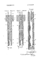
The drawings show in FIG. 1 a probe with the light source in the handle part and the cell near the liquid-containing cavity;
FIG. 2 the locations are similar but there is a different arrangement of the various items;
FIG. 3 one end of a probe showing a channel into which the fluid to be tested flows.
In the drawing in FIG. 1 the light source is a lamp 1 embedded in the handle 10 of a probe which is a cylindrical block 11 of polymethylmethacrylate. The light passes along the tube 3 in the cylinder after passing through a filter 2. Thence the light is reflected from a silver-backed prism 6 through the liquid in the slot 12 on to the photo-electric cell 5. Leads 13 and 14 connect the cell 5 and the lamp I respectively to a meter and battery. The meter is of conventional form but is kept as small as possible. This is also a desirable feature of the probe instrument itself and that shown in FIG. 1 is only about mm in length. Although the meter is shown separately in the drawings it could be contained in the handle of the device if preferred.
FIG. 2 shows the device in a form suitable for measuring the turbidity of a liquid. In this case the light is passed down the center of the rod or tube into the liquid whence it is scattered to one or more photo-electric cells in the walls of the slot. In both cases an air vent 4 is provided leading from the inside end of the channel so as to prevent liquid from entering it.
FIG. 3 the same reference numerals are used for like parts. Instead of the slot 12 in FIGS. 1 and 2 however a channel 15 is shown into which fluid passes through the part 16.
The device is small enough to be easily portable by the operator so that it may be carried for instance round a factory site and readings taken in any number of vessels as easily as making a reading of temperature.
Alternatively the device can be secured in a flxed position and continuous or intermittent readings taken and transmitted to a recorder. One particular use of this kind which is envisaged is for measuring the optical density or turbidity of the exhaust gases from industrial engines, automobile engines and the like. In such cases the device would require to be shielded from the effects of the heat generated.
We claim I. An instrument for determining the optical density of a fluid comprising an elongated rod having a first free end, and a second end opposite said free end, said rod having an integral, coaxial tubular portion extending therethrough from adjacent said free end toward said opposite end but terminating at a point spaced from said opposite end, said tubular portion having a wall encircling a cavity for receiving said fluid therein and having an opening at the end thereof adjacent said free end for admitting said fluid into said cavity, a lamp embedded in said rod adjacent said opposite end thereof, light transmitting means extending from said lamp to said cavity for transmitting light from said lamp to said cavity and in a rectilinear path across a portion of said cavity and at least one light responsive cell embedded in said tubular portion adjacent said cavity and in said path for receiving light transmitted across said portion of said cavity and hence, through fluid contained therein and producing as electrical signal indicative of the density of said fluid.
2. An instrument as set forth in claim 1, wherein said opening extends from said free end to said cavity, whereby said cavity is open in a direction longitudinally of said rod.
3. An instrument as set forth in claim 2, wherein said rod further comprises at least, one air vent extending from a surface thereof spaced from said free end to a portion of said cavity spaced from said free end of said rod.
4. An instrument as set forth in claim 3, wherein said cell has a light receiving face and is mounted with such face at a wall of said cavity which extends longitudinally of said rod and with such face facing transversely of the length of said rod.
5. An instrument as set forth in claim 4, wherein said light transmitting means projects light centrally of said cavity and further comprising a second light responsive cell embedded in said tubular portion of said rod and having a light receiving face, said second cell being mounted with said face thereof at a portion of the wall of said cavity which is opposite from the side thereof at which said face of said first-mentioned cell is mounted.
6. An instrument as set forth in claim 4, wherein said 'light transmitting means extends to a point adjacent a sidewall of said cavity extending longitudinally of said rod and which is spaced from said light receiving face and said light transmitting means comprises a light reflector at said point and mounted to reflect light from said means across said cavity and onto said face.
7. An instrument as set forth in claim 1, wherein said tubular portion is closed by an end wall at said free end and said opening extends through said first-mentioned wall in a direction transverse to the length of said rod and to the portion of said cavity adjacent said end wall and said rod has an air vent extending from a surface thereof spaced from said free end and said end wall to a portion of said cavity spaced from said end wall and said opening, wherein said cell is embedded in said end wall and is mounted to receive light transmitted longitudinally of said rod across said cavity and wherein said light transmitting means transmits light longitudinally of said rod across said cavity and from a portion of the latter spaced from said cell to said cell.
Claims (7)
1. An instrument for determining the optical density of a fluid comprising an elongated rod having a first free end, and a second end opposite said free end, said rod having an integral, coaxial tubular portion extending therethrough from adjacent said free end toward said opposite end but terminating at a point spaced from said opposite end, said tubular portion having a wall encircling a cavity for receiving said fluid therein and having an opening at the end thereof adjacent said free end for admitting said fluiD into said cavity, a lamp embedded in said rod adjacent said opposite end thereof, light transmitting means extending from said lamp to said cavity for transmitting light from said lamp to said cavity and in a rectilinear path across a portion of said cavity and at least one light responsive cell embedded in said tubular portion adjacent said cavity and in said path for receiving light transmitted across said portion of said cavity and hence, through fluid contained therein and producing as electrical signal indicative of the density of said fluid.
2. An instrument as set forth in claim 1, wherein said opening extends from said free end to said cavity, whereby said cavity is open in a direction longitudinally of said rod.
3. An instrument as set forth in claim 2, wherein said rod further comprises at least one air vent extending from a surface thereof spaced from said free end to a portion of said cavity spaced from said free end of said rod.
4. An instrument as set forth in claim 3, wherein said cell has a light receiving face and is mounted with such face at a wall of said cavity which extends longitudinally of said rod and with such face facing transversely of the length of said rod.
5. An instrument as set forth in claim 4, wherein said light transmitting means projects light centrally of said cavity and further comprising a second light responsive cell embedded in said tubular portion of said rod and having a light receiving face, said second cell being mounted with said face thereof at a portion of the wall of said cavity which is opposite from the side thereof at which said face of said first-mentioned cell is mounted.
6. An instrument as set forth in claim 4, wherein said light transmitting means extends to a point adjacent a sidewall of said cavity extending longitudinally of said rod and which is spaced from said light receiving face and said light transmitting means comprises a light reflector at said point and mounted to reflect light from said means across said cavity and onto said face.
7. An instrument as set forth in claim 1, wherein said tubular portion is closed by an end wall at said free end and said opening extends through said first-mentioned wall in a direction transverse to the length of said rod and to the portion of said cavity adjacent said end wall and said rod has an air vent extending from a surface thereof spaced from said free end and said end wall to a portion of said cavity spaced from said end wall and said opening, wherein said cell is embedded in said end wall and is mounted to receive light transmitted longitudinally of said rod across said cavity and wherein said light transmitting means transmits light longitudinally of said rod across said cavity and from a portion of the latter spaced from said cell to said cell.
Applications Claiming Priority (1)
| Application Number | Priority Date | Filing Date | Title |
|---|---|---|---|
| GB3100670 | 1970-06-26 |
Publications (1)
| Publication Number | Publication Date |
|---|---|
| US3734629A true US3734629A (en) | 1973-05-22 |
Family
ID=10316509
Family Applications (1)
| Application Number | Title | Priority Date | Filing Date |
|---|---|---|---|
| US00155507A Expired - Lifetime US3734629A (en) | 1970-06-26 | 1971-06-22 | Instrument for determining the optical density of fluids |
Country Status (4)
| Country | Link |
|---|---|
| US (1) | US3734629A (en) |
| DE (1) | DE2131191A1 (en) |
| FR (1) | FR2098028A5 (en) |
| GB (1) | GB1331496A (en) |
Cited By (17)
| Publication number | Priority date | Publication date | Assignee | Title |
|---|---|---|---|---|
| US3836253A (en) * | 1973-02-28 | 1974-09-17 | Ford Motor Co | Internal combustion engine coolant system leak detection method |
| US3899688A (en) * | 1972-11-24 | 1975-08-12 | Jacques A Perieres | Device for checking the content of hydrocarbons in a mixture of water and hydrocarbons |
| US4118634A (en) * | 1977-01-03 | 1978-10-03 | Pitney-Bowes, Inc. | Developer solution level detector |
| US4299495A (en) * | 1979-05-17 | 1981-11-10 | Tokyo Shibaura Denki Kabushiki Kaisha | Density meter |
| US4499852A (en) * | 1980-07-15 | 1985-02-19 | Shipley Company Inc. | Apparatus for regulating plating solution in a plating bath |
| US4561779A (en) * | 1983-01-07 | 1985-12-31 | Rikagaku Kenkyusho | Instrument for measuring concentration of substance in suspension |
| US4601303A (en) * | 1984-12-21 | 1986-07-22 | Mobil Oil Corporation | Electro-optical fuel blending process |
| US4677567A (en) * | 1984-12-21 | 1987-06-30 | Mobil Oil Corporation | Fuel blending process |
| US4725148A (en) * | 1984-06-07 | 1988-02-16 | Komatsugawa Chemical Engineering Co., Ltd. | Turbidimeter employing a semiconductor laser diode and a photodiode |
| US4774417A (en) * | 1986-01-29 | 1988-09-27 | Nederlandse Organisatie Voor Toegepast-Natuurwetenschappelijk Onderzoek Tno | Method and device for determining the quantity of dispersed solid material in a liquid |
| US5572326A (en) * | 1992-11-10 | 1996-11-05 | Lightfoot; John A. | Arrangements for measuring the height of a layer of floating liquid |
| US5712710A (en) * | 1996-10-15 | 1998-01-27 | Cetin Karakus | Spectrophotometric probe for insitu measurement |
| US6680777B1 (en) | 2000-11-13 | 2004-01-20 | Snap-On Technologies, Inc. | Automatic transmission fluid tester |
| US20040201835A1 (en) * | 2001-10-11 | 2004-10-14 | John Coates | Low-cost on-line and in-line spectral sensors based on solid-state source and detectors combinations for monitoring lubricants and functional fluids |
| US20070084990A1 (en) * | 2003-08-14 | 2007-04-19 | Microspectral Sensing, Llc | Integrated sensing system approach for handheld spectral measurements |
| US9091151B2 (en) | 2009-11-19 | 2015-07-28 | Halliburton Energy Services, Inc. | Downhole optical radiometry tool |
| US20230034379A1 (en) * | 2019-09-23 | 2023-02-02 | Nirrin Technologies, Inc. | In-Situ Probe |
Families Citing this family (2)
| Publication number | Priority date | Publication date | Assignee | Title |
|---|---|---|---|---|
| US5335067A (en) * | 1992-09-29 | 1994-08-02 | The United States Of America As Represented By The United States Department Of Energy | Spectrophotometric probe |
| RU2638578C1 (en) * | 2016-07-11 | 2017-12-14 | Федеральное Государственное Бюджетное Образовательное Учреждение Высшего Образования "Новосибирский Государственный Технический Университет" | Differential measurer of fluid optical density |
Citations (7)
| Publication number | Priority date | Publication date | Assignee | Title |
|---|---|---|---|---|
| US2203720A (en) * | 1934-12-10 | 1940-06-11 | Dale Service Corp | Apparatus for detecting water intrusion in boreholes |
| US2324304A (en) * | 1939-08-24 | 1943-07-13 | Katzman Jacob | Turbidity meter |
| US2682800A (en) * | 1951-08-25 | 1954-07-06 | Robert V Funk | Photoelectric water locating instrument |
| US3263553A (en) * | 1961-12-12 | 1966-08-02 | Warner Lambert Pharmaceutical | Photoelectric immersion probe |
| US3383979A (en) * | 1964-03-24 | 1968-05-21 | Mark Associates Inc | Colorimeter probe |
| US3551670A (en) * | 1968-07-03 | 1970-12-29 | Bowser Inc | Sludge level detector using an infrared source and detector |
| US3586862A (en) * | 1969-09-15 | 1971-06-22 | Keene Corp | Apparatus for continuous detection and measurement of suspended solids in liquids |
-
1970
- 1970-06-26 GB GB3100670A patent/GB1331496A/en not_active Expired
-
1971
- 1971-06-22 US US00155507A patent/US3734629A/en not_active Expired - Lifetime
- 1971-06-23 DE DE19712131191 patent/DE2131191A1/en active Pending
- 1971-06-25 FR FR7123199A patent/FR2098028A5/fr not_active Expired
Patent Citations (7)
| Publication number | Priority date | Publication date | Assignee | Title |
|---|---|---|---|---|
| US2203720A (en) * | 1934-12-10 | 1940-06-11 | Dale Service Corp | Apparatus for detecting water intrusion in boreholes |
| US2324304A (en) * | 1939-08-24 | 1943-07-13 | Katzman Jacob | Turbidity meter |
| US2682800A (en) * | 1951-08-25 | 1954-07-06 | Robert V Funk | Photoelectric water locating instrument |
| US3263553A (en) * | 1961-12-12 | 1966-08-02 | Warner Lambert Pharmaceutical | Photoelectric immersion probe |
| US3383979A (en) * | 1964-03-24 | 1968-05-21 | Mark Associates Inc | Colorimeter probe |
| US3551670A (en) * | 1968-07-03 | 1970-12-29 | Bowser Inc | Sludge level detector using an infrared source and detector |
| US3586862A (en) * | 1969-09-15 | 1971-06-22 | Keene Corp | Apparatus for continuous detection and measurement of suspended solids in liquids |
Cited By (21)
| Publication number | Priority date | Publication date | Assignee | Title |
|---|---|---|---|---|
| US3899688A (en) * | 1972-11-24 | 1975-08-12 | Jacques A Perieres | Device for checking the content of hydrocarbons in a mixture of water and hydrocarbons |
| US3836253A (en) * | 1973-02-28 | 1974-09-17 | Ford Motor Co | Internal combustion engine coolant system leak detection method |
| US4118634A (en) * | 1977-01-03 | 1978-10-03 | Pitney-Bowes, Inc. | Developer solution level detector |
| US4299495A (en) * | 1979-05-17 | 1981-11-10 | Tokyo Shibaura Denki Kabushiki Kaisha | Density meter |
| US4499852A (en) * | 1980-07-15 | 1985-02-19 | Shipley Company Inc. | Apparatus for regulating plating solution in a plating bath |
| US4561779A (en) * | 1983-01-07 | 1985-12-31 | Rikagaku Kenkyusho | Instrument for measuring concentration of substance in suspension |
| US4725148A (en) * | 1984-06-07 | 1988-02-16 | Komatsugawa Chemical Engineering Co., Ltd. | Turbidimeter employing a semiconductor laser diode and a photodiode |
| US4601303A (en) * | 1984-12-21 | 1986-07-22 | Mobil Oil Corporation | Electro-optical fuel blending process |
| US4677567A (en) * | 1984-12-21 | 1987-06-30 | Mobil Oil Corporation | Fuel blending process |
| US4774417A (en) * | 1986-01-29 | 1988-09-27 | Nederlandse Organisatie Voor Toegepast-Natuurwetenschappelijk Onderzoek Tno | Method and device for determining the quantity of dispersed solid material in a liquid |
| US5572326A (en) * | 1992-11-10 | 1996-11-05 | Lightfoot; John A. | Arrangements for measuring the height of a layer of floating liquid |
| US5712710A (en) * | 1996-10-15 | 1998-01-27 | Cetin Karakus | Spectrophotometric probe for insitu measurement |
| US6680777B1 (en) | 2000-11-13 | 2004-01-20 | Snap-On Technologies, Inc. | Automatic transmission fluid tester |
| US20040201835A1 (en) * | 2001-10-11 | 2004-10-14 | John Coates | Low-cost on-line and in-line spectral sensors based on solid-state source and detectors combinations for monitoring lubricants and functional fluids |
| US7339657B2 (en) | 2001-10-11 | 2008-03-04 | Sentelligence, Inc. | Low-cost on-line and in-line spectral sensors based on solid-state source and detectors combinations for monitoring lubricants and functional fluids |
| US20070084990A1 (en) * | 2003-08-14 | 2007-04-19 | Microspectral Sensing, Llc | Integrated sensing system approach for handheld spectral measurements |
| US20080265146A1 (en) * | 2003-08-14 | 2008-10-30 | Microptix Technologies, Llc | Integrated sensing module for handheld spectral measurements |
| US7459713B2 (en) | 2003-08-14 | 2008-12-02 | Microptix Technologies, Llc | Integrated sensing system approach for handheld spectral measurements having a disposable sample handling apparatus |
| US7907282B2 (en) | 2003-08-14 | 2011-03-15 | Microptix Technologies, Llc | Integrated sensing module for handheld spectral measurements |
| US9091151B2 (en) | 2009-11-19 | 2015-07-28 | Halliburton Energy Services, Inc. | Downhole optical radiometry tool |
| US20230034379A1 (en) * | 2019-09-23 | 2023-02-02 | Nirrin Technologies, Inc. | In-Situ Probe |
Also Published As
| Publication number | Publication date |
|---|---|
| FR2098028A5 (en) | 1972-03-03 |
| GB1331496A (en) | 1973-09-26 |
| DE2131191A1 (en) | 1971-12-30 |
Similar Documents
| Publication | Publication Date | Title |
|---|---|---|
| US3734629A (en) | Instrument for determining the optical density of fluids | |
| US3573470A (en) | Plural output optimetric sample cell and analysis system | |
| CA1172058A (en) | Analytical optical instruments | |
| US3319514A (en) | Submersible turbidity detector unit | |
| US3740155A (en) | Colorimeter probe | |
| US3263553A (en) | Photoelectric immersion probe | |
| KR102276319B1 (en) | Sample-receiving elements, assay sets, and methods for analyzing liquids, particularly cooling lubricant emulsions | |
| US4037973A (en) | Light sensitive device for measuring particles in a liquid | |
| US2427013A (en) | Densitometer for measuring the light transmission of a fluid while submerged therein | |
| US4441358A (en) | Automated ultrasonic solution viscometer | |
| US10145789B2 (en) | Immersion refractometer | |
| US3200700A (en) | Photoelectric comparison apparatus for indicating the amount of contamination in liquids | |
| US3733130A (en) | Slotted probe for spectroscopic measurements | |
| US3918817A (en) | Turbidimeters | |
| CA1058414A (en) | Optical analytical device, waveguide and method | |
| US6118134A (en) | Optical mass gauge sensor having an energy per unit area of illumination detection | |
| US3177760A (en) | Apparatus embodying plural light paths for measuring the turbidity of a fluid | |
| US3506359A (en) | Apparatus for measuring light absorption of a sample | |
| US1938544A (en) | Colorimeter | |
| Newell | In situ refractometry for concentration measurements in refrigeration systems | |
| JPS56132566A (en) | Thermostat photometrical apparatus | |
| US20200408680A1 (en) | Optical immersion refractometer probe | |
| JPH02259451A (en) | Turbidity meter | |
| GB2092742A (en) | Bubble flowmeter | |
| GB2134254A (en) | Refractometer for fluids |