US3717532A - Method and apparatus for producing controllably oriented fibrous product - Google Patents
Method and apparatus for producing controllably oriented fibrous product Download PDFInfo
- Publication number
- US3717532A US3717532A US00101370A US3717532DA US3717532A US 3717532 A US3717532 A US 3717532A US 00101370 A US00101370 A US 00101370A US 3717532D A US3717532D A US 3717532DA US 3717532 A US3717532 A US 3717532A
- Authority
- US
- United States
- Prior art keywords
- web
- cog
- traveling
- fibers
- fiber
- Prior art date
- Legal status (The legal status is an assumption and is not a legal conclusion. Google has not performed a legal analysis and makes no representation as to the accuracy of the status listed.)
- Expired - Lifetime
Links
- 238000000034 method Methods 0.000 title claims abstract description 35
- 239000000835 fiber Substances 0.000 claims abstract description 107
- 230000001360 synchronised effect Effects 0.000 claims abstract description 10
- 229920001971 elastomer Polymers 0.000 claims description 5
- 239000000806 elastomer Substances 0.000 claims description 4
- 229920002635 polyurethane Polymers 0.000 claims description 4
- 239000004814 polyurethane Substances 0.000 claims description 4
- 238000004519 manufacturing process Methods 0.000 abstract description 9
- 239000011230 binding agent Substances 0.000 description 15
- 239000000463 material Substances 0.000 description 11
- 229920000297 Rayon Polymers 0.000 description 7
- 229920000126 latex Polymers 0.000 description 5
- 230000000704 physical effect Effects 0.000 description 5
- 239000004816 latex Substances 0.000 description 4
- 229920000915 polyvinyl chloride Polymers 0.000 description 4
- 239000004800 polyvinyl chloride Substances 0.000 description 4
- 239000002964 rayon Substances 0.000 description 4
- 239000004677 Nylon Substances 0.000 description 3
- 230000008901 benefit Effects 0.000 description 3
- 239000007767 bonding agent Substances 0.000 description 3
- 230000009977 dual effect Effects 0.000 description 3
- 230000000694 effects Effects 0.000 description 3
- 229920001778 nylon Polymers 0.000 description 3
- 241000237858 Gastropoda Species 0.000 description 2
- 230000009471 action Effects 0.000 description 2
- 239000000853 adhesive Substances 0.000 description 2
- 230000001070 adhesive effect Effects 0.000 description 2
- 230000006835 compression Effects 0.000 description 2
- 238000007906 compression Methods 0.000 description 2
- 230000035515 penetration Effects 0.000 description 2
- 239000007787 solid Substances 0.000 description 2
- 239000007921 spray Substances 0.000 description 2
- QTBSBXVTEAMEQO-UHFFFAOYSA-M Acetate Chemical compound CC([O-])=O QTBSBXVTEAMEQO-UHFFFAOYSA-M 0.000 description 1
- 244000198134 Agave sisalana Species 0.000 description 1
- 244000025254 Cannabis sativa Species 0.000 description 1
- 235000012766 Cannabis sativa ssp. sativa var. sativa Nutrition 0.000 description 1
- 235000012765 Cannabis sativa ssp. sativa var. spontanea Nutrition 0.000 description 1
- 229920000742 Cotton Polymers 0.000 description 1
- 229920006385 Geon Polymers 0.000 description 1
- 244000299507 Gossypium hirsutum Species 0.000 description 1
- 239000004743 Polypropylene Substances 0.000 description 1
- 229910000831 Steel Inorganic materials 0.000 description 1
- 241000282887 Suidae Species 0.000 description 1
- NIXOWILDQLNWCW-UHFFFAOYSA-N acrylic acid group Chemical group C(C=C)(=O)O NIXOWILDQLNWCW-UHFFFAOYSA-N 0.000 description 1
- 229910052782 aluminium Inorganic materials 0.000 description 1
- XAGFODPZIPBFFR-UHFFFAOYSA-N aluminium Chemical compound [Al] XAGFODPZIPBFFR-UHFFFAOYSA-N 0.000 description 1
- NTXGQCSETZTARF-UHFFFAOYSA-N buta-1,3-diene;prop-2-enenitrile Chemical compound C=CC=C.C=CC#N NTXGQCSETZTARF-UHFFFAOYSA-N 0.000 description 1
- 235000009120 camo Nutrition 0.000 description 1
- 230000008859 change Effects 0.000 description 1
- 235000005607 chanvre indien Nutrition 0.000 description 1
- 239000011248 coating agent Substances 0.000 description 1
- 238000000576 coating method Methods 0.000 description 1
- 238000006073 displacement reaction Methods 0.000 description 1
- 239000013536 elastomeric material Substances 0.000 description 1
- 238000004049 embossing Methods 0.000 description 1
- 239000004744 fabric Substances 0.000 description 1
- 239000003365 glass fiber Substances 0.000 description 1
- 238000010438 heat treatment Methods 0.000 description 1
- 239000011487 hemp Substances 0.000 description 1
- 229940090441 infed Drugs 0.000 description 1
- 239000012784 inorganic fiber Substances 0.000 description 1
- 230000003993 interaction Effects 0.000 description 1
- 239000007788 liquid Substances 0.000 description 1
- 229910052751 metal Inorganic materials 0.000 description 1
- 239000002184 metal Substances 0.000 description 1
- 150000002739 metals Chemical class 0.000 description 1
- 238000012986 modification Methods 0.000 description 1
- 230000004048 modification Effects 0.000 description 1
- 230000000149 penetrating effect Effects 0.000 description 1
- 229920002239 polyacrylonitrile Polymers 0.000 description 1
- 229920000728 polyester Polymers 0.000 description 1
- -1 polypropylene Polymers 0.000 description 1
- 229920001155 polypropylene Polymers 0.000 description 1
- 229920000131 polyvinylidene Polymers 0.000 description 1
- 230000008569 process Effects 0.000 description 1
- 238000004080 punching Methods 0.000 description 1
- 229920005989 resin Polymers 0.000 description 1
- 239000011347 resin Substances 0.000 description 1
- 238000007493 shaping process Methods 0.000 description 1
- 239000002904 solvent Substances 0.000 description 1
- 238000005507 spraying Methods 0.000 description 1
- 239000007858 starting material Substances 0.000 description 1
- 239000010959 steel Substances 0.000 description 1
- 229920003051 synthetic elastomer Polymers 0.000 description 1
- 229920002994 synthetic fiber Polymers 0.000 description 1
- 239000012209 synthetic fiber Substances 0.000 description 1
- 229920001169 thermoplastic Polymers 0.000 description 1
- 239000004416 thermosoftening plastic Substances 0.000 description 1
- 230000005945 translocation Effects 0.000 description 1
- XLYOFNOQVPJJNP-UHFFFAOYSA-N water Substances O XLYOFNOQVPJJNP-UHFFFAOYSA-N 0.000 description 1
Images


Classifications
-
- B—PERFORMING OPERATIONS; TRANSPORTING
- B31—MAKING ARTICLES OF PAPER, CARDBOARD OR MATERIAL WORKED IN A MANNER ANALOGOUS TO PAPER; WORKING PAPER, CARDBOARD OR MATERIAL WORKED IN A MANNER ANALOGOUS TO PAPER
- B31F—MECHANICAL WORKING OR DEFORMATION OF PAPER, CARDBOARD OR MATERIAL WORKED IN A MANNER ANALOGOUS TO PAPER
- B31F1/00—Mechanical deformation without removing material, e.g. in combination with laminating
- B31F1/07—Embossing, i.e. producing impressions formed by locally deep-drawing, e.g. using rolls provided with complementary profiles
-
- B—PERFORMING OPERATIONS; TRANSPORTING
- B31—MAKING ARTICLES OF PAPER, CARDBOARD OR MATERIAL WORKED IN A MANNER ANALOGOUS TO PAPER; WORKING PAPER, CARDBOARD OR MATERIAL WORKED IN A MANNER ANALOGOUS TO PAPER
- B31F—MECHANICAL WORKING OR DEFORMATION OF PAPER, CARDBOARD OR MATERIAL WORKED IN A MANNER ANALOGOUS TO PAPER
- B31F2201/00—Mechanical deformation of paper or cardboard without removing material
- B31F2201/07—Embossing
- B31F2201/0707—Embossing by tools working continuously
- B31F2201/0715—The tools being rollers
- B31F2201/0723—Characteristics of the rollers
- B31F2201/0728—Material
-
- B—PERFORMING OPERATIONS; TRANSPORTING
- B31—MAKING ARTICLES OF PAPER, CARDBOARD OR MATERIAL WORKED IN A MANNER ANALOGOUS TO PAPER; WORKING PAPER, CARDBOARD OR MATERIAL WORKED IN A MANNER ANALOGOUS TO PAPER
- B31F—MECHANICAL WORKING OR DEFORMATION OF PAPER, CARDBOARD OR MATERIAL WORKED IN A MANNER ANALOGOUS TO PAPER
- B31F2201/00—Mechanical deformation of paper or cardboard without removing material
- B31F2201/07—Embossing
- B31F2201/0707—Embossing by tools working continuously
- B31F2201/0715—The tools being rollers
- B31F2201/0723—Characteristics of the rollers
- B31F2201/0733—Pattern
-
- B—PERFORMING OPERATIONS; TRANSPORTING
- B31—MAKING ARTICLES OF PAPER, CARDBOARD OR MATERIAL WORKED IN A MANNER ANALOGOUS TO PAPER; WORKING PAPER, CARDBOARD OR MATERIAL WORKED IN A MANNER ANALOGOUS TO PAPER
- B31F—MECHANICAL WORKING OR DEFORMATION OF PAPER, CARDBOARD OR MATERIAL WORKED IN A MANNER ANALOGOUS TO PAPER
- B31F2201/00—Mechanical deformation of paper or cardboard without removing material
- B31F2201/07—Embossing
- B31F2201/0707—Embossing by tools working continuously
- B31F2201/0715—The tools being rollers
- B31F2201/0723—Characteristics of the rollers
- B31F2201/0738—Cross sectional profile of the embossments
-
- B—PERFORMING OPERATIONS; TRANSPORTING
- B31—MAKING ARTICLES OF PAPER, CARDBOARD OR MATERIAL WORKED IN A MANNER ANALOGOUS TO PAPER; WORKING PAPER, CARDBOARD OR MATERIAL WORKED IN A MANNER ANALOGOUS TO PAPER
- B31F—MECHANICAL WORKING OR DEFORMATION OF PAPER, CARDBOARD OR MATERIAL WORKED IN A MANNER ANALOGOUS TO PAPER
- B31F2201/00—Mechanical deformation of paper or cardboard without removing material
- B31F2201/07—Embossing
- B31F2201/0707—Embossing by tools working continuously
- B31F2201/0715—The tools being rollers
- B31F2201/0741—Roller cooperating with a non-even counter roller
- B31F2201/0743—Roller cooperating with a non-even counter roller having a matching profile
-
- B—PERFORMING OPERATIONS; TRANSPORTING
- B31—MAKING ARTICLES OF PAPER, CARDBOARD OR MATERIAL WORKED IN A MANNER ANALOGOUS TO PAPER; WORKING PAPER, CARDBOARD OR MATERIAL WORKED IN A MANNER ANALOGOUS TO PAPER
- B31F—MECHANICAL WORKING OR DEFORMATION OF PAPER, CARDBOARD OR MATERIAL WORKED IN A MANNER ANALOGOUS TO PAPER
- B31F2201/00—Mechanical deformation of paper or cardboard without removing material
- B31F2201/07—Embossing
- B31F2201/0707—Embossing by tools working continuously
- B31F2201/0754—The tools being other than rollers, e.g. belts or plates
-
- B—PERFORMING OPERATIONS; TRANSPORTING
- B31—MAKING ARTICLES OF PAPER, CARDBOARD OR MATERIAL WORKED IN A MANNER ANALOGOUS TO PAPER; WORKING PAPER, CARDBOARD OR MATERIAL WORKED IN A MANNER ANALOGOUS TO PAPER
- B31F—MECHANICAL WORKING OR DEFORMATION OF PAPER, CARDBOARD OR MATERIAL WORKED IN A MANNER ANALOGOUS TO PAPER
- B31F2201/00—Mechanical deformation of paper or cardboard without removing material
- B31F2201/07—Embossing
- B31F2201/0756—Characteristics of the incoming material, e.g. creped, embossed, corrugated
-
- B—PERFORMING OPERATIONS; TRANSPORTING
- B31—MAKING ARTICLES OF PAPER, CARDBOARD OR MATERIAL WORKED IN A MANNER ANALOGOUS TO PAPER; WORKING PAPER, CARDBOARD OR MATERIAL WORKED IN A MANNER ANALOGOUS TO PAPER
- B31F—MECHANICAL WORKING OR DEFORMATION OF PAPER, CARDBOARD OR MATERIAL WORKED IN A MANNER ANALOGOUS TO PAPER
- B31F2201/00—Mechanical deformation of paper or cardboard without removing material
- B31F2201/07—Embossing
- B31F2201/0758—Characteristics of the embossed product
-
- B—PERFORMING OPERATIONS; TRANSPORTING
- B31—MAKING ARTICLES OF PAPER, CARDBOARD OR MATERIAL WORKED IN A MANNER ANALOGOUS TO PAPER; WORKING PAPER, CARDBOARD OR MATERIAL WORKED IN A MANNER ANALOGOUS TO PAPER
- B31F—MECHANICAL WORKING OR DEFORMATION OF PAPER, CARDBOARD OR MATERIAL WORKED IN A MANNER ANALOGOUS TO PAPER
- B31F2201/00—Mechanical deformation of paper or cardboard without removing material
- B31F2201/07—Embossing
- B31F2201/0771—Other aspects of the embossing operations
- B31F2201/0774—Multiple successive embossing operations
-
- B—PERFORMING OPERATIONS; TRANSPORTING
- B31—MAKING ARTICLES OF PAPER, CARDBOARD OR MATERIAL WORKED IN A MANNER ANALOGOUS TO PAPER; WORKING PAPER, CARDBOARD OR MATERIAL WORKED IN A MANNER ANALOGOUS TO PAPER
- B31F—MECHANICAL WORKING OR DEFORMATION OF PAPER, CARDBOARD OR MATERIAL WORKED IN A MANNER ANALOGOUS TO PAPER
- B31F2201/00—Mechanical deformation of paper or cardboard without removing material
- B31F2201/07—Embossing
- B31F2201/0784—Auxiliary operations
-
- Y—GENERAL TAGGING OF NEW TECHNOLOGICAL DEVELOPMENTS; GENERAL TAGGING OF CROSS-SECTIONAL TECHNOLOGIES SPANNING OVER SEVERAL SECTIONS OF THE IPC; TECHNICAL SUBJECTS COVERED BY FORMER USPC CROSS-REFERENCE ART COLLECTIONS [XRACs] AND DIGESTS
- Y10—TECHNICAL SUBJECTS COVERED BY FORMER USPC
- Y10T—TECHNICAL SUBJECTS COVERED BY FORMER US CLASSIFICATION
- Y10T156/00—Adhesive bonding and miscellaneous chemical manufacture
- Y10T156/10—Methods of surface bonding and/or assembly therefor
- Y10T156/1002—Methods of surface bonding and/or assembly therefor with permanent bending or reshaping or surface deformation of self sustaining lamina
- Y10T156/1007—Running or continuous length work
-
- Y—GENERAL TAGGING OF NEW TECHNOLOGICAL DEVELOPMENTS; GENERAL TAGGING OF CROSS-SECTIONAL TECHNOLOGIES SPANNING OVER SEVERAL SECTIONS OF THE IPC; TECHNICAL SUBJECTS COVERED BY FORMER USPC CROSS-REFERENCE ART COLLECTIONS [XRACs] AND DIGESTS
- Y10—TECHNICAL SUBJECTS COVERED BY FORMER USPC
- Y10T—TECHNICAL SUBJECTS COVERED BY FORMER US CLASSIFICATION
- Y10T428/00—Stock material or miscellaneous articles
- Y10T428/24—Structurally defined web or sheet [e.g., overall dimension, etc.]
- Y10T428/24628—Nonplanar uniform thickness material
- Y10T428/24636—Embodying mechanically interengaged strand[s], strand-portion[s] or strand-like strip[s] [e.g., weave, knit, etc.]
-
- Y—GENERAL TAGGING OF NEW TECHNOLOGICAL DEVELOPMENTS; GENERAL TAGGING OF CROSS-SECTIONAL TECHNOLOGIES SPANNING OVER SEVERAL SECTIONS OF THE IPC; TECHNICAL SUBJECTS COVERED BY FORMER USPC CROSS-REFERENCE ART COLLECTIONS [XRACs] AND DIGESTS
- Y10—TECHNICAL SUBJECTS COVERED BY FORMER USPC
- Y10T—TECHNICAL SUBJECTS COVERED BY FORMER US CLASSIFICATION
- Y10T428/00—Stock material or miscellaneous articles
- Y10T428/29—Coated or structually defined flake, particle, cell, strand, strand portion, rod, filament, macroscopic fiber or mass thereof
- Y10T428/2904—Staple length fiber
Definitions
- ABSTRACT The method of making a non-woven fibrous pad comprising a three-dimensional network of individual fibers interconnected by bonding means where they cross and contact each other and having a surface textured with a pattern of undulating elevations separated [63] Continuation-impart of Scr. No. 777,698, Nov. 21, by a respective Pattern of undulating depressions 1968, Pat. No. 3,616,159. wherein each of the elevations comprises a structural dome in which the ratio of cap wall unit weight to [52] U.S. Cl.
- the method [51] Int. Cl. ..B3lf l/00 includes the step of subjecting an unbonded web of [58] Field of Search ..156/ 196, 199, 219-221, mechanically engaged fibers to successive forming 156/228, 252, 253, 290, 323, 459, 513, 582, operations between partly meshing, multiple cogged 585, 586, 590, 592, 595; 264/119; 198/162, work members relocating fibers from the regions 226,170,172;161/109,113,DIG.3,130, forming the peaks of the elevations to the regions 131; 19/161 P, 93, 94, 95, 100, 106, 172, forming the sidewalls thereof.
- Apparatus for producing such a fibrous pad comprises [56] References Cited a pair of fiber orienting arrangements, one of which includes means forming a traveling cog surface and UNITED STATES PATENTS the other of which includes a plurality of synchronized cog members meshing successively with the cog surface.
- One of the fiber orienting arrangements includes 2,464,301 3/1949 Francis Ix/582x a plurality of closely laterally spaced cog elements 2,764,193 9/1956 Knowles....
- This invention relates generally to the art of nonwoven fibrous structures and more particularly to nonwoven resilient padding.
- Another object of the invention is to provide advantageous methods and apparatus for the production of a non-woven, fibrous pad which is characterized by an unusually high resiliency per pound of fiber.
- Still another object of the invention is to provide advantageous methods and apparatus for the production of a non-woven, fibrous pad which has a greater overall volume and a greater surface area than the web from which it is produced.
- Yet another object of the invention is to provide advantageous methods and apparatus for the production of a pad of the type described which is amenable to the addition of high levels of binder.
- a yet further object of the invention is to provide advantageous methods and apparatus for the production of such a pad in which the fibers in the dome sidewalls are selectively oriented to resist compressive loads applied to the face of the pad.
- FIG. 1 is a perspective view of a piece of non-woven, fibrous padding constructed and produced in compliance with the present invention
- FIG. 2 is an enlarged elevational view taken in crosssection along the line 2-2 of FIG. 1 and showing the undulating elevations and depressions as well as the general orientation of the fibers in the pad of FIG. 1;
- FIG. 3 is a schematic elevational view of apparatus arranged to produce the fibrous pad of the invention.
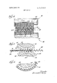
- FIG. 4 is an enlarged front elevational view of the cogged, fiber-orienting rolls or cylinders used in the apparatus of FIG. 3;
- FIG. 5 is an end elevational view in cross-section showing the preforming or bulking rolls used in the apparatus of FIG. 3;
- FIG. 6 is a fragmentary view somewhat similar to the showing of FIG. 5 but illustrating the alternate arrangement of the cog teeth
- FIG. 7 is an elevational view of one type of fiberorienting apparatus useful for producing the fibrous pad of the invention.
- FIG. 8 is a schematic view of a modified form of apparatus for producing the fibrous pad of the invention.
- FIG. 9 is an elevational view of a type of fiber-orienting apparatus similar to that of FIG. 7 but incorporating additional features;
- FIG. 10 is an enlarged front elevational view of cogged, fiber-orienting rolls or cylinders of the type used in the apparatus of FIG. 3, but incorporating additional features;
- FIG. 1 1 is a schematic view of a modified form of the apparatus for producing the fibrous pad of the invention
- FIG. 12 is a chart of one example showing the relation of the resiliency of the pad to fiber orientation and the amount of working to which the pad is subjected in processing.
- FIGS. 13 and 14 are perspective views of the cogged cylinders used in the apparatus of FIG. 3 and arranged with conveyor belt elements to deliver a carded web to the cylinders and to strip a processed web therefrom.
- FIGS. 15 and 16 are perspective views of the apparatus of FIG. 13 further arranged with hold-down belt elements to hold down the web during processing.
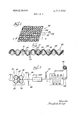
- a non-woven fibrous pad constructed in compliance with the present invention is indicated generally by the reference numeral 20.
- the pad 20 comprises a three-dimensional network of individual fibers 22 that form a surface which is textured with a pattern of undulating elevations 24, elevations 24 being separated by a respective pattern of undulating depressions 26.
- the individual fibers are bonded where they cross and contact each other, as by droplets of a suitable adhesive 28.
- the elevations 24 comprise domeshaped structures whereas the depressions 26 comprise corresponding, inverted dome-shaped structures; and as compared with an ordinary carded web, the pad 20 exhibits an enhanced total surface area and increased resiliency. While the pad 20, like conventional nonwoven materials, has a degree of translucense, it ordinarily has no visible holes penetrating through the product.
- Each of the domes comprising the elevations 24 and the depressions 26 includes a cap wall 30 and a surrounding sidewall 32; and in compliance with the features of the present invention, the fibers making up the domes are distributed in greater concentration in the sidewalls than in the cap walls. More specifically, the fibers in the pad 20 are arranged so that the ratio of cap wall unit weight to the average web unit weight is less than 1.0; and in further accord with the invention, this ratio of cap wall unit weight to the average web unit weight is controlled to be greater than about 0.2, the precise figure for this lower limit being governed by the physical properties which are acceptable in each given situation and selected to be such that no appreciable perforation of the pad is developed.
- the individual fibers in the sidewalls 32 are advantageously oriented generally parallel with the thickness dimension of the pad 20.
- the described arrangement achieves a high degree of resiliency per pound of fiber used and is more readily penetrated by bonding liquids than the starting web. 4
- a wide variety of fibers may be used in the pad 20; and at the present time, out staple fiber having a crimp or fibrils to encourage mechanical interlocking is preferred.
- expanded tow may also be employed.
- the fibers may be natural fibers such as hogs hair, cotton, sisal and hemp, or they may be synthetic fibers such as nylon, rayon acetate, polyester, acrylonitrile polymers, polypropylene, and polyvinylidene chloride-polyvinyl chloride copolymers.
- Inorganic fibers such as glass fibers may also be used, and any of these various fibers may be used alone or in admixture with others.
- binder While substantially any binder which is compatible with the fiber may be employed, exemplary binders include acrylic, polyvinyl chloride and synthetic elastomer latices. Binder may be added in quantities varying from to 100 percent of the weight of fiber utilized, Furthermore, bonding of the fibers may also be achieved by momentarily heating thermoplastic fibers to their softening point.
- the individual elevations 24 and depressions 26 may take various shapes such as ellipsoidal (as shown), round, elliptical, or nearly square for example.
- the vertical projection of an individual elevation or depression is a rectangle measuring approximately. one cm. by one-half cm. Elevations and depressions of other sizes may also be employed.
- the one-hundred-and-eighty degree phase relationship between adjacent rows of elevations and depressions need not be adhered to, and other phase relationships may be used. It is also possible to fill the depressions on one side of the pad as with the same or a dissimilar fiber or with a foamed resin.
- a resilient non-woven product such as the pad 20 is produced by reorienting the fibers of a lofted web in successive stages. Most fibers can be thus reoriented in a substantially dry state. For certain types of fibers, however, it may be desirable prior to the reorientation step to wet the fibers with a fiuid such as water or to bond the web lightly with a binder or by needling or the like. Such pretreatment is useful when the web is otherwise difficult to process because of such factors as short fiber length, heavy denier, high degree of crimp or high degree of natural spring back or liveliness.
- the massaging, rubbing or wiping action of smooth, partially intermeshing cog teeth serves to relocate generally the horizontally disposed fibers from the incipiently forming dome caps of the undulating elevations and depressions to the more vertically disposed sections of the dome sidewalls. Whether the fibers in the initial web are oriented to produce isotropic properties or anisotropic properties is immaterial to the practice of the present invention since a reorientation and redistribution of the fibers is achieved.
- a carded web 34 of cut staple fibers is advanced to a processing station 36 where the web is subjected to successive forming operations between partly meshing, multiple cogged work members, specifically first stage forming rolls 38 and second stage forming rolls 40. Only two forming stages are suggested in FIG. 3 for simplicity of illustration; and it is to be recognized that the optimum number of forming operations will vary with such factors as the type and length of the fibers in the web 34, the thickness and density of the starting web and the depth of the cog teeth on the work members 38 and 40.
- the depth of the cog teeth in the subsequent work members be substantially the same as the depth of the cog teeth in the preceding work members, although under certain circumstances it is desirable that the subsequent work members have a greater cog tooth depth or that the subsequent work members be meshed to a greater degree than the preceding work members.
- engagement of the various work members with the web being processed is synchronized as by means of the mechanical interlock achieved through common drive gearing 42.
- the processing which the web 34 receives at station 36 produces an orientation of the fibers of the type generally illustrated in FIGS. 1 and 2, and this process step bulks the structure and generates a high percentage of load bearing fibers without deliberately breaking them, such as occurs during needling for example.
- An unbonded web 44 formed with patterns of undulating elevations and depressions exits from the station 36; and frictional effects between the fibers, arising due to the high individual fiber crimp or fibril-interlock, are relied upon initially to maintain integrity of the structure. Subsequent bonding achieves permanency of the web. In order to accommodate high machine speeds, it is advantageous to apply the bonding agent in stages in order to avoid distortion of light web structures.
- a light coating on the order of 0.1 0.2 ounces per square yard may be applied to one or both surfaces of the web 44 by spray nozzles 46 or other suitable means.
- the bonding agent applied by means of the nozzles 46 is suitably dissolved or dispersed in a solvent for ease of application and to promote penetration into the web 44.
- the bonding agent is dried or cured in a drier 48; and upon leaving the drier 48, the web can be treated with less care and concern.
- Additional binder material is then supplied by a surface spray station or saturator 50 and the web is heated to cure or dry the binder in a drier 52 where the web is advantageously festooned.
- the finished web 54 emerges from the drier 52 from whence it can be directed for further processing or wound up in a roll 56 for shipment.
- each of these elements is similarly fabricated to comprise a central drum or shaft 58 upon which is mounted a plurality of cog rings 60.
- Each of the cog rings 60 carries a suitable number of cog teeth 62; and to produce spacing of the cog teeth 62 axially of the shaft or drum 58, the cog rings 60 are provided with lateral shoulders 64, best seen in FIG. 4.
- spacing of paired shafts 58 while taking into consideration the length of the cog teeth 62, is selected to provide a relatively deep but only partly meshed engagement of the cog teeth of the upper and lower rolls whereby to accommodate the fibrous web therebetween without excessive compression.
- the lateral faces of the cog teeth 62 are tapered in order to' cooperate with the axial spacing afforded by shoulders 64 in accommodating the material of the fibrous web.
- the shape of the individual cog teeth in transverse cross-section is selected to correspond with the vertical projection of the elevations and undulations to be formed in the fibrous web, and the preliminary work members 38 may be considered as bulking rolls in that the pattern of undulations is well established even in a single pass, as is shown in FIG. 5.
- the subsequent work members may be correspondingly considered as fiber-orienting rolls which redistribute the individual fibers into the desired configuration described hereinabove.
- the cog rings 60 of each work drum are mounted with a relative angular displacement as described hereinabove and as shown in FIG. 6.
- precise intermeshing registration is maintained between each cogged work member and its intermeshing element.
- the cog teeth 62 are alternated with the corresponding cog spaces across the face of the roll or drum.
- the cog teeth may be staggered by a fractional pitch other than onehalf pitch in either direction.
- the cog teeth are fabricated to be smooth surfaced and with rounded corners and edges in order to prevent catching individual fibers from the processed web.
- the cog teeth and even the cog rings themselves are preferably fabricated from an elastomeric material such as an unfoamed polyurethane material of about 90 durometer hardness on the Shore A scale. So fabricated, intrusion of a hard foreign object between the relatively deeply engaged cog teeth is prevented from facturing the teeth or overloading the bearings for the work cylinders.
- Some polyurethanes of a moldable nature are also of advantage for manufacture of the cog teeth and cog rings since they possess a low coefficient of friction and exhibit good wear resistance. Cogs of harder materials, including metals such as steel, aluminum, etc. would also give good results.
- a processing machine is particularly arranged to accommodate a selected number of plural forming operations from two to seven. More specifically, a primary rotatable work member 68 is mounted on a horizontal shaft 70 and includes a tubular hub 72 which rotatably receives the shaft 70, an outer cylindrical drum 74, and radial spokes or arms 76 which attach cylinder 74 to the hub 72.
- the outer surface of cylinder 74 is provided with a pattern of cog teeth 78 similar to the cog teeth described with reference to FIGS. 4-6 hereinabove; and advantageously, the drum 74 is arranged to have a relatively large diameter in order that the height of the cog teeth will be small compared with the circumference of the drum for ease in stripping the processed web.
- Arcuately spaced about the periphery of cylinder 78 are seven, smaller diameter satellite rolls or drums 80.
- Each of the satellite drums 80 is suitably rotatably mounted on a radially adjustably positionable bracket 82 which is secured to a machine frame, a portion of which is indicated at 82, by means of adjustment screws 84.
- the satellite drums 80 are individually provided with multiple cog toothed outer surfaces which are suitably arranged to mesh with the cogged surface of the primary cylinder 74.
- a sprocket wheel 86 is secured to the work member 68 for roation therewith; and correspondingly, an individual sprocket wheel 88 is secured to each of the satellite drums 80 for rotation therewith.
- a sprocket chain 90 is trained over the sprocket wheel 86 and over the individual satellite drum sprocket wheels 88; and in order to insure proper operation of the drive train, a suitable number of idler sprockets 92 are radially adjustably mounted on the machine frame 83 by means of brackets 94 and adjustment screws 96.
- one or more of the idler sprockets 92 will be appropriately repositioned to take up or provide, as the case may be, slack in the sprocket chain 90.
- Rotary driving force may be applied at the central shaft 70 or at one of a pair of outlying sprocket wheels 98.
- the use of the sprockets 88 and chain 90 is preferred for heavy and hard to work fibrous webs. For much usage, however, particularly with light webs, the normal cog engagement serves as an adequate drive means for the satellite rollers.
- an endless infeed and stripper belt arrangement is directed over a system of fixed rollers 102 and positionally adjustable roller 104.
- the rollers 104 are rotatably mounted on brackets 106 which are, in turn, swingably mounted to the machine frame 83 by pivots 108, the brackets 106 being arcuately slotted to pass the shanks of adjustment screws 110.
- the rollers 104 may be moved in respective arcuate paths and positioned to apply a selected degree of tension in the stripper belt arrangement 100.
- the infeed and stripper belt arrangement 100 is trained through the enmeshed, cog toothed work members in a manner to be described more fully hereinafter with respect to FIGS.
- an endless helper belt 112 is driven by a suitably powered drive roll 114 and guided by an idler roll 116 to aid in delivering the carded web 34 to the cogged work members.
- the processed web 44 is passed from the machine 66 and guided by an idler roller 118 to further processing statrons.
- the stripper belt arrangement 100 described above illustrates a particular stripping means which is preferred for use in the invention.
- Any suitable stripping means couldbe used, however, such as flow of air directed between the processed web and the first fiber orienting means.
- the air stream is directed at a point on the first fiber orienting means just beyond the locus of the engagement of the web by the second fiber orienting means.
- a so called air knife is useful to provide and direct this air stream.
- stripping means particularly the stripper belt arrangement 100
- stripping means is not essential for all situations.
- Particularly stable webs of this type may be achieved by prebonding of the web by any suitable means prior to its introduction into the machine.
- suitable means include the use of latent binders, needling, or the like.
- FIG. 8 where two machines similar to the machine 66 described with reference to FIG. 7 are arranged in tandem, one of the machines being inverted in order that the respective work members or satellite drums may engage that side of the web which is opposite to that engaged by the satellite drums of the other machine. Since the tandemized processing machines of FIG. 8, designated respectively by the reference numerals 66a and 66b, are constructed similarly to the processing machine 66 of FIG. 7, like numerals have been used to designate like parts with the suffix letters a and b being employed to distinguish the respective machine elements found in the apparatus of FIG. 8.
- the processing machine 66 is fashioned to support an incoming web of fibers on the cogged surface of primary drum 74 while the cogged surfaces of one or more satellite drums are rotated in synchronism with the primary drum in partly meshed engagement therewith so that the cog teeth of the satellite drum or drums wipe into the web to form respective drum in partly meshed engagement therewith so that the cog teeth of the subsequent drum or drums engage the previously formed depressions and elevations to relocate fibers from the respective crest and root regions thereof to the sidewall regions.
- the fibers are bonded together as previously described so as to produce a resilient fibrous pad of the character of pad 20 described hereinabove.
- FIG. 9 there is shown a fiber orienting machine identical to that of FIG. 7 except that it has a second endless belt arrangement 130 directed over a system which inciudes an adjustable clearance idler roller 132 and return idler rollers 134.
- the operation of the holddown belt arrangement is described more fully hereinafter with respect to FIGS. 15 and 16.
- the roller 132 in FIG. 9 is rotatably mounted on bracket 136 which is, in turn, swingably mounted to support 138 by pivot 140, the bracket 136 being arcuately slotted to pass the shank of adjustment screws 142. This permits positioning of the clearance idler roller 132 to achieve the desired angle at which the belt system 130 breaks away from the web 44 produced by the machine.
- FIG. 11 illustrates a dual machine similar to that described in FIG. 7 but incorporating a second endless belt arrangement 130a and 130b. Included are two machines of the type shown in FIG. 9 and arranged in tandem to cooperate with one another. Parts similar to those in FIG. 9 have been given the same numbers with the suffix letters a and b. It must be recognized, however, that in this dual arrangement the same belt which is the first belt arrangement 10Gb on cylinder 74b is also the second belt arrangement 130a on cylinder 74a.
- one or more of the cooperatively cogged satellite drums are rotated in correspondence with the primary 74a utilizes the same belt which is the second belt arrangement 13017 on cylinder 74b.
- the two primary cylinders of the dual machine must be fully synchronized not only in speed but also in the relative positions of their respectivecogs. This synchronization can be achieved by any suitable means such as the spur gear train 146 shown in FIG. 11.
- the incoming web 34 moves through the machine in the direction shown and is removed as oriented unbonded web 44 for spraying or other processing to fix to web. Operation of the cogged teeth is as described for FIGS. 7 and 8.
- FIG. 12 The effect of utilizing a multiplicity of forming operations in accordance with the principles of the present invention is clear from the data graphically presented in FIG. 12. These data represent work conducted on eight denier rayon viscose and constitute a first working example of the invention. Actual values are set forth as plotted points and generalized relationships are suggested in the form of curves.
- a carded web having an average fiber weight of 2.2 ounces per square yard was employed as the starting material, and uniform amounts of binder were added to the respective samples after processing.
- the binder itself was made up of equal parts of polyvinyl chloride latex and acrilonitrilebutadiene latex.
- slugs having a diameter of about 0.6 cms. were punched out of the cap area of the undulating elevations of each specimen. The elevations themselves had a vertical projected area that measured approximately 1 cm. by 0.5 cm.; and ten slugs were extracted from each sample and their weight averaged for the determination.
- FIGS. 13 and 14 various elements of the work station 36, described with reference to FIGS. 3-6, are shown arranged with an infeed and stripper belt arrangement 120 of the general type suggested for use with the processing machines of FIGS. 7 and 8. It has been found that the formed web has some tendency to cling to one of the cogged members, and it is ordinarily desirable to peel the formed web gently and progressively and without distortion from that member, stripper belts being one advantageous means for accomplishing this objective.
- Use of stripper belt arrangements is of particular advantage with lightweight webs on the order of 1.0 ounces per square yard or less in weight.
- the stripper belt arrangement 120 specifically comprises a plurality of laterally spaced-apart belts 122 which run between the individual cog rings 60 at the root of the space between the cog teeth of the lower work element or drum. As is shown in FIG. 4, the cog rings 60 are fashioned with inwardly sloping surfaces at the shoulders 64 to define grooves 124, the location of individual stripper belts 122 in these grooves 124 being suggested in FIG. 4.
- the individual stripper belts 122 may comprise such things as monofilament nylon, nylon rope, solid rubber strands of circular cross-section, and coiled wire or garter spring belting. The latter material is of particular advantage because of its ease of splicing.
- FIGS. and 16 is shown a second belt arrangement 150 of the type suggested for use with the processing machines of FIGS. 9 and 11. It has been found that with multiple satellite drums 80 cooperating with the primary cylinder 68 of FIG. 9, the webs of some fibers have a tendency, in varying degrees, to be lifted from the primary cylinder surface by a satellite drum and then redeposited on the primary cylinder cog surface by the next successive satellite drum. Such action produces undesirable surface irregularities and, in extreme cases, a non-uniform processed web wherein some areas are thicker than others.
- the second belt arrangement 150 prevents'this undesired effect by holding the web down and maintaining it in contact with the cogged surface 78 of the primary cylinder 68 during all interaction of the primary cylinder 68 with the satellite drurns 80.
- the hold-down belts 144 of the belt arrangement 150 hold down the web 34 as it is fed between the rolls 38 and on into rolls 40 and as the processed web 44 emerges from the rolls 40 it is held down by the belts 144 so that it cannot lift off the belts 122 of the stripper belt arrangement 120.
- the position of the belts 122 and 144 relative to the rolls 40 can be seen in FIG. 10.
- a number of resilient pads were made in compliance with the principles of the invention using two separate cut staple fiber base carded webs, specifically a rayon viscose of 15 denier and a staple length of 1 and 9/16 inches and a rayon viscose of eight denier and one inch cut staple length.
- a single binder was employed at different levels of addition, the binder in each case being equal parts of Geon 580 (polyvinyl chloride latex) and I-Iycar 1552 (acrylonitrile-butadiene latex).
- the fibrous resilient pads of the present invention may be laminated with various fabrics, with paper or with other materials, to be employed in numerous ways that will be readily apparent to the skilled artisan, such as for example in lightweight resilient or insulating structures and padded garments.
- Apparatus for producing a non-woven fibrous pad comprising: first fiber orienting means including means forming a continuous traveling cog surface; and second fiber orienting means including a plurality of individual transversely extending synchronized cog-surfaced members spaced in the direction of travel and meshing successively with said traveling cog surface.
- Apparatus for producing a non-woven fibrous pad comprising: first fiber orienting means including means forming a continuous traveling cog surface; second fiber orienting means including a plurality of individual transversely extending synchronized cog-surfaced members spaced in the direction of travel and meshing successively with said traveling cog surface; and stripping means for stripping a processed web from said first fiber orienting means after the final engagement of said web by said second fiber orienting means.
- Apparatus for producing a non-woven fibrous pad comprising: first fiber orienting means including means forming a continuous traveling cog surface; second fiber orienting means including a plurality of individual transversely extending synchronized cog-surfaced members spaced in the direction of travel and meshing successively with said traveling cog surface, one of said first and second fiber orienting means including a plurality of closely laterally spaced cog elements having channel means therebetween running generally in the direction of travel of said traveling cog surface; and conveyor belt means disposed partly in said channel means and diverging from a meshed region of said first and second fiber orienting means for feeding a fibrous web into said fiber orienting means or stripping a processed web therefrom.
- said conveyor belt means includes laterally spaced belt elements running generally parallel with the direction of travel of said traveling cog surface.
- said conveyor belt means includes first belt elements running generally parallel with the direction of travel of said traveling cog surface directly beneath the fibrous web being processed through said apparatus and second belt elements running parallel to said first belt elements in the same direction directly above and in contact with said fibrous web.
- said conveyor belt means includes first and second belt elements running generally parallel with the direction of travel of said traveling cog surface and third belt elements running transversely of said first belt elements and connected thereto forming a mesh.
- the method of producing a non-woven fibrous pad possessed of a surface textured with a pattern of undulating elevations separated by a respective pattern of undulating depressions from an unbonded web of mechanically engaged fibers comprises: feeding said web to a processing station; subjecting said web to successive forming operations between partly meshing, multiple cogged work members relocating fibers from the regions forming the peaks of said elevations to the regions forming the sidewalls thereof; and bonding said formed web to lock said fibers in their reoriented relationship.
- first forming operations work principally on one side of the web and second forming operations work principally on the opposite side of the web.
- the method of producing a non-woven fibrous pad possessed of a surface textured with a pattern of undulating elevations separated by a respective pattern of undulating depressions from an unbonded web of mechanically engaged fibers comprises: supporting said web on a cogged surface; rotating a first correspondingly cogged drum means in partly meshed engagement with said surface, the cog teeth of said drum means wiping into said web to form said depressions and elevations; rotating a second correspondingly cogged drum means in partly meshed engagement with said surface and subsequent to said first drum means, the cog teeth of said second drum means engaging said depressions and elevations to relocate fibers from the respective crest and root regions thereof to the sidewall regions; and bonding said formed web to lock said fibers in their reoriented relationship.
- said second drum means comprises a plurality of cogged drum elements.
- the method of producing a non-woven fibrous pad possessed of a surface textured with a pattern of undulating elevations separated by a respective pattern of undulating depressions from an unbonded web of mechanically engaged fibers comprises: feeding said web to a processing station; subjecting said web to successive forming operations between partly meshing, multiple cogged work members relocating fibers from the regions forming the peaks of said elevations to the regions forming the sidewalls thereof; progressively peeling the formed web in substantially undistorted condition from a said work member; and bonding said forrried web to lock said fibers in their reoriented relationship.
Landscapes
- Engineering & Computer Science (AREA)
- Mechanical Engineering (AREA)
- Nonwoven Fabrics (AREA)
Abstract
The method of making a non-woven fibrous pad comprising a threedimensional network of individual fibers interconnected by bonding means where they cross and contact each other and having a surface textured with a pattern of undulating elevations separated by a respective pattern of undulating depressions wherein each of the elevations comprises a structural dome in which the ratio of cap wall unit weight to average web unit weight is less than 1.0. The method includes the step of subjecting an unbonded web of mechanically engaged fibers to successive forming operations between partly meshing, multiple cogged work members relocating fibers from the regions forming the peaks of the elevations to the regions forming the sidewalls thereof. Apparatus for producing such a fibrous pad comprises a pair of fiber orienting arrangements, one of which includes means forming a traveling cog surface and the other of which includes a plurality of synchronized cog members meshing successively with the cog surface. One of the fiber orienting arrangements includes a plurality of closely laterally spaced cog elements having channels therebetween aligned generally with the direction of travel of the cog surface, and a conveyor belt arrangement is disposed partly in the channels and diverges from a meshed region of the fiber orienting arrangements for feeding a fibrous web into the orienting arrangements or stripping a processed web therefrom.
Description
United States Patent 11 1 Kamp |4 1 Feb. 20, 1973 1541 METHOD AND APPARATUS FOR PRODUCING CONTROLLABLY ORIENTED FIBROUS PRODUCT [211 App]. No.: 101,370
Related U.S. Application Data Primary Examiner-William A. Powell Attorney-Paul A. Rose, John F. Hohmann and J. Hart Evans [57] ABSTRACT The method of making a non-woven fibrous pad comprising a three-dimensional network of individual fibers interconnected by bonding means where they cross and contact each other and having a surface textured with a pattern of undulating elevations separated [63] Continuation-impart of Scr. No. 777,698, Nov. 21, by a respective Pattern of undulating depressions 1968, Pat. No. 3,616,159. wherein each of the elevations comprises a structural dome in which the ratio of cap wall unit weight to [52] U.S. Cl. ..156/199, 156/459, 161/130 v g web u i weight i less than 1.0. The method [51] Int. Cl. ..B3lf l/00 includes the step of subjecting an unbonded web of [58] Field of Search ..156/ 196, 199, 219-221, mechanically engaged fibers to successive forming 156/228, 252, 253, 290, 323, 459, 513, 582, operations between partly meshing, multiple cogged 585, 586, 590, 592, 595; 264/119; 198/162, work members relocating fibers from the regions 226,170,172;161/109,113,DIG.3,130, forming the peaks of the elevations to the regions 131; 19/161 P, 93, 94, 95, 100, 106, 172, forming the sidewalls thereof.
128; 226/170 172; 26/69 Apparatus for producing such a fibrous pad comprises [56] References Cited a pair of fiber orienting arrangements, one of which includes means forming a traveling cog surface and UNITED STATES PATENTS the other of which includes a plurality of synchronized cog members meshing successively with the cog surface. One of the fiber orienting arrangements includes 2,464,301 3/1949 Francis Ix/582x a plurality of closely laterally spaced cog elements 2,764,193 9/1956 Knowles.... .....l56/459 x having channels therebetween aligned generally with 2,856,323 10/1958 Gord n ,,15 220 X the direction of travel of the cog surface, and a con- 3,025,585 3/1962 Griswold ....19/ 161 P X veyor belt arrangement is disposed partly in the chan- 3,031,500 3/1963 Griswold at .-l6l/70X nels and diverges from a meshed region of the fiber $137,893 7/1964 Gelpke P X orienting arrangements for feeding a fibrous web into 3,369,955 2/1968 Rudloff ..156/595 X the orienting arrangements or stripping a processed FOREIGN PATENTS OR APPLICATIONS web 962.162 7/ 1964 Great'BTFi'n'...iTQQlLIl'LTiI..1'9/1'06 13 cl i 1 Drawing Figures 627 4 JR/ERGZ) fl/F/EA (45) MV\4\\'\I\\A PATENTED Hm I915 3,717. 53 2 SHEET 10F 8 j/r/gle (45) PATENTEDFEBZOIQYK 3,717. 532
SHEET u 0F 8 5g INVENTOR I [d A. K m m PATENTEB FEB 2 0 i975 SHEET 5 OF 8 INVENTOR wai 14.11 01 7% PATENTEUFEBZOIGIB SHEET 6 U? 8 3456789|0H|B lllllllll NUMBER OF FORMING 0PEK4770/V6 QRXK PATENTED FEB 2 01573 SHEET 8 OF 8 METHOD AND APPARATUS FOR PRODUCING CONTROLLABLY ORIENTED FIBROUS PRODUCT RELATED APPLICATIONS This application is a continuation-in-part of my copending application, Ser. No. 777,698, filed Nov. 21, l968 now US. Pat. No. 3,616,159 titled Controllably Orientated Fibrous Product issued Oct. 26, 197 l.
BACKGROUND AND SUMMARY OF THE INVENTION This invention relates generally to the art of nonwoven fibrous structures and more particularly to nonwoven resilient padding.
In the past various procedures have been developed for making non-woven, lofted, fibrous batts; and it is known in the art to counteract the general physical weakness of these products by incorporating adhesive binders and the like for locking the individual fibers together into a stronger, more integral material. Where cushioning applications are contemplated, the air lay procedure produces a reasonably resilient product at moderate web speeds; and while a batt of greater resiliency can be produced in a carded batt by the needle punching procedure, the latter method is characterized by low web speeds and an undesirable loss in the loft of the fibers.
Accordingly, it is an important object of the present invention to provide advantageous methods and apparatus for the production of a new, non-woven, fibrous pad which has improved resiliency and which can be produced at high machine speeds.
Another object of the invention is to provide advantageous methods and apparatus for the production of a non-woven, fibrous pad which is characterized by an unusually high resiliency per pound of fiber.
Still another object of the invention is to provide advantageous methods and apparatus for the production of a non-woven, fibrous pad which has a greater overall volume and a greater surface area than the web from which it is produced.
And still another object of the invention is to provide advantageous methods and apparatus for the production of a pad of the type described which is amenable to the addition of high levels of binder.
It is also known in the prior art to texture a fibrous sheet product, as by embossing; but these procedures tend to compress the material making it less resilient, and actually weaken the material with respect to its ability to store compressive loads by thinning the material in those sections running generally parallel with the thickness dimension. It is therefore a further object of the present invention to provide advantageous methods and apparatus for the production of a non-woven, fibrous pad in which the fibers are selectively distributed in dome-shaped structures having a lesser concentration of fibers in the dome caps than in the remainder of the structure.
A yet further object of the invention is to provide advantageous methods and apparatus for the production of such a pad in which the fibers in the dome sidewalls are selectively oriented to resist compressive loads applied to the face of the pad.
These and other objects and features of the invention will become more apparent from a consideration of the following descriptions.
BRIEF DESCRIPTION OF THE DRAWINGS In the drawing:
FIG. 1 is a perspective view of a piece of non-woven, fibrous padding constructed and produced in compliance with the present invention;
FIG. 2 is an enlarged elevational view taken in crosssection along the line 2-2 of FIG. 1 and showing the undulating elevations and depressions as well as the general orientation of the fibers in the pad of FIG. 1;
FIG. 3 is a schematic elevational view of apparatus arranged to produce the fibrous pad of the invention;
FIG. 4 is an enlarged front elevational view of the cogged, fiber-orienting rolls or cylinders used in the apparatus of FIG. 3;
FIG. 5 is an end elevational view in cross-section showing the preforming or bulking rolls used in the apparatus of FIG. 3;
FIG. 6 is a fragmentary view somewhat similar to the showing of FIG. 5 but illustrating the alternate arrangement of the cog teeth;
FIG. 7 is an elevational view of one type of fiberorienting apparatus useful for producing the fibrous pad of the invention;
FIG. 8 is a schematic view of a modified form of apparatus for producing the fibrous pad of the invention;
FIG. 9 is an elevational view of a type of fiber-orienting apparatus similar to that of FIG. 7 but incorporating additional features;
FIG. 10 is an enlarged front elevational view of cogged, fiber-orienting rolls or cylinders of the type used in the apparatus of FIG. 3, but incorporating additional features;
FIG. 1 1 is a schematic view of a modified form of the apparatus for producing the fibrous pad of the invention;
FIG. 12 is a chart of one example showing the relation of the resiliency of the pad to fiber orientation and the amount of working to which the pad is subjected in processing; and
FIGS. 13 and 14 are perspective views of the cogged cylinders used in the apparatus of FIG. 3 and arranged with conveyor belt elements to deliver a carded web to the cylinders and to strip a processed web therefrom.
FIGS. 15 and 16 are perspective views of the apparatus of FIG. 13 further arranged with hold-down belt elements to hold down the web during processing.
DETAILED DESCRIPTION OF THE INVENTION Referring now in detail to the drawings, specifically to FIGS. 1 and 2, a non-woven fibrous pad constructed in compliance with the present invention is indicated generally by the reference numeral 20. The pad 20 comprises a three-dimensional network of individual fibers 22 that form a surface which is textured with a pattern of undulating elevations 24, elevations 24 being separated by a respective pattern of undulating depressions 26. The individual fibers are bonded where they cross and contact each other, as by droplets of a suitable adhesive 28. The elevations 24 comprise domeshaped structures whereas the depressions 26 comprise corresponding, inverted dome-shaped structures; and as compared with an ordinary carded web, the pad 20 exhibits an enhanced total surface area and increased resiliency. While the pad 20, like conventional nonwoven materials, has a degree of translucense, it ordinarily has no visible holes penetrating through the product.
Each of the domes comprising the elevations 24 and the depressions 26 includes a cap wall 30 and a surrounding sidewall 32; and in compliance with the features of the present invention, the fibers making up the domes are distributed in greater concentration in the sidewalls than in the cap walls. More specifically, the fibers in the pad 20 are arranged so that the ratio of cap wall unit weight to the average web unit weight is less than 1.0; and in further accord with the invention, this ratio of cap wall unit weight to the average web unit weight is controlled to be greater than about 0.2, the precise figure for this lower limit being governed by the physical properties which are acceptable in each given situation and selected to be such that no appreciable perforation of the pad is developed. In addition, the individual fibers in the sidewalls 32 are advantageously oriented generally parallel with the thickness dimension of the pad 20. The described arrangement achieves a high degree of resiliency per pound of fiber used and is more readily penetrated by bonding liquids than the starting web. 4
A wide variety of fibers may be used in the pad 20; and at the present time, out staple fiber having a crimp or fibrils to encourage mechanical interlocking is preferred. However, expanded tow may also be employed. The fibers may be natural fibers such as hogs hair, cotton, sisal and hemp, or they may be synthetic fibers such as nylon, rayon acetate, polyester, acrylonitrile polymers, polypropylene, and polyvinylidene chloride-polyvinyl chloride copolymers. Inorganic fibers such as glass fibers may also be used, and any of these various fibers may be used alone or in admixture with others.
Great latitude is also available in the selection of the binder; and while substantially any binder which is compatible with the fiber may be employed, exemplary binders include acrylic, polyvinyl chloride and synthetic elastomer latices. Binder may be added in quantities varying from to 100 percent of the weight of fiber utilized, Furthermore, bonding of the fibers may also be achieved by momentarily heating thermoplastic fibers to their softening point.
The individual elevations 24 and depressions 26 may take various shapes such as ellipsoidal (as shown), round, elliptical, or nearly square for example. In the embodiment illustrated in FIGS. 1 and 2, which is shown approximately to scale, the vertical projection of an individual elevation or depression is a rectangle measuring approximately. one cm. by one-half cm. Elevations and depressions of other sizes may also be employed. In addition, the one-hundred-and-eighty degree phase relationship between adjacent rows of elevations and depressions need not be adhered to, and other phase relationships may be used. It is also possible to fill the depressions on one side of the pad as with the same or a dissimilar fiber or with a foamed resin.
According to the method aspects of the present invention, a resilient non-woven product, such as the pad 20, is produced by reorienting the fibers of a lofted web in successive stages. Most fibers can be thus reoriented in a substantially dry state. For certain types of fibers, however, it may be desirable prior to the reorientation step to wet the fibers with a fiuid such as water or to bond the web lightly with a binder or by needling or the like. Such pretreatment is useful when the web is otherwise difficult to process because of such factors as short fiber length, heavy denier, high degree of crimp or high degree of natural spring back or liveliness. The massaging, rubbing or wiping action of smooth, partially intermeshing cog teeth serves to relocate generally the horizontally disposed fibers from the incipiently forming dome caps of the undulating elevations and depressions to the more vertically disposed sections of the dome sidewalls. Whether the fibers in the initial web are oriented to produce isotropic properties or anisotropic properties is immaterial to the practice of the present invention since a reorientation and redistribution of the fibers is achieved.
Referring to FIG. 3, a carded web 34 of cut staple fibers is advanced to a processing station 36 where the web is subjected to successive forming operations between partly meshing, multiple cogged work members, specifically first stage forming rolls 38 and second stage forming rolls 40. Only two forming stages are suggested in FIG. 3 for simplicity of illustration; and it is to be recognized that the optimum number of forming operations will vary with such factors as the type and length of the fibers in the web 34, the thickness and density of the starting web and the depth of the cog teeth on the work members 38 and 40. In reorienting the fibers in the starting web 34, it is advantageous that the depth of the cog teeth in the subsequent work members be substantially the same as the depth of the cog teeth in the preceding work members, although under certain circumstances it is desirable that the subsequent work members have a greater cog tooth depth or that the subsequent work members be meshed to a greater degree than the preceding work members. In any event, engagement of the various work members with the web being processed is synchronized as by means of the mechanical interlock achieved through common drive gearing 42.
The processing which the web 34 receives at station 36 produces an orientation of the fibers of the type generally illustrated in FIGS. 1 and 2, and this process step bulks the structure and generates a high percentage of load bearing fibers without deliberately breaking them, such as occurs during needling for example. An unbonded web 44 formed with patterns of undulating elevations and depressions exits from the station 36; and frictional effects between the fibers, arising due to the high individual fiber crimp or fibril-interlock, are relied upon initially to maintain integrity of the structure. Subsequent bonding achieves permanency of the web. In order to accommodate high machine speeds, it is advantageous to apply the bonding agent in stages in order to avoid distortion of light web structures. Accordingly, a light coating, on the order of 0.1 0.2 ounces per square yard may be applied to one or both surfaces of the web 44 by spray nozzles 46 or other suitable means. The bonding agent applied by means of the nozzles 46 is suitably dissolved or dispersed in a solvent for ease of application and to promote penetration into the web 44. In order to develop structural strength and stability in the processed web, the bonding agent is dried or cured in a drier 48; and upon leaving the drier 48, the web can be treated with less care and concern.
Additional binder material is then supplied by a surface spray station or saturator 50 and the web is heated to cure or dry the binder in a drier 52 where the web is advantageously festooned. The finished web 54 emerges from the drier 52 from whence it can be directed for further processing or wound up in a roll 56 for shipment.
Turning to a consideration of FIGS. 4-6 for a more detailed description of the cogged work members 38 and 40, each of these elements is similarly fabricated to comprise a central drum or shaft 58 upon which is mounted a plurality of cog rings 60. Each of the cog rings 60 carries a suitable number of cog teeth 62; and to produce spacing of the cog teeth 62 axially of the shaft or drum 58, the cog rings 60 are provided with lateral shoulders 64, best seen in FIG. 4. As will also be seen in FIG. 4, spacing of paired shafts 58, while taking into consideration the length of the cog teeth 62, is selected to provide a relatively deep but only partly meshed engagement of the cog teeth of the upper and lower rolls whereby to accommodate the fibrous web therebetween without excessive compression. Furthermore, the lateral faces of the cog teeth 62 are tapered in order to' cooperate with the axial spacing afforded by shoulders 64 in accommodating the material of the fibrous web. The shape of the individual cog teeth in transverse cross-section is selected to correspond with the vertical projection of the elevations and undulations to be formed in the fibrous web, and the preliminary work members 38 may be considered as bulking rolls in that the pattern of undulations is well established even in a single pass, as is shown in FIG. 5. The subsequent work members may be correspondingly considered as fiber-orienting rolls which redistribute the individual fibers into the desired configuration described hereinabove.
In order to distribute the undulating elevations and depressions across the width of the fibrous web, the cog rings 60 of each work drum are mounted with a relative angular displacement as described hereinabove and as shown in FIG. 6. However, precise intermeshing registration is maintained between each cogged work member and its intermeshing element. As illustrated in the drawings, the cog teeth 62 are alternated with the corresponding cog spaces across the face of the roll or drum. However, it is to be recognized that the cog teeth may be staggered by a fractional pitch other than onehalf pitch in either direction.
The cog teeth are fabricated to be smooth surfaced and with rounded corners and edges in order to prevent catching individual fibers from the processed web. In addition, the cog teeth and even the cog rings themselves are preferably fabricated from an elastomeric material such as an unfoamed polyurethane material of about 90 durometer hardness on the Shore A scale. So fabricated, intrusion of a hard foreign object between the relatively deeply engaged cog teeth is prevented from facturing the teeth or overloading the bearings for the work cylinders.
Some polyurethanes of a moldable nature are also of advantage for manufacture of the cog teeth and cog rings since they possess a low coefficient of friction and exhibit good wear resistance. Cogs of harder materials, including metals such as steel, aluminum, etc. would also give good results.
As stated hereinabove, the optimum number of forming operations for producing maximum physical properties in the fabricated pad varies with such factors as the type and cut length of the fibers, the thickness and density of the starting web and the depth of the individual cog teeth. Turning to FIG. 7, a processing machine, indicated generally at 66, is particularly arranged to accommodate a selected number of plural forming operations from two to seven. More specifically, a primary rotatable work member 68 is mounted on a horizontal shaft 70 and includes a tubular hub 72 which rotatably receives the shaft 70, an outer cylindrical drum 74, and radial spokes or arms 76 which attach cylinder 74 to the hub 72. The outer surface of cylinder 74 is provided with a pattern of cog teeth 78 similar to the cog teeth described with reference to FIGS. 4-6 hereinabove; and advantageously, the drum 74 is arranged to have a relatively large diameter in order that the height of the cog teeth will be small compared with the circumference of the drum for ease in stripping the processed web. Arcuately spaced about the periphery of cylinder 78 are seven, smaller diameter satellite rolls or drums 80. Each of the satellite drums 80 is suitably rotatably mounted on a radially adjustably positionable bracket 82 which is secured to a machine frame, a portion of which is indicated at 82, by means of adjustment screws 84. In addition, the satellite drums 80 are individually provided with multiple cog toothed outer surfaces which are suitably arranged to mesh with the cogged surface of the primary cylinder 74.
In order to synchronize the rotation of primary cylinder 74 and the satellite drums 80, a sprocket wheel 86 is secured to the work member 68 for roation therewith; and correspondingly, an individual sprocket wheel 88 is secured to each of the satellite drums 80 for rotation therewith. A sprocket chain 90 is trained over the sprocket wheel 86 and over the individual satellite drum sprocket wheels 88; and in order to insure proper operation of the drive train, a suitable number of idler sprockets 92 are radially adjustably mounted on the machine frame 83 by means of brackets 94 and adjustment screws 96. In the event that one or more of the satellite drums 80 is repositioned either into or out of meshed engagement with the primary work member 68, one or more of the idler sprockets 92 will be appropriately repositioned to take up or provide, as the case may be, slack in the sprocket chain 90. Rotary driving force may be applied at the central shaft 70 or at one of a pair of outlying sprocket wheels 98. The use of the sprockets 88 and chain 90 is preferred for heavy and hard to work fibrous webs. For much usage, however, particularly with light webs, the normal cog engagement serves as an adequate drive means for the satellite rollers.
In order to conduct a web 34 through the several work stations established in the machine 66, an endless infeed and stripper belt arrangement is directed over a system of fixed rollers 102 and positionally adjustable roller 104. The rollers 104 are rotatably mounted on brackets 106 which are, in turn, swingably mounted to the machine frame 83 by pivots 108, the brackets 106 being arcuately slotted to pass the shanks of adjustment screws 110. Thus, the rollers 104 may be moved in respective arcuate paths and positioned to apply a selected degree of tension in the stripper belt arrangement 100. The infeed and stripper belt arrangement 100 is trained through the enmeshed, cog toothed work members in a manner to be described more fully hereinafter with respect to FIGS. 13 and 14; but continuing with reference to FIG. 7, an endless helper belt 112 is driven by a suitably powered drive roll 114 and guided by an idler roll 116 to aid in delivering the carded web 34 to the cogged work members. The processed web 44 is passed from the machine 66 and guided by an idler roller 118 to further processing statrons.
The stripper belt arrangement 100 described above illustrates a particular stripping means which is preferred for use in the invention. Any suitable stripping means couldbe used, however, such as flow of air directed between the processed web and the first fiber orienting means. Preferably the air stream is directed at a point on the first fiber orienting means just beyond the locus of the engagement of the web by the second fiber orienting means. A so called air knife is useful to provide and direct this air stream.
It is to be understood further that while the apparatus of the invention has been illustrated as including a stripping means, particularly the stripper belt arrangement 100, such stripping means is not essential for all situations. In the processing of particularly stable webs it is possible to omit the use of normally preferred special stripping means. Particularly stable webs of this type may be achieved by prebonding of the web by any suitable means prior to its introduction into the machine. Such suitable means include the use of latent binders, needling, or the like.
In order to optimize uniformity of the fiber orientation in the elevations and depressions of the resilient pad of the invention, it may be desirable to perform a first series of work operations principally with respect to one side of the web and a second series of forming operations principally with respect to the opposite side of the web. Apparatus generally arranged for achieving this result is suggested in FIG. 8 where two machines similar to the machine 66 described with reference to FIG. 7 are arranged in tandem, one of the machines being inverted in order that the respective work members or satellite drums may engage that side of the web which is opposite to that engaged by the satellite drums of the other machine. Since the tandemized processing machines of FIG. 8, designated respectively by the reference numerals 66a and 66b, are constructed similarly to the processing machine 66 of FIG. 7, like numerals have been used to designate like parts with the suffix letters a and b being employed to distinguish the respective machine elements found in the apparatus of FIG. 8.
It is to be recognized that, in operation, the processing machine 66, as well as its counterparts in the tandem machine arrangement of FIG. 8, is fashioned to support an incoming web of fibers on the cogged surface of primary drum 74 while the cogged surfaces of one or more satellite drums are rotated in synchronism with the primary drum in partly meshed engagement therewith so that the cog teeth of the satellite drum or drums wipe into the web to form respective drum in partly meshed engagement therewith so that the cog teeth of the subsequent drum or drums engage the previously formed depressions and elevations to relocate fibers from the respective crest and root regions thereof to the sidewall regions. After the infed web is processed in this manner in a substantially dry state, the fibers are bonded together as previously described so as to produce a resilient fibrous pad of the character of pad 20 described hereinabove.
In FIG. 9 there is shown a fiber orienting machine identical to that of FIG. 7 except that it has a second endless belt arrangement 130 directed over a system which inciudes an adjustable clearance idler roller 132 and return idler rollers 134. The operation of the holddown belt arrangement is described more fully hereinafter with respect to FIGS. 15 and 16. With reference to FIG. 9 all of the remarks applied above to FIG. 7 apply here to FIG. 9 as well. The roller 132 in FIG. 9 is rotatably mounted on bracket 136 which is, in turn, swingably mounted to support 138 by pivot 140, the bracket 136 being arcuately slotted to pass the shank of adjustment screws 142. This permits positioning of the clearance idler roller 132 to achieve the desired angle at which the belt system 130 breaks away from the web 44 produced by the machine.
FIG. 11 illustrates a dual machine similar to that described in FIG. 7 but incorporating a second endless belt arrangement 130a and 130b. Included are two machines of the type shown in FIG. 9 and arranged in tandem to cooperate with one another. Parts similar to those in FIG. 9 have been given the same numbers with the suffix letters a and b. It must be recognized, however, that in this dual arrangement the same belt which is the first belt arrangement 10Gb on cylinder 74b is also the second belt arrangement 130a on cylinder 74a.
' Similarly the first belt arrangement 100a on cylinder patterns of depressions and elevations. Subsequently,
one or more of the cooperatively cogged satellite drums are rotated in correspondence with the primary 74a utilizes the same belt which is the second belt arrangement 13017 on cylinder 74b. The two primary cylinders of the dual machine must be fully synchronized not only in speed but also in the relative positions of their respectivecogs. This synchronization can be achieved by any suitable means such as the spur gear train 146 shown in FIG. 11. The incoming web 34 moves through the machine in the direction shown and is removed as oriented unbonded web 44 for spraying or other processing to fix to web. Operation of the cogged teeth is as described for FIGS. 7 and 8.
The effect of utilizing a multiplicity of forming operations in accordance with the principles of the present invention is clear from the data graphically presented in FIG. 12. These data represent work conducted on eight denier rayon viscose and constitute a first working example of the invention. Actual values are set forth as plotted points and generalized relationships are suggested in the form of curves. A carded web having an average fiber weight of 2.2 ounces per square yard was employed as the starting material, and uniform amounts of binder were added to the respective samples after processing. The binder itself was made up of equal parts of polyvinyl chloride latex and acrilonitrilebutadiene latex. In determining the amount of fiber translocation, slugs having a diameter of about 0.6 cms. were punched out of the cap area of the undulating elevations of each specimen. The elevations themselves had a vertical projected area that measured approximately 1 cm. by 0.5 cm.; and ten slugs were extracted from each sample and their weight averaged for the determination.
From an examination of the upper portion of the chart, it will be apparent that the unit work load is optimized for this particular starting web and this particular machine setting at between seven and twelve forming operationsfThe upper curve also shows a rapid rise of properties from the unprocessed web to a maximum at about ten forming operations followed by a rapid decay to approximately sixteen forming operations. Comparing the lower curve, it will be apparent that the foregoing change in physical properties was accom panied by a thinning out of the web in the center or cap area of the dome from 100 per cent to 45 per cent of the average web weight. Beyond 16 forming operations, the weight ratio stabilized, as did the physical properties, representing the built in clearances of the processing machine. It was observed, in the course of the foregoing studies, that shaping of the web into the pattern of undulating elevations and depressions was substantially complete, to within seven per cent of maximum height, after one or two forming operations.
Turning to a consideration of FIGS. 13 and 14, various elements of the work station 36, described with reference to FIGS. 3-6, are shown arranged with an infeed and stripper belt arrangement 120 of the general type suggested for use with the processing machines of FIGS. 7 and 8. It has been found that the formed web has some tendency to cling to one of the cogged members, and it is ordinarily desirable to peel the formed web gently and progressively and without distortion from that member, stripper belts being one advantageous means for accomplishing this objective. Use of stripper belt arrangements is of particular advantage with lightweight webs on the order of 1.0 ounces per square yard or less in weight. The stripper belt arrangement 120 specifically comprises a plurality of laterally spaced-apart belts 122 which run between the individual cog rings 60 at the root of the space between the cog teeth of the lower work element or drum. As is shown in FIG. 4, the cog rings 60 are fashioned with inwardly sloping surfaces at the shoulders 64 to define grooves 124, the location of individual stripper belts 122 in these grooves 124 being suggested in FIG. 4. The individual stripper belts 122 may comprise such things as monofilament nylon, nylon rope, solid rubber strands of circular cross-section, and coiled wire or garter spring belting. The latter material is of particular advantage because of its ease of splicing.
Under some circumstances, as for example when the cog teeth are at other than one-half pitch spacing axially of the work drums, it is advantageous to include a series of cross belt elements 126, as suggested in FIG. 14, the set of cross belt elements running transversely of the first belt elements and connected thereto at points of contact to form a mesh.
In FIGS. and 16 is shown a second belt arrangement 150 of the type suggested for use with the processing machines of FIGS. 9 and 11. It has been found that with multiple satellite drums 80 cooperating with the primary cylinder 68 of FIG. 9, the webs of some fibers have a tendency, in varying degrees, to be lifted from the primary cylinder surface by a satellite drum and then redeposited on the primary cylinder cog surface by the next successive satellite drum. Such action produces undesirable surface irregularities and, in extreme cases, a non-uniform processed web wherein some areas are thicker than others. The second belt arrangement 150 prevents'this undesired effect by holding the web down and maintaining it in contact with the cogged surface 78 of the primary cylinder 68 during all interaction of the primary cylinder 68 with the satellite drurns 80.
In the corresponding work station 36 of FIGS. 15 and 16 the hold-down belts 144 of the belt arrangement 150 hold down the web 34 as it is fed between the rolls 38 and on into rolls 40 and as the processed web 44 emerges from the rolls 40 it is held down by the belts 144 so that it cannot lift off the belts 122 of the stripper belt arrangement 120. The position of the belts 122 and 144 relative to the rolls 40 can be seen in FIG. 10.
In order to describe the invention more fully, the following additional specific examples are given without, however, limiting the invention to the precise details and conditions set forth.
A number of resilient pads were made in compliance with the principles of the invention using two separate cut staple fiber base carded webs, specifically a rayon viscose of 15 denier and a staple length of 1 and 9/16 inches and a rayon viscose of eight denier and one inch cut staple length. A single binder was employed at different levels of addition, the binder in each case being equal parts of Geon 580 (polyvinyl chloride latex) and I-Iycar 1552 (acrylonitrile-butadiene latex).
Processing of the carded webs was achieved on a work fixture in which the forming cog teeth were based on a linear pitch distance of 0.392 inches and a transverse spacing of 0.31 inches. Alternate cog rings were staggered one-half pitch, and the pitch diameter was chosen to be 4.50 inches. Webs were processed in four forming operations, and products were treated at linear web speeds of up to about 180 f.p.m. The different examples produced in this way and their resultant physical properties are set forth in Table 1 below:
TABLE 1 Example Number 2 3 4 5 6 7 8 9 Fiber denier 15 15 15 15 8 8 8 8 Fiber batt weight ounces per sq. yd... 3.085 3.63 2.14 2.1 3.94 3.4 2.26 2.37 Binder add-on ounces per sq. yd 1.7 .575 1.57 .90 1. 87 .99 1.73 .89 Percent solids in hinder (measure of penetration) 44 25 25 44 25 44 44 25 Compression (lbs.) 33 34.5 25 14. 5 45.5 30. 5 22 22 Work absorbed in compr. inch-lbs"... 2. 85 3.26 2. 42 1.10 4.52 2.29 1.71 1.88 Breaking strength,
lbs. (eve. 012 directions) 19 11 0.5 22 12 21.5 15.5 Percent elongation at I (ave. 012
direction) 63 45 79 64 59 1 Not obtained.
Having now described the invention in specific detail and exemplified the manner in which it may be carried into practice, it will be readily apparent to those skilled in the art that innumerable variations, applications, modifications and extensions of the basic principles involved may be made without departing from the spirit and scope of the invention. Thus, the fibrous resilient pads of the present invention may be laminated with various fabrics, with paper or with other materials, to be employed in numerous ways that will be readily apparent to the skilled artisan, such as for example in lightweight resilient or insulating structures and padded garments.
What is claimed is:
1. Apparatus for producing a non-woven fibrous pad comprising: first fiber orienting means including means forming a continuous traveling cog surface; and second fiber orienting means including a plurality of individual transversely extending synchronized cog-surfaced members spaced in the direction of travel and meshing successively with said traveling cog surface.
2. Apparatus according to claim 1 wherein said traveling cog surface is arranged on the periphery of a cylindrical drum.
3. Apparatus for producing a non-woven fibrous pad comprising: first fiber orienting means including means forming a continuous traveling cog surface; second fiber orienting means including a plurality of individual transversely extending synchronized cog-surfaced members spaced in the direction of travel and meshing successively with said traveling cog surface; and stripping means for stripping a processed web from said first fiber orienting means after the final engagement of said web by said second fiber orienting means.
4. Apparatus according to claim 3 wherein said traveling cog surface is arranged on the periphery of a cylindrical drum.
5. Apparatus according to claim 3 wherein said stripping means includes an air stream directed between said processed web and said first fiber orienting means.
6. Apparatus for producing a non-woven fibrous pad comprising: first fiber orienting means including means forming a continuous traveling cog surface; second fiber orienting means including a plurality of individual transversely extending synchronized cog-surfaced members spaced in the direction of travel and meshing successively with said traveling cog surface, one of said first and second fiber orienting means including a plurality of closely laterally spaced cog elements having channel means therebetween running generally in the direction of travel of said traveling cog surface; and conveyor belt means disposed partly in said channel means and diverging from a meshed region of said first and second fiber orienting means for feeding a fibrous web into said fiber orienting means or stripping a processed web therefrom.
7. Apparatus according to claim 6 wherein said traveling cog surface is arranged on the periphery of a cylindrical drum.
8. Apparatus according to claim 6 wherein said conveyor belt means includes laterally spaced belt elements running generally parallel with the direction of travel of said traveling cog surface.
9. Apparatus according to claim 6 wherein said conveyor belt means includes first belt elements running generally parallel with the direction of travel of said traveling cog surface directly beneath the fibrous web being processed through said apparatus and second belt elements running parallel to said first belt elements in the same direction directly above and in contact with said fibrous web.
10. Apparatus according to claim 6 wherein said conveyor belt means includes first and second belt elements running generally parallel with the direction of travel of said traveling cog surface and third belt elements running transversely of said first belt elements and connected thereto forming a mesh.
11. Apparatus according to claim 6 wherein said conveyor belt means comprises a plurality of round extruded elastomer belts.
12. Apparatus according to claim 11 wherein said elastomer is polyurethane.
13. The method of producing a non-woven fibrous pad possessed of a surface textured with a pattern of undulating elevations separated by a respective pattern of undulating depressions from an unbonded web of mechanically engaged fibers, which method comprises: feeding said web to a processing station; subjecting said web to successive forming operations between partly meshing, multiple cogged work members relocating fibers from the regions forming the peaks of said elevations to the regions forming the sidewalls thereof; and bonding said formed web to lock said fibers in their reoriented relationship.
14. The method according to claim 13 wherein said successive forming operations are performed with the web in a substantially dry state.
15. The method according to claim 13 wherein first forming operations work principally on one side of the web and second forming operations work principally on the opposite side of the web.
16. The method of producing a non-woven fibrous pad possessed of a surface textured with a pattern of undulating elevations separated by a respective pattern of undulating depressions from an unbonded web of mechanically engaged fibers, which method comprises: supporting said web on a cogged surface; rotating a first correspondingly cogged drum means in partly meshed engagement with said surface, the cog teeth of said drum means wiping into said web to form said depressions and elevations; rotating a second correspondingly cogged drum means in partly meshed engagement with said surface and subsequent to said first drum means, the cog teeth of said second drum means engaging said depressions and elevations to relocate fibers from the respective crest and root regions thereof to the sidewall regions; and bonding said formed web to lock said fibers in their reoriented relationship.
17. The method according to claim 16 wherein said second drum means comprises a plurality of cogged drum elements.
18. The method of producing a non-woven fibrous pad possessed of a surface textured with a pattern of undulating elevations separated by a respective pattern of undulating depressions from an unbonded web of mechanically engaged fibers, which method comprises: feeding said web to a processing station; subjecting said web to successive forming operations between partly meshing, multiple cogged work members relocating fibers from the regions forming the peaks of said elevations to the regions forming the sidewalls thereof; progressively peeling the formed web in substantially undistorted condition from a said work member; and bonding said forrried web to lock said fibers in their reoriented relationship.
Claims (17)
1. Apparatus for producing a non-woven fibrous pad comprising: first fiber orienting means including means forming a continuous traveling cog surface; and second fiber orienting means including a plurality of individual transversely extending synchronized cog-surfaced members spaced in the direction of travel and meshing successively with said traveling cog surface.
2. ApparatUs according to claim 1 wherein said traveling cog surface is arranged on the periphery of a cylindrical drum.
3. Apparatus for producing a non-woven fibrous pad comprising: first fiber orienting means including means forming a continuous traveling cog surface; second fiber orienting means including a plurality of individual transversely extending synchronized cog-surfaced members spaced in the direction of travel and meshing successively with said traveling cog surface; and stripping means for stripping a processed web from said first fiber orienting means after the final engagement of said web by said second fiber orienting means.
4. Apparatus according to claim 3 wherein said traveling cog surface is arranged on the periphery of a cylindrical drum.
5. Apparatus according to claim 3 wherein said stripping means includes an air stream directed between said processed web and said first fiber orienting means.
6. Apparatus for producing a non-woven fibrous pad comprising: first fiber orienting means including means forming a continuous traveling cog surface; second fiber orienting means including a plurality of individual transversely extending synchronized cog-surfaced members spaced in the direction of travel and meshing successively with said traveling cog surface, one of said first and second fiber orienting means including a plurality of closely laterally spaced cog elements having channel means therebetween running generally in the direction of travel of said traveling cog surface; and conveyor belt means disposed partly in said channel means and diverging from a meshed region of said first and second fiber orienting means for feeding a fibrous web into said fiber orienting means or stripping a processed web therefrom.
7. Apparatus according to claim 6 wherein said traveling cog surface is arranged on the periphery of a cylindrical drum.
8. Apparatus according to claim 6 wherein said conveyor belt means includes laterally spaced belt elements running generally parallel with the direction of travel of said traveling cog surface.
9. Apparatus according to claim 6 wherein said conveyor belt means includes first belt elements running generally parallel with the direction of travel of said traveling cog surface directly beneath the fibrous web being processed through said apparatus and second belt elements running parallel to said first belt elements in the same direction directly above and in contact with said fibrous web.
10. Apparatus according to claim 6 wherein said conveyor belt means includes first and second belt elements running generally parallel with the direction of travel of said traveling cog surface and third belt elements running transversely of said first belt elements and connected thereto forming a mesh.
11. Apparatus according to claim 6 wherein said conveyor belt means comprises a plurality of round extruded elastomer belts.
12. Apparatus according to claim 11 wherein said elastomer is polyurethane.
13. The method of producing a non-woven fibrous pad possessed of a surface textured with a pattern of undulating elevations separated by a respective pattern of undulating depressions from an unbonded web of mechanically engaged fibers, which method comprises: feeding said web to a processing station; subjecting said web to successive forming operations between partly meshing, multiple cogged work members relocating fibers from the regions forming the peaks of said elevations to the regions forming the sidewalls thereof; and bonding said formed web to lock said fibers in their reoriented relationship.
14. The method according to claim 13 wherein said successive forming operations are performed with the web in a substantially dry state.
15. The method according to claim 13 wherein first forming operations work principally on one side of the web and second forming operations work principally on the opposite side of the web.
16. The method of producing a non-woven fibrous pad possessed of a surface textured with a pattern of undUlating elevations separated by a respective pattern of undulating depressions from an unbonded web of mechanically engaged fibers, which method comprises: supporting said web on a cogged surface; rotating a first correspondingly cogged drum means in partly meshed engagement with said surface, the cog teeth of said drum means wiping into said web to form said depressions and elevations; rotating a second correspondingly cogged drum means in partly meshed engagement with said surface and subsequent to said first drum means, the cog teeth of said second drum means engaging said depressions and elevations to relocate fibers from the respective crest and root regions thereof to the sidewall regions; and bonding said formed web to lock said fibers in their reoriented relationship.
17. The method according to claim 16 wherein said second drum means comprises a plurality of cogged drum elements.
Applications Claiming Priority (1)
| Application Number | Priority Date | Filing Date | Title |
|---|---|---|---|
| US10137070A | 1970-12-24 | 1970-12-24 |
Publications (1)
| Publication Number | Publication Date |
|---|---|
| US3717532A true US3717532A (en) | 1973-02-20 |
Family
ID=22284308
Family Applications (1)
| Application Number | Title | Priority Date | Filing Date |
|---|---|---|---|
| US00101370A Expired - Lifetime US3717532A (en) | 1970-12-24 | 1970-12-24 | Method and apparatus for producing controllably oriented fibrous product |
Country Status (1)
| Country | Link |
|---|---|
| US (1) | US3717532A (en) |
Cited By (19)
| Publication number | Priority date | Publication date | Assignee | Title |
|---|---|---|---|---|
| US4324749A (en) * | 1977-06-14 | 1982-04-13 | Akzona Incorporated | Three-dimensional exchange element for liquid guidance in liquid-gas contact systems |
| US4917943A (en) * | 1987-01-12 | 1990-04-17 | Tesch Guenter | Fiber containing aggregate and process for its preparation |
| EP0367999A3 (en) * | 1988-11-09 | 1991-01-16 | ICAIPLAST S.p.A. | A device for impressing raised patterns on sheet materials |
| EP0499862A1 (en) * | 1991-02-22 | 1992-08-26 | Kimberly-Clark Corporation | Method for making plied towels |
| EP0566775A1 (en) * | 1992-04-17 | 1993-10-27 | Kimberly-Clark Corporation | Method and apparatus for making an embossed web and product obtained therefrom |
| US5814390A (en) * | 1995-06-30 | 1998-09-29 | Kimberly-Clark Worldwide, Inc. | Creased nonwoven web with stretch and recovery |
| WO2003043806A3 (en) * | 2001-11-21 | 2003-09-18 | Freudenberg Carl Kg | Embossed non-woven fabric having a three-dimensional structure |
| EP1839843A2 (en) | 2006-03-27 | 2007-10-03 | InnoMat GmbH | Method for producing a structured plastic component |
| KR20150081307A (en) * | 2012-10-31 | 2015-07-13 | 킴벌리-클라크 월드와이드, 인크. | Absorbent article |
| US9327473B2 (en) | 2012-10-31 | 2016-05-03 | Kimberly-Clark Worldwide, Inc. | Fluid-entangled laminate webs having hollow projections and a process and apparatus for making the same |
| US9474660B2 (en) | 2012-10-31 | 2016-10-25 | Kimberly-Clark Worldwide, Inc. | Absorbent article with a fluid-entangled body facing material including a plurality of hollow projections |
| US9480608B2 (en) | 2012-10-31 | 2016-11-01 | Kimberly-Clark Worldwide, Inc. | Absorbent article with a fluid-entangled body facing material including a plurality of hollow projections |
| US9987175B2 (en) | 2014-02-25 | 2018-06-05 | Kimberly-Clark Worldwide, Inc. | Product line of absorbent article |
| US10070999B2 (en) | 2012-10-31 | 2018-09-11 | Kimberly-Clark Worldwide, Inc. | Absorbent article |
| US10378151B2 (en) * | 2014-12-01 | 2019-08-13 | Kikuo Yamada | Method of manufacturing paper sheet |
| US11007093B2 (en) | 2017-03-30 | 2021-05-18 | Kimberly-Clark Worldwide, Inc. | Incorporation of apertured area into an absorbent article |
| US11365495B2 (en) | 2017-02-28 | 2022-06-21 | Kimberly-Clark Worldwide, Inc. | Process for making fluid-entangled laminate webs with hollow projections and apertures |
| US12138143B2 (en) | 2018-11-30 | 2024-11-12 | Kimberly-Clark Worldwide, Inc. | Three-dimensional nonwoven materials and methods of manufacturing thereof |
| US12542857B2 (en) * | 2022-03-29 | 2026-02-03 | Fujifilm Business Innovation Corp. | Binding processing device, image forming system, binding processing method, and non-transitory computer-readable recording medium recording program |
Citations (10)
| Publication number | Priority date | Publication date | Assignee | Title |
|---|---|---|---|---|
| US519465A (en) * | 1894-05-08 | allen | ||
| US1985300A (en) * | 1931-03-04 | 1934-12-25 | Adartcraft Inc | Method of embossing |
| US2464301A (en) * | 1943-12-18 | 1949-03-15 | American Viscose Corp | Textile fibrous product |
| US2764193A (en) * | 1954-01-11 | 1956-09-25 | Coruply Corp | Endless web corrugating machine |
| US2856323A (en) * | 1955-11-09 | 1958-10-14 | Jack C Gordon | Indented resilient matted fibrous pad |
| US3025585A (en) * | 1959-11-19 | 1962-03-20 | Chicopec Mfg Corp | Apparatus and method for making nonwoven fabric |
| US3081500A (en) * | 1954-06-16 | 1963-03-19 | Johnson & Johnson | Method and apparatus for producing apertured nonwoven fabric |
| US3137893A (en) * | 1954-12-06 | 1964-06-23 | Kendall & Co | Apparatus and process for making apertured non-woven fabrics |
| GB962162A (en) * | 1960-08-03 | 1964-07-01 | Birfield Eng Ltd | Improvements in or relating to carding engines |
| US3369955A (en) * | 1963-12-17 | 1968-02-20 | Bernard Rudloff | Apparatus for forming corrugated sheets |
-
1970
- 1970-12-24 US US00101370A patent/US3717532A/en not_active Expired - Lifetime
Patent Citations (10)
| Publication number | Priority date | Publication date | Assignee | Title |
|---|---|---|---|---|
| US519465A (en) * | 1894-05-08 | allen | ||
| US1985300A (en) * | 1931-03-04 | 1934-12-25 | Adartcraft Inc | Method of embossing |
| US2464301A (en) * | 1943-12-18 | 1949-03-15 | American Viscose Corp | Textile fibrous product |
| US2764193A (en) * | 1954-01-11 | 1956-09-25 | Coruply Corp | Endless web corrugating machine |
| US3081500A (en) * | 1954-06-16 | 1963-03-19 | Johnson & Johnson | Method and apparatus for producing apertured nonwoven fabric |
| US3137893A (en) * | 1954-12-06 | 1964-06-23 | Kendall & Co | Apparatus and process for making apertured non-woven fabrics |
| US2856323A (en) * | 1955-11-09 | 1958-10-14 | Jack C Gordon | Indented resilient matted fibrous pad |
| US3025585A (en) * | 1959-11-19 | 1962-03-20 | Chicopec Mfg Corp | Apparatus and method for making nonwoven fabric |
| GB962162A (en) * | 1960-08-03 | 1964-07-01 | Birfield Eng Ltd | Improvements in or relating to carding engines |
| US3369955A (en) * | 1963-12-17 | 1968-02-20 | Bernard Rudloff | Apparatus for forming corrugated sheets |
Cited By (37)
| Publication number | Priority date | Publication date | Assignee | Title |
|---|---|---|---|---|
| US4324749A (en) * | 1977-06-14 | 1982-04-13 | Akzona Incorporated | Three-dimensional exchange element for liquid guidance in liquid-gas contact systems |
| US4917943A (en) * | 1987-01-12 | 1990-04-17 | Tesch Guenter | Fiber containing aggregate and process for its preparation |
| EP0367999A3 (en) * | 1988-11-09 | 1991-01-16 | ICAIPLAST S.p.A. | A device for impressing raised patterns on sheet materials |
| EP0499862A1 (en) * | 1991-02-22 | 1992-08-26 | Kimberly-Clark Corporation | Method for making plied towels |
| US5356364A (en) * | 1991-02-22 | 1994-10-18 | Kimberly-Clark Corporation | Method for embossing webs |
| EP0739708A3 (en) * | 1992-04-17 | 1999-03-31 | Kimberly-Clark Worldwide, Inc. | Method and apparatus for making an embossed web |
| EP0566775A1 (en) * | 1992-04-17 | 1993-10-27 | Kimberly-Clark Corporation | Method and apparatus for making an embossed web and product obtained therefrom |
| US5814390A (en) * | 1995-06-30 | 1998-09-29 | Kimberly-Clark Worldwide, Inc. | Creased nonwoven web with stretch and recovery |
| WO2003043806A3 (en) * | 2001-11-21 | 2003-09-18 | Freudenberg Carl Kg | Embossed non-woven fabric having a three-dimensional structure |
| US20050008825A1 (en) * | 2001-11-21 | 2005-01-13 | Casey William A. | Embossed non-woven fabric having a three-dimensional structure |
| RU2266823C2 (en) * | 2001-11-21 | 2005-12-27 | Карл Фрейденберг КГ | Product made out of a non-woven material with three-dimensional stamping, a method of its production and a device for its realization |
| CN1310746C (en) * | 2001-11-21 | 2007-04-18 | 卡尔弗罗伊登柏格两合公司 | Embossed non-woven fabric having a three-dimensional structure |
| US7678442B2 (en) | 2001-11-21 | 2010-03-16 | Karl Freudenberg Kg | Embossed non-woven fabric having a three-dimensional structure |
| EP1839843A2 (en) | 2006-03-27 | 2007-10-03 | InnoMat GmbH | Method for producing a structured plastic component |
| EP1839843A3 (en) * | 2006-03-27 | 2008-08-27 | InnoMat GmbH | Method for producing a structured plastic component |
| US9480608B2 (en) | 2012-10-31 | 2016-11-01 | Kimberly-Clark Worldwide, Inc. | Absorbent article with a fluid-entangled body facing material including a plurality of hollow projections |
| KR102183868B1 (en) | 2012-10-31 | 2020-11-30 | 킴벌리-클라크 월드와이드, 인크. | Absorbent article |
| US9474660B2 (en) | 2012-10-31 | 2016-10-25 | Kimberly-Clark Worldwide, Inc. | Absorbent article with a fluid-entangled body facing material including a plurality of hollow projections |
| KR20150081307A (en) * | 2012-10-31 | 2015-07-13 | 킴벌리-클라크 월드와이드, 인크. | Absorbent article |
| US9480609B2 (en) | 2012-10-31 | 2016-11-01 | Kimberly-Clark Worldwide, Inc. | Absorbent article with a fluid-entangled body facing material including a plurality of hollow projections |
| US11491058B2 (en) | 2012-10-31 | 2022-11-08 | Kimberly-Clark Worldwide, Inc. | Absorbent article with a fluid entangled body facing material including a plurality of projections |
| US10070999B2 (en) | 2012-10-31 | 2018-09-11 | Kimberly-Clark Worldwide, Inc. | Absorbent article |
| US9327473B2 (en) | 2012-10-31 | 2016-05-03 | Kimberly-Clark Worldwide, Inc. | Fluid-entangled laminate webs having hollow projections and a process and apparatus for making the same |
| US10470947B2 (en) | 2012-10-31 | 2019-11-12 | Kimberly-Clark Worldwide, Inc. | Absorbent article with a fluid-entangled body facing material including a plurality of hollow projections |
| US10478354B2 (en) | 2012-10-31 | 2019-11-19 | Kimberly-Clark Worldwide, Inc. | Absorbent article with a fluid-entangled body facing material including a plurality of hollow projections |
| US12029633B2 (en) | 2012-10-31 | 2024-07-09 | Kimberly-Clark Worldwide, Inc. | Absorbent article with a fluid entangled body facing material including a plurality of projections |
| US9987175B2 (en) | 2014-02-25 | 2018-06-05 | Kimberly-Clark Worldwide, Inc. | Product line of absorbent article |
| US10378151B2 (en) * | 2014-12-01 | 2019-08-13 | Kikuo Yamada | Method of manufacturing paper sheet |
| US11365495B2 (en) | 2017-02-28 | 2022-06-21 | Kimberly-Clark Worldwide, Inc. | Process for making fluid-entangled laminate webs with hollow projections and apertures |
| US11007093B2 (en) | 2017-03-30 | 2021-05-18 | Kimberly-Clark Worldwide, Inc. | Incorporation of apertured area into an absorbent article |
| US11998430B2 (en) | 2017-03-30 | 2024-06-04 | Kimberly-Clark Worldwide, Inc. | Incorporation of apertured area into an absorbent article |
| US12138143B2 (en) | 2018-11-30 | 2024-11-12 | Kimberly-Clark Worldwide, Inc. | Three-dimensional nonwoven materials and methods of manufacturing thereof |
| US12232939B2 (en) | 2018-11-30 | 2025-02-25 | Kimberly-Clark Worldwide, Inc. | Three-dimensional nonwoven materials and methods of manufacturing thereof |
| US12268584B2 (en) | 2018-11-30 | 2025-04-08 | Kimberly-Clark Worldwide, Inc. | Three-dimensional nonwoven materials and methods of manufacturing thereof |
| US12268583B2 (en) | 2018-11-30 | 2025-04-08 | Kimberly-Clark Worldwide, Inc. | Three-dimensional nonwoven materials and methods of manufacturing thereof |
| US12350134B2 (en) | 2018-11-30 | 2025-07-08 | Kimberly-Clark Worldwide, Inc. | Three-dimensional nonwoven materials and methods of manufacturing thereof |
| US12542857B2 (en) * | 2022-03-29 | 2026-02-03 | Fujifilm Business Innovation Corp. | Binding processing device, image forming system, binding processing method, and non-transitory computer-readable recording medium recording program |
Similar Documents
| Publication | Publication Date | Title |
|---|---|---|
| US3717532A (en) | Method and apparatus for producing controllably oriented fibrous product | |
| US3616159A (en) | Controllably oriented fibrous product | |
| US3523059A (en) | Needled fibrous batting and method of making the same | |
| US4223063A (en) | Pattern drawing of webs, and product produced thereby | |
| US4153664A (en) | Process for pattern drawing of webs | |
| US4651393A (en) | Unit for the production of structured textile velour needle-bonded fabric webs | |
| US3864198A (en) | Interconnected network structures | |
| US3774273A (en) | Needle felting apparatus | |
| US2801461A (en) | Rolls for use in squeezing liquids from textiles and the like and a method of producing such rolls | |
| US3737950A (en) | Apparatus to produce a plane padding web | |
| US4016317A (en) | Nonwoven fabric | |
| US3512230A (en) | Method and apparatus for the production of nonwoven fabrics | |
| US4021284A (en) | Nonwoven fabric and method and apparatus for producing the same | |
| US3216082A (en) | Method of making shaped felt | |
| US3303547A (en) | Cross stretching machine for nonwoven webs | |
| US3112548A (en) | Needle punch machine | |
| US2920373A (en) | Manufacture of wadding | |
| IL22483A (en) | Non-woven fabrics | |
| US3819469A (en) | Stitched nonwoven webs | |
| US3448502A (en) | Method of manufacturing flexible sheet material | |
| US3890681A (en) | Apparatus for needling textiles | |
| US3740282A (en) | Process for making artificial leather from lapped fibrous structures | |
| US3287786A (en) | Apparatus for making shaped felt | |
| GB1521183A (en) | Process and apparatus for stretching a non-woven web of an orientable polymeric material | |
| US2982667A (en) | Method of reorienting fibers and bonding the fibers into a nonwoven fabric |