US367286A - Half to stephen e - Google Patents
Half to stephen e Download PDFInfo
- Publication number
- US367286A US367286A US367286DA US367286A US 367286 A US367286 A US 367286A US 367286D A US367286D A US 367286DA US 367286 A US367286 A US 367286A
- Authority
- US
- United States
- Prior art keywords
- hill
- toboggan
- rollers
- ways
- tracks
- Prior art date
- Legal status (The legal status is an assumption and is not a legal conclusion. Google has not performed a legal analysis and makes no representation as to the accuracy of the status listed.)
- Expired - Lifetime
Links
Images
Classifications
-
- A—HUMAN NECESSITIES
- A63—SPORTS; GAMES; AMUSEMENTS
- A63G—MERRY-GO-ROUNDS; SWINGS; ROCKING-HORSES; CHUTES; SWITCHBACKS; SIMILAR DEVICES FOR PUBLIC AMUSEMENT
- A63G7/00—Up-and-down hill tracks; Switchbacks
Definitions
- the object of my invent-ion is to produce a sliding hill particularly adapted for halls
- the invention consists in constructing the hill in a spiral form and terminating at a point immediately below the starting-point, so that a very long slide may be obtained in a comparatively small space, the hill being provided with tracks or ways; and the invention further consists in constructing toboggans to adapt them to run in or on the said tracks or ways.
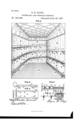
- Figure 1 represents a section of ahall fitted with a sliding-hill embodying my invention.
- Fig. 2 is a side view of a toboggan designed for use with the sliding-hill.
- Fig.3 is a'plan or top view of the same.
- Fig. 4 shows an end view of the toboggan and cross section of the tracks or ways.
- Fig. 5 is an end view of a toboggan with the wheels or rollers detach able.
- Fig. 6 is a view showing the friction and running rollers mounted in the same frame.
- A represents the floor; B, the walls; and O, the ceiling of a hall or other building, one end of the same being removed.
- D D represent the sliding-hill, only one end of whichis shown. The other end connects the several successive stages or spirals.
- brackets E E may be supported by pillars or by rods secured to the ceiling or, should it be desired to erect one out of doors it may be supported upon.
- any suitable form of frame, the means or method of supporting the hill varying according to taste and circumstances.
- F is an elevator-well provided with doors or openings ff.
- the obj eet of this well is that when a person has run from the top of the hill to the bottom both he and his toboggan can be raised for another descent.
- the toboggan G (shown in Figs. 2 and 3) is provided on its under side with wheels or rollers H H.
- wheels or rollers H H In' this case I have shown four rollers; butif they are made wider, then only two need be employed, one at each end. Or, instead of having the rollers on the toboggan, they may be secured to the bottom of the tracks or ways. so as to stand above them, as
- toboggan I On the sides of the toboggan I secure friction-rollers I I, two on each side.
- the object of these rollers is to keep the toboggan in po-' sition in the tracks or ways, (see Fig. 4,) and should the toboggan incline more to one side than the other the friction-rollers willcorne into contact with the sides d of the ways d and prevent the toboggan being retarded by friction.
- v r v I prefer to mount both the running wheels or rollers H and thefriction-rollers I in one and the same frame, K, made of an L form, as shown in Fig. 6, and secured to the toboggan by a bolt passing up through the bottom and two screws passing through the sides.
- the guard or hand rail h On the top of the toboggan is the usual guard or hand rail h.
- a flight of steps may be provided for the riders to ascend to the top of the hill, and the toboggans may be raised by means of an endless chain or rope driven by power, or they may be raised in any suitable and desired manner.
- the hill maybe formed in sections, so that it can be taken apart and moved from place to place.
- a sliding-hill constructed in spiral form and provided with two or more tracks or ways, substantially as shown and described.
Landscapes
- Floor Finish (AREA)
Description
(No Model.)
B. B. FLOYD.
, SLIDING HILL AND TOBOIGGAN THEREFOR. No. 367,286. Patented July 26, 1887,
FIG.]..
UNITED STATES PATENT OFFICE.
BYRON B. FLOYD, OF HAVERHILL, MASSACHUSETTS, ASSIGNOR OF ONE- HALF TO STEPHEN E. J AOKMAN, OF SAME PLACE,
SLIDING-HILL AND TOBOGGAN THEREFOR.
SPECIFICATION forming part of Letters Patent No. 367,286, dated July 26, 1887i 7 Application filed January 20, 1887. Serial No. 224,952. (No model.)
To all whom it may concern: I
Be it known. that I,BYRON B. FLOYD, a citizen of the United States, residing at Haverhill, in the county of Essex and State of Mas sachusetts, have invented certain new and useful Improvements in Sliding-Hills and in Toboggans to be used therewith, of which the following is a specification.-
The object of my invent-ion is to produce a sliding hill particularly adapted for halls,
rinks, and such like places, and in toboggans.
to be used therewith.
The invention consists in constructing the hill in a spiral form and terminating at a point immediately below the starting-point, so that a very long slide may be obtained in a comparatively small space, the hill being provided with tracks or ways; and the invention further consists in constructing toboggans to adapt them to run in or on the said tracks or ways.
Referring to the accompanying drawings, Figure 1 represents a section of ahall fitted with a sliding-hill embodying my invention. Fig. 2 is a side view of a toboggan designed for use with the sliding-hill. Fig.3 is a'plan or top view of the same. Fig. 4 shows an end view of the toboggan and cross section of the tracks or ways. Fig. 5 is an end view of a toboggan with the wheels or rollers detach able.
Fig. 6 is a view showing the friction and running rollers mounted in the same frame.
A represents the floor; B, the walls; and O, the ceiling of a hall or other building, one end of the same being removed.
D D represent the sliding-hill, only one end of whichis shown. The other end connects the several successive stages or spirals.
In the drawings I have shown the slidinghill supported by brackets E E; but it may be supported by pillars or by rods secured to the ceiling or, should it be desired to erect one out of doors it may be supported upon. any suitable form of frame, the means or method of supporting the hill varying according to taste and circumstances.
F is an elevator-well provided with doors or openings ff. The obj eet of this well is that when a person has run from the top of the hill to the bottom both he and his toboggan can be raised for another descent.
I prefer to make the hill with two or more ways or tracks, d (I, so that more than one toboggan can run at the same time without fear of collision.
' The toboggan G (shown in Figs. 2 and 3) is provided on its under side with wheels or rollers H H. In' this case I have shown four rollers; butif they are made wider, then only two need be employed, one at each end. Or, instead of having the rollers on the toboggan, they may be secured to the bottom of the tracks or ways. so as to stand above them, as
shown at d in Fig. 4, or let in so that their periphery will stand just above the bottom of the tracks or ways. In this case the bottom of the toboggans will be fiat without rollers.
On the sides of the toboggan I secure friction-rollers I I, two on each side. The object of these rollers is to keep the toboggan in po-' sition in the tracks or ways, (see Fig. 4,) and should the toboggan incline more to one side than the other the friction-rollers willcorne into contact with the sides d of the ways d and prevent the toboggan being retarded by friction. v r v I prefer to mount both the running wheels or rollers H and thefriction-rollers I in one and the same frame, K, made of an L form, as shown in Fig. 6, and secured to the toboggan by a bolt passing up through the bottom and two screws passing through the sides.
On the top of the toboggan is the usual guard or hand rail h.
In- Fig. 5 the wheels or rollers H H are shown mounted in a saddle with a screw-bolt attached thereto, the bolt passing up through the bottom of the toboggan and secured by a thumbnut, so that they may be readily removed, if required.
Instead of, or in addition to, an elevator a flight of steps may be provided for the riders to ascend to the top of the hill, and the toboggans may be raised by means of an endless chain or rope driven by power, or they may be raised in any suitable and desired manner.
When a rider starts, he first passes down that portion of the track marked 1, along the side marked 2, across the third section of the. track (not shown in the drawings) onto the side 4, thence across the end 5, and along the side 6, onto the seventh section of the track, (not shown,) onto the side 8, and then across the end 9, and along the side 10, and across the eleventh section of the track (not shown) onto the side 12, thence to the elevator or end of the track.
It will be seen from the above that a very long Slide can be obtained in a comparatively smallhall. Thus if the hall is, say, one hundred feet long by fifty feet wide, and has a hill with the number of spirals shown and described, the length of the hill would be about nine hundred feet. Of course, the length of the hillwill depend upon the length, width, and
number of spirals employed, as I do not limit myself to any number, as they will have to be governed by height and the required pitch or inclination given to the hill.
If desired,the hill maybe formed in sections, so that it can be taken apart and moved from place to place.
What I claim as my invention is- 1. A slidinghill constructed in spiral form and terminating at a point immediately below the starting-point, substantially as shown and described.
2. A sliding-hill constructed in spiral form and provided with two or more tracks or ways, substantially as shown and described.
In testimony whereof I have signed my name to this specification in the presence of two subscribing witnesses.
BYRON B. FLOYD.
Witnesses:
J ,mrns M. DAVIS, l G150. W'. W ENTWORTH.
Publications (1)
| Publication Number | Publication Date |
|---|---|
| US367286A true US367286A (en) | 1887-07-26 |
Family
ID=2436304
Family Applications (1)
| Application Number | Title | Priority Date | Filing Date |
|---|---|---|---|
| US367286D Expired - Lifetime US367286A (en) | Half to stephen e |
Country Status (1)
| Country | Link |
|---|---|
| US (1) | US367286A (en) |
Cited By (2)
| Publication number | Priority date | Publication date | Assignee | Title |
|---|---|---|---|---|
| US2487878A (en) * | 1947-07-29 | 1949-11-15 | Oscar E Kantenwein | Stationary connector for termini of angularly disposed conveyers |
| US3625533A (en) * | 1969-09-15 | 1971-12-07 | Richard Boe | Easily carried tobogganlike structure |
-
0
- US US367286D patent/US367286A/en not_active Expired - Lifetime
Cited By (2)
| Publication number | Priority date | Publication date | Assignee | Title |
|---|---|---|---|---|
| US2487878A (en) * | 1947-07-29 | 1949-11-15 | Oscar E Kantenwein | Stationary connector for termini of angularly disposed conveyers |
| US3625533A (en) * | 1969-09-15 | 1971-12-07 | Richard Boe | Easily carried tobogganlike structure |
Similar Documents
| Publication | Publication Date | Title |
|---|---|---|
| US540715A (en) | Coasting apparatus | |
| US2888182A (en) | Variable pitch stairs | |
| US367286A (en) | Half to stephen e | |
| US617779A (en) | Elevator | |
| US20040050654A1 (en) | Escalator for negotiating curves | |
| US807565A (en) | Conveyer. | |
| US850136A (en) | Amusement riding device. | |
| US755361A (en) | Elevator. | |
| US318025A (en) | Artificial coasting or sledding course | |
| US481565A (en) | John a | |
| US25076A (en) | Nathan ames | |
| US807564A (en) | Conveyer. | |
| Zrnić et al. | First Escalators and Their Inventors Until the End of the 19th Century | |
| US363914A (en) | Lebbeus h | |
| US1014856A (en) | Elevator. | |
| US1096826A (en) | Auditorium or hall for buildings. | |
| US469751A (en) | Charles ii | |
| US470918A (en) | Endless conveyor ob elevator | |
| US569539A (en) | George p | |
| US468792A (en) | critchlow | |
| US598772A (en) | Moving stairway | |
| US837890A (en) | Carousel. | |
| US836172A (en) | Stair. | |
| US651241A (en) | Endless-belt conveyer. | |
| US727221A (en) | Curved momentum gravity-track. |