US364984A - barnard - Google Patents
barnard Download PDFInfo
- Publication number
- US364984A US364984A US364984DA US364984A US 364984 A US364984 A US 364984A US 364984D A US364984D A US 364984DA US 364984 A US364984 A US 364984A
- Authority
- US
- United States
- Prior art keywords
- rolls
- belt
- frame
- pulley
- shaft
- Prior art date
- Legal status (The legal status is an assumption and is not a legal conclusion. Google has not performed a legal analysis and makes no representation as to the accuracy of the status listed.)
- Expired - Lifetime
Links
- 230000004048 modification Effects 0.000 description 6
- 238000006011 modification reaction Methods 0.000 description 6
- 230000002441 reversible Effects 0.000 description 6
- 238000010276 construction Methods 0.000 description 2
- 230000000875 corresponding Effects 0.000 description 2
- 230000000994 depressed Effects 0.000 description 2
- OYFJQPXVCSSHAI-QFPUQLAESA-N enalapril maleate Chemical compound OC(=O)\C=C/C(O)=O.C([C@@H](C(=O)OCC)N[C@@H](C)C(=O)N1[C@@H](CCC1)C(O)=O)CC1=CC=CC=C1 OYFJQPXVCSSHAI-QFPUQLAESA-N 0.000 description 2
- 239000000463 material Substances 0.000 description 2
- 230000036633 rest Effects 0.000 description 2
- 239000011435 rock Substances 0.000 description 2
Images

Classifications
-
- B—PERFORMING OPERATIONS; TRANSPORTING
- B02—CRUSHING, PULVERISING, OR DISINTEGRATING; PREPARATORY TREATMENT OF GRAIN FOR MILLING
- B02C—CRUSHING, PULVERISING, OR DISINTEGRATING IN GENERAL; MILLING GRAIN
- B02C4/00—Crushing or disintegrating by roller mills
- B02C4/28—Details
- B02C4/30—Shape or construction of rollers
Definitions
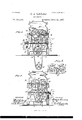
- FIG. 1 represents an elevation of one side
- Fig. 2 is an elevation of the opposite side of the machine.
- Fig. 3 is an elevation of the side of the machine shown in Fig. l, but with the rollers, pulleys, and belttightening mechanism reversed laterally.
- Fig. 4 is an elevation of the side of the machine opposite that shown in Fig.
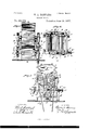
- Fig. 5 is an end elevation of the machine.
- Fig. 6 is a plan view of the rolls and attachments.
- Fig. 7 is an end elevation of a modification of the machine.
- Fig. 8 is a side elevation in detail of the bearings of the rolls.
- the invention relates to improvements in roller-mills, and pertains especially to the beltdrive of the same.
- the rolls are all constructed alike, are interchangeable, and the shaft ofeach is extended at one end to receive a pulley.
- the rolls are arranged in pairs, and may have any kind of dress, preferably V-shaped, the members of each pair having the extended ends of the shafts and pulleys thereon on opposite sides of the machine. They are so placed upon the main frame of the machine that the extended end of the shaft of the fast-running roll of one pair and the similar end of the shaft of the slowrunning roll of the other pair are on the same side of the machine.
- the rolls of each pair turn toward each other, the material to be ground passing between them.
- the bearings are all of equal size and similar, so that thejournals of each roll will fit in any of the bearings.
- An idler or tightening pulley is journaled in a detachable frame, that can be secured in corresponding positions to either leg on the same side of the machine.
- A designates the casing or housing of the mill, having at top the hoppers (L a to feed the rolls, and supported by the heavy frame A, bolted through openings in lugs on the end of itslegs to the floor, as shown in Figs. 1, 2, and 3.
- the frame A is symmetrical, the ends having similar shapes, and in its upper portion, where it connects with the casing A, are the bearings for the rol'l-journals.
- the upper portion of the said casing or housing A is detacL- ably secured to the frame A, so that it may be lifted therefrom to interchange the rolls in their bearings.
- B I3 and O C are the two pairs of rolls,having the extended ends of their shafts journaled in the bearing-blocks b b and c c, respectively.
- the long ends of the shafts of the rolls B B have secured upon them the pulleysDD, of unequal diameters, and the long ends of the shafts of the rolls 0 C have secured upon them the pulleys E E, of diameters. respectively, equal to those of the pulleys D D.
- the pulleys D and E are respectively larger than the pulleys D and E.
- F F are pulleys of equal diameters, on the opposite ends of the transverse counter-shaft f, journaledin thelowerpart ofthcmainframeA.
- G is the main driving-belt, passing around the pulley G on the actuating-shaft g, situated below the tloor X, Fig. 1.
- the said belt passes up through one of the openings at in the floor and over the pulley D, thence down under the pulley F, thence over the pulley E, and thence down through the other opening or to its starting-point from the pulley G.
- H is a belt on the opposite side of the ma- 1 the rolls B 0, thus forming, with the latter, two pairs of grinding-rolls. If the driving In conse- 9 keep the screw 13 and the frame I depressed,
- the casing A is detached and the roll B removed from its bearings and placed in the bearings of the roll 0, the latter being placed in the bearings of the roll 13.
- the rolls B and C are similarly interchanged in their bearings. This adapts the mill to the changed direction of motion of the main shaft and driving-belt, when the former has its rotation reversed.
- the frame I is a rectangular frame, pivoted at one end to a pin or arm, i, standing out from the upper end of one leg of the frame A on the same side of the belt H.
- the frame I surrounds the belt H, and has journaled transversely upon it the idler-pulley I, hereinbefore referred to, and under which the said belt passes.
- the end of the frame I, opposite the pivoted end, has passing through a threaded opening in it the upper end of a vertical adjustingscrew, i, a proper nut being on said screw above the frame.
- the said screw z" passes through-an opening in a lug, 6 standing out from an extension of the frameA, and has between the lower surface of said lug and its head i the coiled spring 13*, which tends to so that the idler 1 will always keep the belt J is an arm pivoted at its lower end at a proper point on a boss, y, on one leg of the main frame, on the same side as the belt G, and carrying an idler-pulley, J, with its shaft journaled in the bifurcated upper end thereof.
- j is a nut pivoted in an opening in the arm J below said bifurcation.
- the 7c is a longitudinal rod passing through a lug, K, on the leg of the main frame A, on the same side but opposite end to that on which the arm J is attached.
- the inner end of the rod 7c is threaded, to engage the pivoted nut in the opening of the arm J.
- the said rod passes loosely through the lug K, and has surrounding it, between said lug and its head 70, the coiled spring 70 which tendsto force it outward and to draw the idler J against the belt-G,on which it rests, so as to keep the said belt suiiic'iently taut.
- the arm J is detachable from its boss'y, and can 'be attached to a similar boss, g, on the opposite leg, but the same side of the frame A, the same pin, y serving to attach it to each boss.
- the said pin passes through an opening in the enlarged end of the arm J, and enters the opening of either boss where it is secured.
- the rod is also reversible bypassing it through an open- 7 ing in a lug, K ,carrespanding to the lug K,
- FIG. 7 shows a modification of the belttightening devices, the arms J in this case being pivoted upon the lower part of the main frame at the points 3 or 1 while the rod 70 is shorter and reversible, as before.
- This construction is used on machines in which it is not possible nor desirable to use the former modification.
- a roller-mill comprising the following instrumentalities: main frame A, provided with devices for'supporting a belt-tightening frame on each side of the main drivingbelt, o
Description
(No Model.) 3 Sheets-Sheet 1.
H. A. BARNARD.
ROLLER MILL.
No. 864,984. n atented June 14, 1887.
T'VITW'ESSES ROLLER MILL.
No. 364,984. Patented June 14, 1887.
H. A. BARNARD.
ROLLER MILL.
No. 364,984. 02/ Patented June 14, 1887.
n Hill mm .of the roller-mill.
HEMAN A. BARNARD, OF MOLINE, ILLINOIS, ASSIGNOR TO THE BARNARD & LEAS MANUFACTURING COMPANY.
ROLLER-MILL.
SPECIFICATION forming part of Letters Patent No. 364,984, dated June 14, 1887.
Application tiled .\pril 21, [886.
To all whom, it may concern.-
Be it known that I, IIEMAN A. BARNARD, of Moline, .in the county of Rock Island and State of Illinois, have invented certain new and useful Improvements in Roller-Mills; and I do hereby declare that the following is a full, clear, and exact description thereof, reference being had to the accompanying drawings, and to the letters of reference marked thereon, which form part ofthisspceitication,in which Figure 1 represents an elevation of one side Fig. 2 is an elevation of the opposite side of the machine. Fig. 3 is an elevation of the side of the machine shown in Fig. l, but with the rollers, pulleys, and belttightening mechanism reversed laterally. Fig. 4 is an elevation of the side of the machine opposite that shown in Fig. 3, with the rolls in the same position. Fig. 5 is an end elevation of the machine. Fig. 6 is a plan view of the rolls and attachments. Fig. 7 is an end elevation of a modification of the machine. Fig. 8 is a side elevation in detail of the bearings of the rolls.
The invention relates to improvements in roller-mills, and pertains especially to the beltdrive of the same.
The rolls are all constructed alike, are interchangeable, and the shaft ofeach is extended at one end to receive a pulley. The rolls are arranged in pairs, and may have any kind of dress, preferably V-shaped, the members of each pair having the extended ends of the shafts and pulleys thereon on opposite sides of the machine. They are so placed upon the main frame of the machine that the extended end of the shaft of the fast-running roll of one pair and the similar end of the shaft of the slowrunning roll of the other pair are on the same side of the machine. The rolls of each pair turn toward each other, the material to be ground passing between them. The bearings are all of equal size and similar, so that thejournals of each roll will fit in any of the bearings. An idler or tightening pulley is journaled in a detachable frame, that can be secured in corresponding positions to either leg on the same side of the machine.
The objects of making the rolls interchangeable and the tightening-pulley reversible to either side of the main driving-belt is to adapt Serial No. 190.675. (No model.)
the mill to the motion of the driving-shaft when turning in either direction.
Referring to the accompanying drawings, A designates the casing or housing of the mill, having at top the hoppers (L a to feed the rolls, and supported by the heavy frame A, bolted through openings in lugs on the end of itslegs to the floor, as shown in Figs. 1, 2, and 3.
The frame A is symmetrical, the ends having similar shapes, and in its upper portion, where it connects with the casing A, are the bearings for the rol'l-journals. The upper portion of the said casing or housing A is detacL- ably secured to the frame A, so that it may be lifted therefrom to interchange the rolls in their bearings.
B I3 and O C are the two pairs of rolls,having the extended ends of their shafts journaled in the bearing-blocks b b and c c, respectively. The long ends of the shafts of the rolls B B have secured upon them the pulleysDD, of unequal diameters, and the long ends of the shafts of the rolls 0 C have secured upon them the pulleys E E, of diameters. respectively, equal to those of the pulleys D D. The pulleys D and E are respectively larger than the pulleys D and E.
F F are pulleys of equal diameters, on the opposite ends of the transverse counter-shaft f, journaledin thelowerpart ofthcmainframeA.
G is the main driving-belt, passing around the pulley G on the actuating-shaft g, situated below the tloor X, Fig. 1. The said belt passes up through one of the openings at in the floor and over the pulley D, thence down under the pulley F, thence over the pulley E, and thence down through the other opening or to its starting-point from the pulley G.
H is a belt on the opposite side of the ma- 1 the rolls B 0, thus forming, with the latter, two pairs of grinding-rolls. If the driving In conse- 9 keep the screw 13 and the frame I depressed,
.H taut.
shaft should have its motion reversed,'in order to prevent crossing the belts, the casing A is detached and the roll B removed from its bearings and placed in the bearings of the roll 0, the latter being placed in the bearings of the roll 13. The rolls B and C are similarly interchanged in their bearings. This adapts the mill to the changed direction of motion of the main shaft and driving-belt, when the former has its rotation reversed.
Iis a rectangular frame, pivoted at one end to a pin or arm, i, standing out from the upper end of one leg of the frame A on the same side of the belt H. The frame I surrounds the belt H, and has journaled transversely upon it the idler-pulley I, hereinbefore referred to, and under which the said belt passes. The end of the frame I, opposite the pivoted end, has passing through a threaded opening in it the upper end of a vertical adjustingscrew, i, a proper nut being on said screw above the frame. The said screw z" passes through-an opening in a lug, 6 standing out from an extension of the frameA, and has between the lower surface of said lug and its head i the coiled spring 13*, which tends to so that the idler 1 will always keep the belt J is an arm pivoted at its lower end at a proper point on a boss, y, on one leg of the main frame, on the same side as the belt G, and carrying an idler-pulley, J, with its shaft journaled in the bifurcated upper end thereof.
j is a nut pivoted in an opening in the arm J below said bifurcation.
7c is a longitudinal rod passing through a lug, K, on the leg of the main frame A, on the same side but opposite end to that on which the arm J is attached. The inner end of the rod 7c is threaded, to engage the pivoted nut in the opening of the arm J. The said rod passes loosely through the lug K, and has surrounding it, between said lug and its head 70, the coiled spring 70 which tendsto force it outward and to draw the idler J against the belt-G,on which it rests, so as to keep the said belt suiiic'iently taut. The arm J is detachable from its boss'y, and can 'be attached to a similar boss, g, on the opposite leg, but the same side of the frame A, the same pin, y serving to attach it to each boss. The said pin passes through an opening in the enlarged end of the arm J, and enters the opening of either boss where it is secured. The rod is is also reversible bypassing it through an open- 7 ing in a lug, K ,carrespanding to the lug K,
and at a similar point on the opposite leg. The arm and rod are thus reversed when the rolls are interchanged in their bearings, as
described.
- Fig. 7 shows a modification of the belttightening devices, the arms J in this case being pivoted upon the lower part of the main frame at the points 3 or 1 while the rod 70 is shorter and reversible, as before. This construction is used on machines in which it is not possible nor desirable to use the former modification.
Having described my invention, what I claim, and desire to secure by Letters Patent, is
1. In a four-roller mill, the combination; with the interchangeable rolls provided with pulleys,ofa main driving-shaft having a pulley 7 thereon, a counter-shaft having a pulley on each end, a main driving-belt communicating power from said shaft to the pulleys on one roll of each pair on the same side of the ma chine and to said counter-shaft, a belt on the opposite side of the machine transmitting motion from the counter-shaft to the remaining rolls of the machine, a belt-tightening device,- and an adjustable and'detachable frame therefor, all constructed and arranged to operate substantially as and for the purpose set forth.
2. A roller-mill comprising the following instrumentalities: main frame A, provided with devices for'supporting a belt-tightening frame on each side of the main drivingbelt, o
bearing-blocks b bc c, interchangeable rolls B B G G, pulleys D D E EF F, countershaftf, main driving-belt G, and belt-tightening pulley J for said belt, a detachable and adjustable frame for said pulley, and short 5 1) b c c, interchangeable rolls B B O O, coun- 10.0
fer-shaft f, pulleys D D, E E, and F F, belts G H, idler-pulley I, frame I, adjust-ingrodsi 7c, tightening-pulley J, and detachablypivoted arm J, all constructed and arranged to operate substantially as and for the purpose set forth.
In testimony thatIclaim the foregoing as my own I affix my signature in presence of two witnesses.
HEMAN A. BARNARD.
Witnesses:
J. S. LEAS, Geo. M. FARNUM.
Publications (1)
| Publication Number | Publication Date |
|---|---|
| US364984A true US364984A (en) | 1887-06-14 |
Family
ID=2434010
Family Applications (1)
| Application Number | Title | Priority Date | Filing Date |
|---|---|---|---|
| US364984D Expired - Lifetime US364984A (en) | barnard |
Country Status (1)
| Country | Link |
|---|---|
| US (1) | US364984A (en) |
Cited By (1)
| Publication number | Priority date | Publication date | Assignee | Title |
|---|---|---|---|---|
| US4116390A (en) * | 1975-02-14 | 1978-09-26 | Uhde Gmbh | Process for reducing the grain size of phosphate rock |
-
0
- US US364984D patent/US364984A/en not_active Expired - Lifetime
Cited By (1)
| Publication number | Priority date | Publication date | Assignee | Title |
|---|---|---|---|---|
| US4116390A (en) * | 1975-02-14 | 1978-09-26 | Uhde Gmbh | Process for reducing the grain size of phosphate rock |
Similar Documents
| Publication | Publication Date | Title |
|---|---|---|
| US364984A (en) | barnard | |
| US188569A (en) | Improvement in machines for pointing sewing-machine needles | |
| US643637A (en) | Feed-mill. | |
| US382583A (en) | barnard | |
| US138873A (en) | Improvement in horse-powers | |
| US784165A (en) | Machinery or apparatus for skiving leather, leather-board, &c. | |
| US2905396A (en) | Triple roll crusher | |
| US414754A (en) | Seam-pressing machine | |
| US613676A (en) | Corn-shredded | |
| US403109A (en) | Feed device for wire-weaving machines | |
| US299789A (en) | Roller-mill | |
| US382587A (en) | brimold | |
| US441633A (en) | Vibrator attachment for polishing-machines | |
| US466048A (en) | Curd grinder | |
| US263906A (en) | Noah w | |
| USRE15179E (en) | Bock-crttsheb | |
| US393681A (en) | Three-roller mill | |
| US453376A (en) | Method of adjusting grinding-rolls | |
| US298206A (en) | Eollee mill | |
| US468436A (en) | Paper-polishing machine | |
| US359659A (en) | Crushing and grinding mill | |
| US799715A (en) | Dough-breaker. | |
| US267556A (en) | mechwaet | |
| US864502A (en) | Pulverizing-machine. | |
| US241397A (en) | mechwabt |