US3633453A - Percussion musical instrument and tone bar therefor - Google Patents
Percussion musical instrument and tone bar therefor Download PDFInfo
- Publication number
- US3633453A US3633453A US56607A US5660770A US3633453A US 3633453 A US3633453 A US 3633453A US 56607 A US56607 A US 56607A US 5660770 A US5660770 A US 5660770A US 3633453 A US3633453 A US 3633453A
- Authority
- US
- United States
- Prior art keywords
- bar
- tone
- clip
- nodal
- spaced
- Prior art date
- Legal status (The legal status is an assumption and is not a legal conclusion. Google has not performed a legal analysis and makes no representation as to the accuracy of the status listed.)
- Expired - Lifetime
Links
Images

Classifications
-
- G—PHYSICS
- G10—MUSICAL INSTRUMENTS; ACOUSTICS
- G10D—STRINGED MUSICAL INSTRUMENTS; WIND MUSICAL INSTRUMENTS; ACCORDIONS OR CONCERTINAS; PERCUSSION MUSICAL INSTRUMENTS; AEOLIAN HARPS; SINGING-FLAME MUSICAL INSTRUMENTS; MUSICAL INSTRUMENTS NOT OTHERWISE PROVIDED FOR
- G10D13/00—Percussion musical instruments; Details or accessories therefor
- G10D13/01—General design of percussion musical instruments
- G10D13/08—Multi-toned musical instruments with sonorous bars, blocks, forks, gongs, plates, rods or teeth
-
- G—PHYSICS
- G10—MUSICAL INSTRUMENTS; ACOUSTICS
- G10K—SOUND-PRODUCING DEVICES; METHODS OR DEVICES FOR PROTECTING AGAINST, OR FOR DAMPING, NOISE OR OTHER ACOUSTIC WAVES IN GENERAL; ACOUSTICS NOT OTHERWISE PROVIDED FOR
- G10K1/00—Devices in which sound is produced by striking a resonating body, e.g. bells, chimes or gongs
- G10K1/06—Devices in which sound is produced by striking a resonating body, e.g. bells, chimes or gongs the resonating devices having the shape of a bell, plate, rod, or tube
- G10K1/08—Details or accessories of general applicability
- G10K1/10—Sounding members; Mounting thereof; Clappers or other strikers
Definitions
- the tone bar is held by the clips against undesired movement with respect to the supports.
- the clips are normally located adjacent to the nodal points on the ends of the tone bar, remote from the center region thereof.
- the tone bar supports comprise elastomeric mounts through which the clips extend, and which are frictionally mounted on cylindrical support posts.
- tone bars for the production of specific notes.
- Practically all of such tone bars are and have been barlike structures formed out of a rigid or relatively rigid material such as various types of hardwoods, steel and aluminum alloys or the like.
- tone bars formed of such materials When tone bars formed of such materials are excited, as by being struck with mallets, they vibrate and give off notes or sounds which are dependent upon a number of factors. The most important of these factors are the physical dimensions of the tone bars themselves, and the manners in which the tone bars are supported.
- the above-described manner of vibration is important in order to obtain a tonal quality of a desired character. It is believed that the physical character of the tone bar itself is also important to obtaining this desired manner of vibration. It has also been recognized that the manner in which a tone bar is mounted can significantly determine such tonal qualities. Thus, for example, when a tone bar is mounted by a cord extending through horizontal holes in the bar, at the nodal regions thereof, the mere presence of such holes alters the physical character of the bar and afi'ects the manner in which it can vibrate. Similar results are achieved when vertically extending mounting holes are bored through tone bars at about the nodal areas thereof.
- the manufacture of the tone bars has been a significant economic problem. Because of the above-described effects of horizontally extending holes on such tone bars, it has been conventional to remove material from the tone bars, in a laborious and complicated manner, to tune them so that they vibrate at a desired frequency. When vertically extending holes have been used, the tuning process has been similarly complicated and it has frequently been necessary to tune such tone bars by removing material therefrom. Such removal of material is expensive and wasteful. It is also believed to tend to result in a loss of tone quality.
- An object of this invention is to provide a new and improved percussion musical instrument incorporating tone bars which include means for attaching these tone bars to a support. Another object is to provide tone bars which may be easily and conveniently manufactured at a comparatively nominal cost. A further objective of this invention is to provide tone bars which have highly acceptable tonal qualities.
- a percussion musical instrument incorporating tone bars, each of which includes clip means for attaching the bar to supports at nodal areas intermediate the ends of the bar.
- Such clip means are attached to the undersurface of each tone bar on the sides of the nodal areas towards the ends of the tone bar.
- Each of the clip means includes means engaging a support for the tone bar in such manner that such a support directly contacts the tone bar at a nodal area.
- the clip means serves, as one of its functions, to prevent undesired movement of the tone bar with respect to the support.
- the support is an elastomeric mount through which the clip means extends, such mount being supported on posts which project into the mount base.
- FIG. I is a side elevational view illustrating a first embodiment of the invention.
- FIG. 2 is a partial bottom isometric view of the tone bar shown in FIG. 1;
- FIG. 3 is a side elevational view corresponding to FIG. 1 but showing a second embodiment of the invention
- FIG. 4 is a partial bottom isometric view of the tone bar shown in FIG. 3;
- FIG. 5 is an isometric view of a support member used with the tone bar shown in FIG. 3;
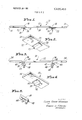
- FIG. 6 is an exploded isometric view showing a third embodiment of the invention, portions being broken away and sectioned in order to illustrate the structure more clearly;
- FIG. 7 is a fragmentary end view illustrating such third embodiment in assembled condition, the end illustrated being the one to the left in FIG. 6;
- FIG. 8 is a sectional view on the broken line 8-8 of FIG. 7;
- FIG. 9 is a side elevational view of a fourth embodiment, wherein a mechanical-electrical transducer is provided to sense the vibrations of the tone bar.
- FIGS. I and 2 there is shown a complete tone bar 10 of this invention.
- This complete tone bar l0 includes an elongated bar. 12 of a rigid material such as a conventional steel alloy of the type commonly employed in the tone bar of a percussive-type musical instrument.
- Bar 12 is preferably of a uniform cross-sectional configuration throughout its length between the ends 14.
- the bar 12 is adapted to be mounted in such instrument (at what may be referred to as nodal areas 16 extending across the width of bar 12 intermediate its ends 14) by conventional cord-type supports 18.
- These supports I8 are held in place by identically formed clips 20, each of which includes a base 22 attached to a lower surface 24 of the bar l2.
- the clips 20 are made out of a composition which will enable the bases 22 to be welded to the bar 12.
- a composition may be a steel composition when the bar 12 is a steel bar.
- the bases 22 of the clip 20 can be attached to the bar 12 in other manners as for example through the use of a small quantity of an appropriate conventional adhesive. This is advantageous when the bar 12 or the clips 20 are formed of a material which cannot be conveniently welded.
- Each of the clips 20 includes a curved hooklike end 26 which wraps around and engages the surface of a support 18 in such manner that such a support 18 cannot be moved relative to the ends 14 of the bar 12. It will be noted that hooklike ends 26 terminate so as to be spaced from the bar 12. These ends 26 extend from the bases 22 of the clips 20 as shown.
- the bar 12 is cut from conventional bar stock of an appropriate material so that when supported on supports such as the supports 18 it will vibrate (when excited as by the application of a mallet) at a frequency which is slightly more than the desired frequency at which this bar 12 is to vibrate in an ultimate instrument. Then the clips 20 are applied and attached to this bar as shown. The weight of these clips is determined prior to their attachment, by experimentation, to be sufficient so that when they are applied as shown, equidistant from the ends 14 of the bar 12, the bar 12 will vibrate in the complete bar at the above-indicated desired frequency (in the ultimate instrument).
- the clips and the bars 12 used in manufacturing the complete tone bar 10 can be easily predetermined so that complete tone bars 10 manufactured on essentially a mass production basis will not require further tuning. This is a major benefit resulting in significant cost savings over prior procedures. Also, the actual manufacturing methods which may be employed are comparatively inexpensive.
- the bar 12 used in the complete bar 10 is not physically altered as by the drilling of holes therethrough, it will tend to vibrate comparatively accurately so that the ends 14 vibrate in two half-loops and so that the center portion between the supports 18 will vibrate as substantially two half-loops when the bar 12 is excited.
- the term loops here refers to the manner of vibration at the intended vibration frequency. With this structure, the nodal areas 16 will tend to be substantially straight lines extending directly across a bar such as the bar 12.
- the structure described has another advantage as far as a percussive-type musical instrument is concerned.
- the individual clips 20 to a degree act as weights tending to prolongate the decay time of vibration of the complete bar 10 after excitation. This is advantageous, particularly in certain types of instruments. This result achieved with this invention should be compared with the fact that holes through a tone bar tend, in general, to diminish the decay time of the vibration of such a bar.
- This tone bar 30 utilizes a bar 32 corresponding to the bar 12, and having ends 34 and nodal areas 36. These nodal areas are, of course, of the same type as the areas 16.
- identical clips 38 are used.
- Each of these clips 38 includes a base 40, corresponding to a base 22 previously described, and a projection 42.
- the bases 40 are adapted to be attached to the bar 32 in the same manner as previously described.
- the projections 42 are adapted to fit within slots 44 in elastomeric mounts 46 so that the bar 32 is supported along edges 48 of these mounts 46. Such edges 48 extend along the nodal areas 36. With this construction, the clips 38 satisfactorily engage the mounts 46 so that a complete tone bar 30 is held in desired orientation when the mounts 46 are secured in place in any convenient manner.
- an elongated metal bar 50 of rectangular shape and section, has welded to the undersurface thereof a pair of identical clips 51, thus forming a tone bar for the percussion musical instrument.
- the welding is preferably effected by electrical resistance spot welding.
- the bar 50 is free of holes.
- the clips 51 are so located that the bar 50 will be supported, by support means described below, at nodal areas 52 which extend perpendicularly to the longitudinal bar axis (and lie in the plane of the bar).
- the clips 51 are spaced equal distances from the ends of bar 50.
- each clip 51 comprises a base 53 which is in flatwise engagement with the lower surface of bar 50.
- Such base 53 is spot welded to bar 50 at a region between the adjacent bar end and the nodal area 52.
- Base 53 is integral with a distal portion in the form of a hook 54 which curves downwardly (away from bar 50) and then upwardly.
- the end 55 of the hook is spaced from the lower surface of bar 50 a distance substantially less than the diameter of a horizontal cylinder 56 forming part of an elastomeric mount 57 for each end of the tone bar.
- Such distance is. however, sufficiently great that cylinder 56 may be distorted and snapped between end 55 and the tone bar surface, thus locking the cylinder 56 is position.
- each elastomeric mount 57 is generally triangularly shaped, having upper rounded edge portions 58 (FIG. 6) which align with and form extensions of the upper half of cylinder 56.
- Mount 57 is also formed with a central slot 59 through which hook 54 extends, such slot being only a small amount wider than the hook to thereby prevent undesired lateral movements of the bar relative to the supports therefor. 7
- each slot 59 has a sufficiently large vertical dimension that the bar 50 (at nodal region 52) will seat on cylinder 56 and also on the adjacent edge portions 58.
- the radius of hook 54 is substantially larger than that of cylinder 56, thus permitting the bar to rebound off cylinder 56 (and off edge portions 58) after the bar is struck, in order to achieve maximum dwell.
- Cylindrical recesses 61 are formed in the underside of the base of each mount 57 in order to receive cylindrical mounting posts 62.
- the diameter of each recess 61 is substantially the same as that of the associated post 62, whereby the mount 57 will remain in position (after being pressed downwardly over the posts) until intentionally removed.
- the posts 62 are mounted on the upper wall of a support 63.
- FIGS. 6-8 is readily assembled by snapping cylinders 56 into clips 54, and then pressing mounts 57 over posts 62.
- the result is a percussion musical instrument adapted to be struck by a mallet to thereby generate a musical tone superior to those generated by prior art instruments.
- the instrument may be struck at any part of the upper surface of bar 50, and still generate a musical tone.
- the quality of the tone is enhanced due to the fact that portions 56 and 58 of each mount 57 are perpendicular to the bar axis, not oblique thereto as in numerous prior art instruments.
- Transducer 71 may be, for example, an electromagnetic pickup comprising a permanent magnet enclosed in a coil of wire, and magnetically coupled to the steel (or steel alloy) bar 50.
- the transducer 71 is connected to an amplifier 72 and loudspeaker 73. Numerous tone control, vibrato, and special effects circuits, not shown, may be provided.
- An elongated tone bar of a rigid material for use in producing a tone of an intended frequency said tone bar including two means for attaching said tone bar to members supporting said tone bar, each of said means being located at a nodal area of said tone bar extending across the width of the bar, said areas being intermediate the ends of said tone bar, wherein the improvement comprises:
- said bar being free of holes so that it will vibrate as a halfloop at each of its ends as defined by said nodal areas and so that it will vibrate accurately as two half-loops in its center portion between said nodal areas,
- each of said means for attaching said tone bar comprises clip means attached to the lower surface of said tone bar on the sides of said nodal areas remote from one another, each of said clip means including means for engaging a member for supporting said tone bar,
- said means for engaging a member on both of said clip means being ends of said clip means, said ends being spaced from said tone bar,
- said clip means being identical and being equally spaced from the ends of said tone bar.
- a tone bar as claimed in claim 1 including two elastomeric mount means for supporting said tone bar, each of said mount means being engaged with one of said ends of said clip means so as to support said tone bar.
- a tone bar as claimed in claim 2 wherein:
- each of said mount means includes an edge which contacts said tone bar, said edges of said mount means engaging said tone bar along said nodal areas.
- a tone bar as claimed in claim 1 including:
- said ends are of a curved hooklike shape and are located so that said cord means are positioned between said ends of said clip means and the nodal areas of said tone bar, said cord means both extending across the width of said tone bar along said nodal areas.
- a percussion musical instrument which comprises:
- said bar adapted to vibrate at a predetermined frequency when the upper surface thereof is struck by an exciting means
- said bar when vibrating having a first nodal area located relatively adjacent one end of said bar but spaced therefrom,
- said bar when vibrating having a second nodal area located relatively adjacent the other end of said bar but spaced therefrom,
- first and second clips each having a base portion and a distal portion
- said base portion of said first clip being secured to the lower surface of said bar adjacent said first nodal area, and in such position that said distal portion of said first clip is spaced from said lower surface of said bar directly opposite said first nodal area,
- said base portion of said second clip being secured to said lower surface of said bar adjacent said second nodal area, and in such position that said distal portion of said second clip is spaced from said lower surface of said bar directly opposite said second nodal area, and
- first and second supports disposed, respectively, between said first nodal area and said distal portion of said first clip, and between said second nodal area and said distal portion of said second clip,
- said supports engaging said lower surface of said bar respectively at said first and second nodal areas.
- each of said clip base portions is disposed in fiatwise engagement with said lower surface of said bar.
- each of said clips is formed of metal, and in which each of said clip base portions is secured to said bar by electrical resistance spot welding.
- each of said clips is generally hook-shaped, the hook extending down from the base portion therefor and then curving upwardly toward said bar for termination at a point spaced from the lower surface of said bar
- each of said supports is an elongated deformable member having a diameter greater than the spacing between said point and said lower surface of said bar, said support being adapted to deform and snap through said space between said point and said lower surface whereby to retain said support in said hookshaped distal portion.
- each of said supports is part of a mount formed of elastomeric material, said mount having a plurality of recesses in the underside thereof, and in which a plurality of mounting posts are provided and extended into said recesses to support each of said mounts.
- each of said supports is a horizontal member formed of elastomeric material, said member having the ends thereof connected with the upper edges of an elastomeric mount, in which said mount has a slot therethrough below said support and through which said distal clip portion extends, and in which said horizontal support member and said upper edges engage said lower surface of said tone bar along a line perpendicular to the axis of said bar and located at one of said nodal areas.
- a percussion musical instrument which comprises:
- said bar being adapted to vibrate at a predetermined frequency when the upper surface thereof is struck by an exciting means
- said bar when vibrating having a first nodal area located relatively adjacent one end of said bar but spaced therefrom,
- said bar when vibrating having a second nodal area located relatively adjacent the other end of said bar but spaced therefrom,
- first and second clip means each having a base portion
- said base portion of said first clip means being secured to the lower surface of said bar adjacent said first nodal area
- each of said first and second clip means also having a portion spaced away from said lower surface of said bar, said spacedaway portion of said first clip means being opposite said first nodal area, said spaced-away portion of said second clip means being opposite said second nodal area, and
- first and second supports disposed, respectively, between said first nodal area and said spaced-away portion of said first clip means, and between said second nodal area and said spaced-away portion of said second clip means,
- said supports engaging said lower surface of said bar respectively at said first and second nodal areas.
- each of said supports is a horizontal member formed of elastomeric material, said member having the ends thereof connected with the upper edges of an elastomeric mount, in which said mount has a slot therethrough below said support and through which said spaced-away portion of the associated clip means extends, and in which said horizontal support member and said upper edges engage said lower surface of said tone bar along a line perpendicular to the axis of said bar and located at one of said nodal areas.
Landscapes
- Physics & Mathematics (AREA)
- Engineering & Computer Science (AREA)
- Acoustics & Sound (AREA)
- Multimedia (AREA)
- Stringed Musical Instruments (AREA)
- Clamps And Clips (AREA)
- Electrophonic Musical Instruments (AREA)
Abstract
Description
Claims (15)
Priority Applications (4)
| Application Number | Priority Date | Filing Date | Title |
|---|---|---|---|
| FR7007389A FR2037468A5 (en) | 1968-08-14 | 1970-03-02 | Tone bars for use in musical instruments. |
| DE19702020564 DE2020564A1 (en) | 1968-08-14 | 1970-04-27 | Ruler for musical instruments |
| GB2388170A GB1250126A (en) | 1968-08-14 | 1970-05-18 | Improvements relating to musical instruments. |
| US56607A US3633453A (en) | 1968-08-14 | 1970-07-20 | Percussion musical instrument and tone bar therefor |
Applications Claiming Priority (5)
| Application Number | Priority Date | Filing Date | Title |
|---|---|---|---|
| US75256168A | 1968-08-14 | 1968-08-14 | |
| FR7007389A FR2037468A5 (en) | 1968-08-14 | 1970-03-02 | Tone bars for use in musical instruments. |
| DE19702020564 DE2020564A1 (en) | 1968-08-14 | 1970-04-27 | Ruler for musical instruments |
| GB2388170A GB1250126A (en) | 1968-08-14 | 1970-05-18 | Improvements relating to musical instruments. |
| US56607A US3633453A (en) | 1968-08-14 | 1970-07-20 | Percussion musical instrument and tone bar therefor |
Publications (1)
| Publication Number | Publication Date |
|---|---|
| US3633453A true US3633453A (en) | 1972-01-11 |
Family
ID=40524523
Family Applications (1)
| Application Number | Title | Priority Date | Filing Date |
|---|---|---|---|
| US56607A Expired - Lifetime US3633453A (en) | 1968-08-14 | 1970-07-20 | Percussion musical instrument and tone bar therefor |
Country Status (4)
| Country | Link |
|---|---|
| US (1) | US3633453A (en) |
| DE (1) | DE2020564A1 (en) |
| FR (1) | FR2037468A5 (en) |
| GB (1) | GB1250126A (en) |
Cited By (10)
| Publication number | Priority date | Publication date | Assignee | Title |
|---|---|---|---|---|
| US3731580A (en) * | 1969-11-28 | 1973-05-08 | Nippon Musical Instruments Mfg | Tone bar fixing structure for a metal tone bar type percussion musical instrument |
| US3872767A (en) * | 1971-11-09 | 1975-03-25 | Musikind Forskning Mifo Ab | Musical instrument with piano keyboard |
| US4373418A (en) * | 1981-01-09 | 1983-02-15 | Cbs Inc. | Tuning fork mounting assembly in electromechanical pianos |
| EP0924686A3 (en) * | 1997-12-19 | 2000-02-23 | Gitre' S.R.L. | Attachment device for sounding bars of musical percussion instruments |
| US6072111A (en) * | 1994-07-30 | 2000-06-06 | Senn; Friedrich | Device for producing at least one sound |
| US6245978B1 (en) | 1999-12-15 | 2001-06-12 | Leigh Howard Stevens | Keyboard musical percussion instrument tone bar suspension |
| US20090211428A1 (en) * | 2005-12-13 | 2009-08-27 | Yamaha Corporation | Tone plate for keyboard-type tone plate percussion instrument, tone plate-fabricating method, tone generator unit of tone plate percussion instrument, and keyboard-type percussion instrument |
| US20170278493A1 (en) * | 2016-03-22 | 2017-09-28 | Yamaha Corporation | Musical instrument |
| WO2020091857A1 (en) * | 2018-10-31 | 2020-05-07 | Glowka John | Electrically amplified marimba |
| US10916228B1 (en) * | 2020-03-31 | 2021-02-09 | Diego Elias | Musical instrument with vibrating rods to generate sound |
Citations (5)
| Publication number | Priority date | Publication date | Assignee | Title |
|---|---|---|---|---|
| US1575960A (en) * | 1923-02-08 | 1926-03-09 | Bar Zim Toy Mfg Co Inc | Xylophone |
| US1664587A (en) * | 1928-04-03 | Piano | ||
| US2317164A (en) * | 1942-10-07 | 1943-04-20 | Zimmerman Harry | Xylophone |
| US2458193A (en) * | 1945-08-11 | 1949-01-04 | Joseph A Packheiser | Xylophone |
| US2504915A (en) * | 1948-10-28 | 1950-04-18 | Zimmerman Harry | Xylophone |
-
1970
- 1970-03-02 FR FR7007389A patent/FR2037468A5/en not_active Expired
- 1970-04-27 DE DE19702020564 patent/DE2020564A1/en active Pending
- 1970-05-18 GB GB2388170A patent/GB1250126A/en not_active Expired
- 1970-07-20 US US56607A patent/US3633453A/en not_active Expired - Lifetime
Patent Citations (5)
| Publication number | Priority date | Publication date | Assignee | Title |
|---|---|---|---|---|
| US1664587A (en) * | 1928-04-03 | Piano | ||
| US1575960A (en) * | 1923-02-08 | 1926-03-09 | Bar Zim Toy Mfg Co Inc | Xylophone |
| US2317164A (en) * | 1942-10-07 | 1943-04-20 | Zimmerman Harry | Xylophone |
| US2458193A (en) * | 1945-08-11 | 1949-01-04 | Joseph A Packheiser | Xylophone |
| US2504915A (en) * | 1948-10-28 | 1950-04-18 | Zimmerman Harry | Xylophone |
Cited By (13)
| Publication number | Priority date | Publication date | Assignee | Title |
|---|---|---|---|---|
| US3731580A (en) * | 1969-11-28 | 1973-05-08 | Nippon Musical Instruments Mfg | Tone bar fixing structure for a metal tone bar type percussion musical instrument |
| US3872767A (en) * | 1971-11-09 | 1975-03-25 | Musikind Forskning Mifo Ab | Musical instrument with piano keyboard |
| US4373418A (en) * | 1981-01-09 | 1983-02-15 | Cbs Inc. | Tuning fork mounting assembly in electromechanical pianos |
| US6072111A (en) * | 1994-07-30 | 2000-06-06 | Senn; Friedrich | Device for producing at least one sound |
| EP0924686A3 (en) * | 1997-12-19 | 2000-02-23 | Gitre' S.R.L. | Attachment device for sounding bars of musical percussion instruments |
| US6245978B1 (en) | 1999-12-15 | 2001-06-12 | Leigh Howard Stevens | Keyboard musical percussion instrument tone bar suspension |
| US20090211428A1 (en) * | 2005-12-13 | 2009-08-27 | Yamaha Corporation | Tone plate for keyboard-type tone plate percussion instrument, tone plate-fabricating method, tone generator unit of tone plate percussion instrument, and keyboard-type percussion instrument |
| US7804014B2 (en) * | 2005-12-13 | 2010-09-28 | Yamaha Corporation | Tone plate for keyboard-type tone plate percussion instrument, tone plate-fabricating method, tone generator unit of tone plate percussion instrument, and keyboard-type percussion instrument |
| US20170278493A1 (en) * | 2016-03-22 | 2017-09-28 | Yamaha Corporation | Musical instrument |
| US10127896B2 (en) * | 2016-03-22 | 2018-11-13 | Yamaha Corporation | Musical instrument |
| WO2020091857A1 (en) * | 2018-10-31 | 2020-05-07 | Glowka John | Electrically amplified marimba |
| US10984773B2 (en) * | 2018-10-31 | 2021-04-20 | John Glowka | Electrically amplified marimba |
| US10916228B1 (en) * | 2020-03-31 | 2021-02-09 | Diego Elias | Musical instrument with vibrating rods to generate sound |
Also Published As
| Publication number | Publication date |
|---|---|
| FR2037468A5 (en) | 1970-12-31 |
| GB1250126A (en) | 1971-10-20 |
| DE2020564A1 (en) | 1971-11-11 |
Similar Documents
| Publication | Publication Date | Title |
|---|---|---|
| US8106277B2 (en) | Sound generating instrument | |
| US4624172A (en) | Guitar pickup pole piece | |
| US3633453A (en) | Percussion musical instrument and tone bar therefor | |
| US2968204A (en) | Electromagnetic pickup for lute-type musical instrument | |
| US4616548A (en) | Guitar composed of high strength-to-weight ratio material | |
| US2655069A (en) | Means for and method of tuning vibrating bars or rods | |
| US3049958A (en) | Electro-piano | |
| US10984773B2 (en) | Electrically amplified marimba | |
| US3418417A (en) | Electric piano incorporating multicomponent tuning forks | |
| US3644656A (en) | Tone generator with vibratory bars | |
| CA1265366A (en) | Stringed musical instrument | |
| US4469003A (en) | Tube chimes | |
| US2707414A (en) | Tuned vibrating system | |
| US2755697A (en) | Vibratory reed | |
| US2284911A (en) | Musical instrument | |
| US2133712A (en) | Musical instrument | |
| US2942512A (en) | Electronic piano | |
| US3525797A (en) | Stringed musical instrument with electromagnetic pickup also functioning as a bridge | |
| US3077137A (en) | Electrical pick-up for a reed musical instrument | |
| US2296698A (en) | Piano string support | |
| JPH10504910A (en) | A device that generates at least one musical tone | |
| US4040321A (en) | Electromagnetic pickup and method for tine-type electric piano, and piano incorporating such pickup | |
| US2138907A (en) | Stringed musical instrument | |
| US5103707A (en) | Manufacturing and tuning a musical instrument | |
| US2261345A (en) | Electrical musical instrument for producing bell tones |
Legal Events
| Date | Code | Title | Description |
|---|---|---|---|
| AS | Assignment |
Owner name: FENDER MUSICAL INSTRUMENTS CORPORATION, 1300 EAST Free format text: ASSIGNMENT OF ASSIGNORS INTEREST.;ASSIGNOR:CBS, INC.;REEL/FRAME:004378/0847 Effective date: 19850311 |
|
| AS | Assignment |
Owner name: FOOTHILL CAPITAL CORPORATION, A CORP. OF CA, CALIF Free format text: SECURITY INTEREST;ASSIGNOR:FENDER MUSICAL INSTRUMENTS CORPORATION A CORP OF DE;REEL/FRAME:004391/0460 Effective date: 19850311 |
|
| AS | Assignment |
Owner name: FENDER MUSICAL INSTRUMENTS CORPORATION Free format text: ASSIGNOR AND ASSIGNEE HEREBY MUTUALLY AGREE SAID AGREEMENT DATED APRIL 29, 1985 REEL 4391 FRAME 460-499 AND REEL 495 FRAME 001-40 IS VOID;ASSIGNOR:FOOTHILL CAPITAL CORPORATION;REEL/FRAME:004689/0012 Effective date: 19861218 Owner name: FENDER MUSICAL INSTRUMENTS CORPORATION,CALIFORNIA Free format text: ASSIGNOR AND ASSIGNEE HEREBY MUTUALLY AGREE SAID AGREEMENT DATED APRIL 29, 1985 REEL 4391 FRAME 460-499 AND REEL 495 FRAME 001-40 IS VOID;ASSIGNOR:FOOTHILL CAPITAL CORPORATION;REEL/FRAME:004689/0012 Effective date: 19861218 |
|
| AS | Assignment |
Owner name: BARCLAYSAMERICAN/BUSINESS CREDIT, INC., A CT CORP. Free format text: SECURITY INTEREST;ASSIGNOR:FENDER MUSICAL INSTRUMENTS CORPORATION;REEL/FRAME:005008/0697 Effective date: 19881215 |
|
| AS | Assignment |
Owner name: FENDER MUSICAL INSTRUMENTS CORPORATION, CALIFORNIA Free format text: RELEASED BY SECURED PARTY;ASSIGNOR:FOOTHILL CAPITAL CORPORATION;REEL/FRAME:005075/0517 Effective date: 19881215 |