US36070A - Improvement in bee-hives - Google Patents
Improvement in bee-hives Download PDFInfo
- Publication number
- US36070A US36070A US36070DA US36070A US 36070 A US36070 A US 36070A US 36070D A US36070D A US 36070DA US 36070 A US36070 A US 36070A
- Authority
- US
- United States
- Prior art keywords
- hive
- bee
- sides
- hives
- bees
- Prior art date
- Legal status (The legal status is an assumption and is not a legal conclusion. Google has not performed a legal analysis and makes no representation as to the accuracy of the status listed.)
- Expired - Lifetime
Links
- 241000257303 Hymenoptera Species 0.000 description 14
- 210000001520 Comb Anatomy 0.000 description 6
- 230000000875 corresponding Effects 0.000 description 6
- 239000004744 fabric Substances 0.000 description 6
- 230000001105 regulatory Effects 0.000 description 6
- 238000009423 ventilation Methods 0.000 description 4
- 206010046736 Urticarias Diseases 0.000 description 2
- 238000004026 adhesive bonding Methods 0.000 description 2
- 239000011521 glass Substances 0.000 description 2
- 239000002184 metal Substances 0.000 description 2
Images
Classifications
-
- A—HUMAN NECESSITIES
- A01—AGRICULTURE; FORESTRY; ANIMAL HUSBANDRY; HUNTING; TRAPPING; FISHING
- A01K—ANIMAL HUSBANDRY; CARE OF BIRDS, FISHES, INSECTS; FISHING; REARING OR BREEDING ANIMALS, NOT OTHERWISE PROVIDED FOR; NEW BREEDS OF ANIMALS
- A01K47/00—Beehives
Definitions
- the invention consists in a novel and improved arrangement for catching the moth or miller, in connection with a Ventilating and feeding device, all arranged in such a manner that the ventilation of the hive may be regulated as desired, and the bees supplied with food without danger of being chilled in winter or exposed to drafts of cold air, and the moth or miller entrapped without difficulty and readily'removed when necessary.
- A represents the body of the hive, which is formed of two parallel sides, a a, having an inclined front and back piece, b, secured between them, the latter being shown clearly in Fig. 1.
- the front and back pieces, b b do not extend down as low as the side pieces, a a, some distance being allowed between the lower ends of b b and a bottom plate or board, c, to which the sides a a are attached.
- B represents a drawer which is tted in this space between the bottom board, c, and the lower end of the front and back pieces, b b, and is divided into three compartments, d d e, the latter being the central compartment and serving as a feed-receptacle, which, when the drawer is placed in proper position, is directly under the center of the hive, as shown in Fig. 1.
- rIhe feed-receptacle is provided with a lid, f, by which it may be cut oft' from the interior of the hive when desired.
- compartments d d immediately underneath the hive, are covered with wire-cloth g, while the ontersides ofsaid compartments are formed of slats h, the ends of which are secured by pivots or tenons in the sides of the drawer, in
- the compartments d d there fore serve a double purpose-to wit, that of ventilators and moth-traps.
- the wire-cloth tops g admit of air passing up into the hive, but serve asbarriers to the moth or miller.
- a slot or opening, i which serves as a bee-entrance, and directly over this entrance there is placed a metal slide, C, which is fitted between pins or guidesj.
- This slide works up and down over the entrance t', and by adjusting it the capacity of the former may be regulated, as desired.
- the slide C is se ⁇ cured at any desired point by a set-screw, lr, which passes through a vertical slot, Z, in the upper part of the slide O, and into the end piece Z. (Shown in Fig. 1.)
- D represents t-he cap or top piece of the hive, which is removable, it being fitted on the top of the body A over cleats m, extending all around the upper edge of the latter.
- n n' In the under side of the top D there are placed two screws, n n', which, when the top is adjusted on the hive and over the sparehoney boxes, rest or bear upon the latter and retain them in proper position, as shown in Fig. 1.
- the sides ot' the top D are provided with Ventilating-openings o, which may have covers p for the purpose of regulating their capacity, as may be required.
- a space is allowed between the comb-frames and the sides of the hive, and also between the tops of the comb-frames and the bottoms of the sparehoney boxes, the cleats n, on which the sparehoney boxes rest, forming the latter spaces, as will be seen by referring to Fig. 1.
- a space is also allowed all around the spare-honey boxes and the inner sides of the cap or top piece D, as shown in Fig. 1.
- G represents tubes which are inserted in the comb-frames F when the latter are filled. These tubes are short and are not designed to be longer than the thickness of the combs in the frames, and they afford passages for the bees through the combs, enabling the former to pass from one side of the hive to the other without passing around at the outer sides of the comb frames.
- the bees are -prevented from being chilled in winter or cool weather, and the combs, in not being'traveled over so much as they otherwise would be, are kept comparatively clean and fresh.
- the hive may 'be perfectly ventilated at all times, more or less air admitted as the temperature of the atmosphere will admit, and by simply removing or taking out the drawer B the feed-receptacle e may be replenished when necessary and the moths or millers removed from the compartments d d, the wire-cloths g being placed in hinged covers in order to afford easyA access to the compartments d d.
- the drawer B provided with the feed-receptacle e and the ventilating-compartments and moth-traps d d, the latter being provided with adjustable slats h and wire-cloths g g, and all arranged, relatively with the hive, to operate as and for the purpose set forth.
Description
Y E. Y. CHEVALIER.
Feeding Bees.` Y
A Patented Aug. 5, 18762.
UNITED STATES PATENT OFFICE.'
EDWARD Y. CHEVALIER, OF FOR'I VAYNE, INDIANA.
IMPROVEMENT IN BEE-HIVES.
Specification forming part of Letters Patent No. 36,070, dated August 5, 1862.
To @ZZ whom it may concern:
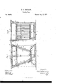
Be it known that I, EDWARD Y. CHEVALIER, of Fort Wayne, in the county of Allen and State of Indiana, have invented a new and Improved Bee-Hive; and Ido hereby declare that the followingv isafull, clear, and exact description of the same, reference beinghad to the accompanying drawings, making a part of this specitication, in whichv Figure 1 is a vertical central section of my invention, taken in the line m x, Fig. 2; Fig. 2,:a vertical section of the same, taken in the line y y, Fig. 1.
Similar letters of reference indicate corresponding parts in the two figures.
The invention consists in a novel and improved arrangement for catching the moth or miller, in connection with a Ventilating and feeding device, all arranged in such a manner that the ventilation of the hive may be regulated as desired, and the bees supplied with food without danger of being chilled in winter or exposed to drafts of cold air, and the moth or miller entrapped without difficulty and readily'removed when necessary.
To enable those skilled-in the art to fully understand and construct my invent-ion, I will proceed to describe it.
A represents the body of the hive, which is formed of two parallel sides, a a, having an inclined front and back piece, b, secured between them, the latter being shown clearly in Fig. 1. The front and back pieces, b b, do not extend down as low as the side pieces, a a, some distance being allowed between the lower ends of b b and a bottom plate or board, c, to which the sides a a are attached.
B represents a drawer which is tted in this space between the bottom board, c, and the lower end of the front and back pieces, b b, and is divided into three compartments, d d e, the latter being the central compartment and serving as a feed-receptacle, which, when the drawer is placed in proper position, is directly under the center of the hive, as shown in Fig. 1. rIhe feed-receptacle is provided with a lid, f, by which it may be cut oft' from the interior of the hive when desired. The upper ends of the compartments d d, immediately underneath the hive, are covered with wire-cloth g, while the ontersides ofsaid compartments are formed of slats h, the ends of which are secured by pivots or tenons in the sides of the drawer, in
order that they may be turned like the slats of a window-blind and form close sides, or be turned more or less open to admit of spaces -between them for the ingress of air and the moth or miller. The compartments d d there fore serve a double purpose-to wit, that of ventilators and moth-traps. The wire-cloth tops g admit of air passing up into the hive, but serve asbarriers to the moth or miller. In the front end piece I) of the hive, at its lower part, there is made a slot or opening, i, which serves as a bee-entrance, and directly over this entrance there is placed a metal slide, C, which is fitted between pins or guidesj. This slide works up and down over the entrance t', and by adjusting it the capacity of the former may be regulated, as desired. The slide C is se` cured at any desired point by a set-screw, lr, which passes through a vertical slot, Z, in the upper part of the slide O, and into the end piece Z. (Shown in Fig. 1.)
D represents t-he cap or top piece of the hive, which is removable, it being fitted on the top of the body A over cleats m, extending all around the upper edge of the latter. On the upper parts of the sides and ends a b of the body A there are secured blocks n, one at each angle or corner and one at the central parts of the side pieces, ct a, and on these blocks n the spare-honey boxes EE are placed, having a glass at one end in order that the interiors of the same may be inspected.
In the under side of the top D there are placed two screws, n n', which, when the top is adjusted on the hive and over the sparehoney boxes, rest or bear upon the latter and retain them in proper position, as shown in Fig. 1. The sides ot' the top D are provided with Ventilating-openings o, which may have covers p for the purpose of regulating their capacity, as may be required.
Within the body of the hive Athere are placed a series of comb-frames; F, the sides q of which are inclined corresponding to the inclination of the front and back ends, b b, of the hive, as shown in Fig. 1. The upper bars, r, of these frames are in a horizontal position, but the lower bars are slightly inclined, corresponding to the inclined position ofthe lid f of the feed box or receptacle e and the wirecloths g g, the inclination of said parts being downward from the back toward the front side of the hive, as shown in Fig. 1. A space is allowed between the comb-frames and the sides of the hive, and also between the tops of the comb-frames and the bottoms of the sparehoney boxes, the cleats n, on which the sparehoney boxes rest, forming the latter spaces, as will be seen by referring to Fig. 1. A space is also allowed all around the spare-honey boxes and the inner sides of the cap or top piece D, as shown in Fig. 1.
G represents tubes which are inserted in the comb-frames F when the latter are filled. These tubes are short and are not designed to be longer than the thickness of the combs in the frames, and they afford passages for the bees through the combs, enabling the former to pass from one side of the hive to the other without passing around at the outer sides of the comb frames. By this arrangement the bees are -prevented from being chilled in winter or cool weather, and the combs, in not being'traveled over so much as they otherwise would be, are kept comparatively clean and fresh.
By having the spaces extend all around the hive between its inner sides and the combframes, and also between the inner sides of the cap or top piece and the spare-honey boxes, and having the moth traps or compartments d d in the drawer B provided with the adjust able slats h at their ends, and their tops provided with wire-cloth covers g, the hive may 'be perfectly ventilated at all times, more or less air admitted as the temperature of the atmosphere will admit, and by simply removing or taking out the drawer B the feed-receptacle e may be replenished when necessary and the moths or millers removed from the compartments d d, the wire-cloths g being placed in hinged covers in order to afford easyA access to the compartments d d.
The advantages of feeding the bees, proper ventilation of the hive, and the varying of the capacity of the bee-entrance, as well as the keeping the bees in a compact state in winter, being well known to all apiarists, do not require to be fully set forth. There is, however. an advantage attending the placing of thesparehoney boxes E on the blocks n, which should be mentioned-and that is, the bees are prevented from gluing the boxes downto the hive, a result which renders their removal rather troublesome and causes the hives to be shaken or jarred and the bees annoyed thereby.
Having thus described my invention, what I claim as new, and desire to secure by Letters Patent, is-
The drawer B, provided with the feed-receptacle e and the ventilating-compartments and moth-traps d d, the latter being provided with adjustable slats h and wire-cloths g g, and all arranged, relatively with the hive, to operate as and for the purpose set forth.
EDWARD Y. CHEVALlER.
Witnesses:
JAMES PLOWMAN, RICHARD G. WADGE.
Publications (1)
| Publication Number | Publication Date |
|---|---|
| US36070A true US36070A (en) | 1862-08-05 |
Family
ID=2105647
Family Applications (1)
| Application Number | Title | Priority Date | Filing Date |
|---|---|---|---|
| US36070D Expired - Lifetime US36070A (en) | Improvement in bee-hives |
Country Status (1)
| Country | Link |
|---|---|
| US (1) | US36070A (en) |
Cited By (3)
| Publication number | Priority date | Publication date | Assignee | Title |
|---|---|---|---|---|
| US20030183351A1 (en) * | 1999-02-24 | 2003-10-02 | Sealey James E. | Use of thinnings and other low specific gravity wood for lyocell pulps method |
| US20040207110A1 (en) * | 2003-04-16 | 2004-10-21 | Mengkui Luo | Shaped article from unbleached pulp and the process |
| US20100288456A1 (en) * | 2009-05-14 | 2010-11-18 | Weyerhaeuser Nr Company | Fibrillated blend of lyocell low dp pulp |
-
0
- US US36070D patent/US36070A/en not_active Expired - Lifetime
Cited By (3)
| Publication number | Priority date | Publication date | Assignee | Title |
|---|---|---|---|---|
| US20030183351A1 (en) * | 1999-02-24 | 2003-10-02 | Sealey James E. | Use of thinnings and other low specific gravity wood for lyocell pulps method |
| US20040207110A1 (en) * | 2003-04-16 | 2004-10-21 | Mengkui Luo | Shaped article from unbleached pulp and the process |
| US20100288456A1 (en) * | 2009-05-14 | 2010-11-18 | Weyerhaeuser Nr Company | Fibrillated blend of lyocell low dp pulp |
Similar Documents
| Publication | Publication Date | Title |
|---|---|---|
| US36070A (en) | Improvement in bee-hives | |
| US32101A (en) | Beehive | |
| US33499A (en) | Improvement in bee-hives | |
| US29848A (en) | williams | |
| US37310A (en) | Improvement in bee-hives | |
| US32367A (en) | Beehive | |
| US129464A (en) | Improvement in bee-hives | |
| US35426A (en) | Improvement in bee-hives | |
| US50179A (en) | Improvement in bee-hives | |
| US122279A (en) | Improvement in bee-hives | |
| US33486A (en) | Improvement in bee-hives | |
| US175482A (en) | Improvement in bee-hives | |
| US84010A (en) | Improvement in bee-hives | |
| US144847A (en) | Improvement in bee-hives | |
| US39622A (en) | Improvement in bee-hives | |
| US86037A (en) | of monroe | |
| US41942A (en) | Improvement in bee-hives | |
| US22309A (en) | Beehive | |
| US40600A (en) | Improvement in bee-hives | |
| US183692A (en) | Improvement in bee-hives | |
| US290022A (en) | Alexandee fealey | |
| US302834A (en) | Bee-hive | |
| US38012A (en) | Improvement in bee-hives | |
| US51566A (en) | Improvement in bee-hives | |
| US86441A (en) | Improvement in bee-hives |