US3585337A - Forge welding by hi-frequency heating and metal deposition - Google Patents
Forge welding by hi-frequency heating and metal deposition Download PDFInfo
- Publication number
- US3585337A US3585337A US827530A US3585337DA US3585337A US 3585337 A US3585337 A US 3585337A US 827530 A US827530 A US 827530A US 3585337D A US3585337D A US 3585337DA US 3585337 A US3585337 A US 3585337A
- Authority
- US
- United States
- Prior art keywords
- edges
- weld
- molten metal
- workpieces
- weld point
- Prior art date
- Legal status (The legal status is an assumption and is not a legal conclusion. Google has not performed a legal analysis and makes no representation as to the accuracy of the status listed.)
- Expired - Lifetime
Links
- 238000010438 heat treatment Methods 0.000 title claims abstract description 61
- 238000003466 welding Methods 0.000 title claims abstract description 46
- 238000001465 metallisation Methods 0.000 title description 2
- 239000002184 metal Substances 0.000 claims abstract description 124
- 229910052751 metal Inorganic materials 0.000 claims abstract description 124
- 238000011144 upstream manufacturing Methods 0.000 claims description 10
- 239000000203 mixture Substances 0.000 claims description 7
- 238000000034 method Methods 0.000 claims description 6
- 238000005204 segregation Methods 0.000 claims description 6
- 230000015572 biosynthetic process Effects 0.000 claims description 2
- 238000003825 pressing Methods 0.000 claims description 2
- 230000006698 induction Effects 0.000 abstract description 12
- 238000005242 forging Methods 0.000 description 9
- XLYOFNOQVPJJNP-UHFFFAOYSA-N water Substances O XLYOFNOQVPJJNP-UHFFFAOYSA-N 0.000 description 7
- 150000002739 metals Chemical class 0.000 description 4
- 229910000831 Steel Inorganic materials 0.000 description 3
- 238000005520 cutting process Methods 0.000 description 3
- 239000000463 material Substances 0.000 description 3
- 239000010959 steel Substances 0.000 description 3
- 238000009826 distribution Methods 0.000 description 2
- 238000005304 joining Methods 0.000 description 2
- 101100180402 Caenorhabditis elegans jun-1 gene Proteins 0.000 description 1
- 238000005452 bending Methods 0.000 description 1
- 230000003247 decreasing effect Effects 0.000 description 1
- 239000012530 fluid Substances 0.000 description 1
- 230000017525 heat dissipation Effects 0.000 description 1
- 239000012535 impurity Substances 0.000 description 1
- 229910001338 liquidmetal Inorganic materials 0.000 description 1
- 238000012986 modification Methods 0.000 description 1
- 230000004048 modification Effects 0.000 description 1
- 238000007493 shaping process Methods 0.000 description 1
- 238000009827 uniform distribution Methods 0.000 description 1
Images

Classifications
-
- B—PERFORMING OPERATIONS; TRANSPORTING
- B23—MACHINE TOOLS; METAL-WORKING NOT OTHERWISE PROVIDED FOR
- B23K—SOLDERING OR UNSOLDERING; WELDING; CLADDING OR PLATING BY SOLDERING OR WELDING; CUTTING BY APPLYING HEAT LOCALLY, e.g. FLAME CUTTING; WORKING BY LASER BEAM
- B23K13/00—Welding by high-frequency current heating
- B23K13/01—Welding by high-frequency current heating by induction heating
- B23K13/02—Seam welding
- B23K13/025—Seam welding for tubes
Definitions
- a stream of hot molten metal droplets from a metallizing type of gun means is directed to and impinges upon the metal workpieces and amount of molten metal of the workpieces in the weld area.
- FIGQI VENTOR WALLACE C RUDD ATTORNEY PATENTED JUN1 sum 8,585,337
- the edges of the workpieces can be brought to forge welding temperature by high frequency resistance heating means or by high frequency induction heating means.
- a strip of metal When forming a tube, normally a strip of metal is shaped by forming rolls to urge the edges of the strip to converge to a weld point where they are forced together, generally by pressure rolls.
- the converging edges of the strip can be heated to welding temperature by an induction coil located around the tube a short distance in advance of the weld point, or by sliding contacts as disclosed in U.S. Pat. No. 2,818,488 entitled Tube Welding by W. C. Rudd et al. which heats the converging edges by high frequency resistance heating.
- the scarfing or cutting off of the weld upset from the bottom and top surfaces of the weld exposes the ends of the bent lines of segregation or planes of weakness and surface cracks called hook cracks sometimes result.
- a first heating means such as a high frequency resistance heating means or a high frequency induction heating means to initially heat the weld area to a desired temperature
- a metallizing gun arranged to feed a stream of molten droplets of metal to the initially heated weld area to increase the amount of molten metal in the weld area, less forging pressure is required to form a weld.
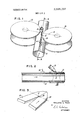
- FIG. 1 is a view, in perspective, of structure in accordance with the principles of this invention
- FIG. 2 is a view along the line 2-2 of FIG. 1;
- FIG. 3 is a view at the weld area, the metal forming rolls and metal heating means having been removed for purposes of clarity;
- FIG. 4 is a view looking into the weld area from a point upstream from the weld area
- FIG. 5 is a view in section of a typical weld seam
- FIG. 6 is a view of a weld seam in section illustrating the flow lines of metals brought to final heat with high frequency heating means and joined by forging;
- FIG. 7 is a view in section of a weld seam illustrating the improved flow lines of metals brought to a final melt condition in accordance with the principles of this invention.
- metal workpieces that are to be joined by welding are brought to a desired forge welding temperature by a first heating means such as high frequency resistance heating means, or high frequency induction heating means.
- a stream of hot molten metal droplets from a metallizing gun is directed to and impinges upon the metal workpieces to provide more plastic or fluid metal at the weld seam.
- the temperature of the workpieces may be increased. slightly by the stream of hot molten metal droplets from the metallizing gun.
- the rate of welding is high for relatively thick materials, approximately three-sixteenths of an inch or above, as the real heat contribution is' obtained from the high powered high frequency source; and the stream of hot molten metal droplets from the metallizing gun which is directed to impinge upon the surfaces to be joined at or just prior to the weld point provides additional melted or plastic metal than would normally be present across the interface by the use of the high frequency heating source separately.
- the high frequency heating means contributes the heat to the metals to be welded. However, it does not produce an optimuni uniformity of interface temperature and, as a result, heavy forging action is required to make a weld.
- the use of a metallizing gun type of means in combination with a high frequency heating means produces additional melted or plastic metal at the weld area, and substantially less forging pressure is required to make a weld. It is only by decreasing the forging pressure that the bending outward of the planes of weakness can be avoided and the tendency to produce hook cracks is reduced.
- FIG. 1 there is illustrated structure in accordance with the principles of this invention.
- a length of flat strip stock 10 is advanced through shaping rolls, the edges of the strip being positioned to come together to form a tube.
- the edges are welded together at a point 12.
- the edges of the strip can be heated to a desired temperature by an induction coil positioned around the tube, or by the use of high frequency resistance heating means utilizing two sliding contacts as disclosed in US. Pat. No. 2,818,488 entitled Tube Welding by W. C. Rudd et al.
- contacts l4, 16 for the high frequency current are appliedto the edges of the strip being shaped upstream from the weld point 12, and the high frequency current flows from one contact 14 along one edge of the strip to the weld point 12, then back along the other edge of the strip to the other contact 16 as illustrated by the dotted line 18.
- the current flowing through the edges of the strip 10 heats the edges of the strip to forge welding temperature.
- heating from the high frequency current ceases a small distance upstream from the intersection of the line 20 which extends through the centers of the squeeze rolls 22 and 24 with the weld seam being formed in the tube.
- FIGS. 1 and 3 through of U.S. Pat. No. 2,818,488 can be used, it being understood that the figures and description of US. Pat. No. 2,818,488 is made a part of this description the same as if it had been actually incorporated herein.
- a stream of hot molten metal droplets from a metallizing gun-type of means 26 is positioned to impinge upon the heated edges of the strip at or slightly upstream from the point 12.
- the additional molten or plastic metal applied to the facing metal edges of the tube by the stream from the metallizing gun-type of means helps to improve the temperature distribution of the hot edges at the point 12 in addition to providing and adding additional melted or plastic metal for producing the improved type of weld.
- FIG. 2 there is illustrated a view along the line 2-2 of FIG. 1 showing the contact 14 riding on the top surface of the strip 10, a squeeze roll, and the metallizing gun type of means 26 positioned to direct a stream of hot molten metal droplets to impinge upon the edges to be welded at the weld point 12.
- the stream of hot molten metal droplets follows a path that is at an angle with the weld seam being formed, in some instances it may be desirable to have the stream of hot molten metal droplets follow a path that is perpendicular or at right angles to the seam being formed and the longitudinal axis of the tube.
- FIG. 3 is a view of the metal strip 10 at the weld area, the metal forming rolls and metal heating means having been removed for purposes of clarity.
- the edges of the strips are brought together. It is at this junction that the high frequency heating current crosses from one edge to the other edge. It is also at this junction that forging action normally occurs to create the upset that causes the undesired hook cracks.
- the area identified by reference numeral 28 which can surround the weld point 12 defines the target area for the hot stream of molten metal droplets; the target area including the apex of the V from the top surface of the strip 10 through to the bottom surface of the strip 10.
- FIG. 4 is a view looking into the weld area upstream from the weld point 12. It is to be noted that while the contacts are not shown, when high frequency resistance heating is used the heating current flows along the sides of the two edges and the stream of hot molten metal'droplets impinges on the sides of the two edges. In some instances a small portion of the stream of hot molten metal droplets 'may pass through the V gap, and, in those instances where .a tube is being formed, will pass through and deposit metal on the opposite wall of the tube.
- a shield 30, which can be water-cooled, can be positioned within the tube to interrupt the stream of hot molten metal droplets.
- the shield 30 can have a concave shape to act as a channel for water, the water being either contained as in a trough or running.
- the small droplets of solidified metal will collect within the trough and, in time, will have to beemptied. In those instances where the water is running, the small droplets of solidified metal will be washed away by the moving water which can flow from the trough 30 to the inside of the pipe for eventual disposal.
- the trough 30 can be eliminated and the very bottom of the tube can act as the trough to carry water. In each instance, the water cools and solidifies the molten metal droplets in the hot stream before theycontact and adhere to the metal workpieces.
- FIG. 5 illustrates, in section, a typical weld seam obtained when using the structure of this invention.
- the high frequency heating means is the main source of heat, and the stream of hot molten metaldroplets supplies additional molten metal. The result is a pinched centerheat affected area 32. The absence of the large upset is to be noted'as less forge pressure is required to make the weld.
- FIG. 6 is a view of a weld scam in section illustrating the flow lines of metal brought to final heat with high frequency resistance heating means or high frequency induction heating means only. it should be noted how the flow lines bend outward. Removal of the upset results in the cutting of the flow lines.
- FIG. 7 there is illustrated a view in section of a weld seam brought to a desired temperature by high frequency resistance heating means or high frequency induction heating means and to a final melt state by a stream of hot molten metal droplets from a metallizing type of gun means. It is to be noted .that the flow lines are positioned end to end and are not reoriented at right angles to their normal positions as shown in FIG. 6.
- the main source of welding power that raises the temperature of the workpieces to a desired temperature can be a high frequency resistance heating means, high frequency induction heating means where the coil is positioned around the workpiece such as a tube or the like, or a high frequency induction heating means where the induction coil is operated in the 3,000 to 10,000 cycles per second range, the coil being positioned over the tube rather than around it.
- the metallizing type of gun means can be positioned to direct the stream of hot molten metal droplets either straight down onto the two workpieces or at a desired angle to the workpieces.
- the stream of hot molten metal droplets should be positioned to impinge upon the metal workpieces completely across the workpiece faces that are to be welded.
- the high frequency heating means contributes the heat required to forge weld the two edges together.
- the high-frequency heating means does not produce a temperature at the apex of the V that is as uniform as desired and, without the additional melt that is supplied by the stream of hot molten metal droplets, heavy forging action wouldbe required to make a weld.
- the stream of hot molten metal droplets in combination with the high frequency heating means provides more uniform temperature distribution across the faces that are to be welded at the apex of the V, and much less forging pressure is required to make the weld.
- the additional metal obtained from the stream of hot molten metal droplets forms an additional amount of melt on the faces that are to be welded.
- the rate of welding relatively thick materials is high when using high frequency heating means in combination with a stream of hot molten metal droplets as the high frequency heating means supplies the heat required and the stream of hot molten metal droplets provides the additional melt to the faces at the apex of the V.
- the metal or the composition of the metal in the stream of hot molten metal droplets can be similar to or different from the metal or the composition of the metal of the workpieces. In those instances where dissimilar metals are being welded together, the metal or the composition of the metal in the stream of hot molten metal droplets can be similar to one or not similar to either of the workpieces. In either event, the metal in the stream of hot molten metal should be such that it wets each of the surfaces of the workpieces that are being joined together by welding.
- Method for welding a seam extending along opposed edges of two elongated metal portions which comprises: rapidly advancing said portions with their said edges passing along the line of the desired seam and past a weld point; firmly retaining said edges together as they reach the region of said weld point; maintaining on said edges over a distance substantially in advance of said weld point, flows of electrical current of a frequency of the order of 10,000 cycles per second or higher for progressively heating such edges up to welding temperature upon reaching said point; and directing a stream of hot molten metal droplets upon the edges at or immediately upstream of the weld point to add hot metal to said edges.
- Apparatus for welding together two edges to' form a weld seam comprising means for advancing said edges in spaced apart relationship and for bringing the edges together at a desired weld point thereby toform a V-shaped configuration of said edges in advance of said weld point, means for applying a high frequency heating current which flows in a path along one edge to said weld point and then along the other edge to heat said edge substantially to welding temperature, means disposed outside of said V-shaped configuration. and away from said current path for directing a stream of molten metal droplets onto said edges at or immediately in advance of said weld point, means for applying welding pressure to said edges substantially at said weld point to form said weld seam.
- Method for welding together the edges of a longitudinal gap in metal tubing which comprises longitudinally advancing the tubing while subjecting the same to pressure from opposite sides thereof to bring the gap edges together at a welding point as a narrow V-shaped formation, and while heating said edges to forge welding temperature by applying high frequency current thereto, directing from a position transverse to said tubing a stream of hot molten metal droplets upon the gap edges at or immediately upstream of the weld point for adding hot molten to the edges at the weld point.
Landscapes
- Engineering & Computer Science (AREA)
- Mechanical Engineering (AREA)
- Pressure Welding/Diffusion-Bonding (AREA)
Abstract
Metal workpieces that are to be joined by welding are brought to or near forge welding temperature by a first heating means such as a high frequency resistance heating means or a high frequency induction heating means. At the same time that the workpieces are being heated to their desired temperature by the first heating means or at a short interval of time thereafter, a stream of hot molten metal droplets from a metallizing type of gun means is directed to and impinges upon the metal workpieces and amount of molten metal of the workpieces in the weld area.
Description
United States Patent Wallace C. Rudd Larchmont, N.Y. 827,530
May 26, 1969 June 15, 1971 AME incorporated [72] Inventor [2 1] Appl. No. [22] Filed [45] Patented [73] Assignee [54] FORGE WELDING BY Hl-FREQUENCY HEATING AND METAL DEPOSITION 9 Claims, 7 Drawing Figs.
[52] [1.8. CI 219/67, 219/59, 219/64, 219/101, 219/104 [51] lnt.Cl 823k 31/06 [50] Field of Search 219/59, 62, 64, 67,101-107, 8.5, l17;29/477.7, 503
[56] References Cited UNITED STATES PATENTS 2,818,488 12/1951 Ruddetal.
2,931,885 4/1960 Underwood et al. 219/67 3,028,469 4/1962 Bognar 2l9/8.5 3,288,982 11/1966 Suzuki etal. 219/137 3,385,948 5/1968 Redmond Primary Examiner-J. V. Truhe Assistant Examiner-L. A. Schutzman Attorneys-George W. Price and Eli Weiss ABSTRACT: Metal workpieces that are to be joined by welding are brought to or near forge we'lding'temperature by a first heating means such as a high frequency resistance heating means or a high frequency induction heating means. At the same time that the workpieces are being heated to their desired temperature by the first heating means or at a short interval of time thereafter, a stream of hot molten metal droplets from a metallizing type of gun means is directed to and impinges upon the metal workpieces and amount of molten metal of the workpieces in the weld area.
PATENTED JUNI 5 ISYI 585.337
' sum 1 or 2 FIGQI VENTOR WALLACE C. RUDD ATTORNEY PATENTED JUN1 sum 8,585,337
INVENTOR WALLACE C. RUDD ATTORNEY FORGE WELDING BY III- FREQUENCY HEATING AND METAL DEPOSITION- This invention relates generally'to methods and apparatus adapted for joining by welding two metal workpieces and more particularly to the forge welding of longitudinal seams in a shaped metal strip to form a metal tube, where droplets of molten metal such as is obtained from a metallizing gun are directed to fall upon the weld area to increase the amount of molten metal in the weld area subsequent to the weld area having been initially heated to a desired temperature.
In one method of joining by welding two metal workpieces, the edges of the workpieces can be brought to forge welding temperature by high frequency resistance heating means or by high frequency induction heating means.
When forming a tube, normally a strip of metal is shaped by forming rolls to urge the edges of the strip to converge to a weld point where they are forced together, generally by pressure rolls. The converging edges of the strip can be heated to welding temperature by an induction coil located around the tube a short distance in advance of the weld point, or by sliding contacts as disclosed in U.S. Pat. No. 2,818,488 entitled Tube Welding by W. C. Rudd et al. which heats the converging edges by high frequency resistance heating.
However, certain types of steels contain lines of segregation or planes of weakness. When the edges of such steels are forced together as occurs when making tubes or structural members, particularly when the steel has a dimension of approximately three-sixteenths of an inch or above, the forcing together of the edges during the forging action causes the segregated lines to be bent outward and at right angles to their original plane.
The scarfing or cutting off of the weld upset from the bottom and top surfaces of the weld exposes the ends of the bent lines of segregation or planes of weakness and surface cracks called hook cracks sometimes result.
By using, in combination, a first heating means such as a high frequency resistance heating means or a high frequency induction heating means to initially heat the weld area to a desired temperature together with a metallizing gun arranged to feed a stream of molten droplets of metal to the initially heated weld area to increase the amount of molten metal in the weld area, less forging pressure is required to form a weld.
It is an object of this invention to use a metallizing gun to bring the edges of workpieces which are to be welded together to a condition more suitable for forge welding.
It is an additional object of this invention to increase the amount of molten'metal in the weld zone of workpieces which are being welded together.
It is another object of this invention to add metal to the weld zone of workpieces which are being welded together.
It is still another object of this invention to add molten metal to the weld zone of workpieces which are being welded together where the metal added comes from a metallizing gun and is similar to that of one or both of the workpieces.
It is still another object of this invention to add molten metal to the weld zone of workpieces which are being welded together where the metal added comes from a metallizing gun and is not similar to that of one or both of the workpieces.
It is still another object of this invention to add molten metal to the weld zone of workpieces which are being welded together to provide a weld having improved characteristics.
It is another object of this invention to provide an improved weld of two workpieces brought to a final plastic state by a stream of hot molten metal droplets from a metallizing gun.
It is still another object of this invention to increase the rate of welding of two workpieces brought to a final plastic state by a stream of hot molten metal droplets from a metallizing gun.
It is yet another object of this invention to provide sufficient liquid metal so that oxides, inclusions, and extraneous material can be squeezed out to provide an improved weld of two workpieces brought to welding conditions by a stream of hot molten metal droplets from a metallizing gun. Other objects and many of the attendant advantages of this invention will be readily appreciated as the same become better understood by reference to the following detailed description when considered in connection with the accompanying drawings wherein:
FIG. 1 is a view, in perspective, of structure in accordance with the principles of this invention;
FIG. 2 is a view along the line 2-2 of FIG. 1;
FIG. 3 is a view at the weld area, the metal forming rolls and metal heating means having been removed for purposes of clarity;
FIG. 4 is a view looking into the weld area from a point upstream from the weld area;
FIG. 5 is a view in section of a typical weld seam;
FIG. 6 is a view of a weld seam in section illustrating the flow lines of metals brought to final heat with high frequency heating means and joined by forging; and
FIG. 7 is a view in section of a weld seam illustrating the improved flow lines of metals brought to a final melt condition in accordance with the principles of this invention. In this invention, metal workpieces that are to be joined by welding are brought to a desired forge welding temperature by a first heating means such as high frequency resistance heating means, or high frequency induction heating means. At the same time that the workpieces are being heated to their desired temperature by the heating means or at a short interval of time thereafter, a stream of hot molten metal droplets from a metallizing gun is directed to and impinges upon the metal workpieces to provide more plastic or fluid metal at the weld seam. In those instances where the rate of heat supplied to the workpieces by the stream of hot molten metal droplets from a metallizing gun is greater than the rate of heat dissipation of the workpiece, then the temperature of the workpieces may be increased. slightly by the stream of hot molten metal droplets from the metallizing gun.
The rate of welding is high for relatively thick materials, approximately three-sixteenths of an inch or above, as the real heat contribution is' obtained from the high powered high frequency source; and the stream of hot molten metal droplets from the metallizing gun which is directed to impinge upon the surfaces to be joined at or just prior to the weld point provides additional melted or plastic metal than would normally be present across the interface by the use of the high frequency heating source separately.
The high frequency heating means contributes the heat to the metals to be welded. However, it does not produce an optimuni uniformity of interface temperature and, as a result, heavy forging action is required to make a weld. The use of a metallizing gun type of means in combination with a high frequency heating means produces additional melted or plastic metal at the weld area, and substantially less forging pressure is required to make a weld. It is only by decreasing the forging pressure that the bending outward of the planes of weakness can be avoided and the tendency to produce hook cracks is reduced.
Thus, the stream of hot molten metal droplets from a metallizing gun produces a final molten face on the heated edges that are to be welded either where they come together or just upstream of the weld point. The molten metal together with surface impurities is squeezed out by the squeeze or forge rolls, substantially less pressure being required to form the weld than if the high frequency heating means were used without the stream of hot molten metal droplets from a metallizing type of gun.
Referring to FIG. 1 there is illustrated structure in accordance with the principles of this invention. A length of flat strip stock 10 is advanced through shaping rolls, the edges of the strip being positioned to come together to form a tube. The edges are welded together at a point 12.
Before reaching the weld point 12, the edges of the strip can be heated to a desired temperature by an induction coil positioned around the tube, or by the use of high frequency resistance heating means utilizing two sliding contacts as disclosed in US. Pat. No. 2,818,488 entitled Tube Welding by W. C. Rudd et al.
In those instances where high frequency resistance heating is utilized, contacts l4, 16 for the high frequency current are appliedto the edges of the strip being shaped upstream from the weld point 12, and the high frequency current flows from one contact 14 along one edge of the strip to the weld point 12, then back along the other edge of the strip to the other contact 16 as illustrated by the dotted line 18. The current flowing through the edges of the strip 10 heats the edges of the strip to forge welding temperature. Actually, heating from the high frequency current ceases a small distance upstream from the intersection of the line 20 which extends through the centers of the squeeze rolls 22 and 24 with the weld seam being formed in the tube.
In those instances where high frequency resistance heating is utilized, the structure'as disclosed in FIGS. 1 and 3 through of U.S. Pat. No. 2,818,488 can be used, it being understood that the figures and description of US. Pat. No. 2,818,488 is made a part of this description the same as if it had been actually incorporated herein.
A stream of hot molten metal droplets from a metallizing gun-type of means 26 is positioned to impinge upon the heated edges of the strip at or slightly upstream from the point 12.
The additional molten or plastic metal applied to the facing metal edges of the tube by the stream from the metallizing gun-type of means helps to improve the temperature distribution of the hot edges at the point 12 in addition to providing and adding additional melted or plastic metal for producing the improved type of weld.
Referring now to FIG. 2, there is illustrated a view along the line 2-2 of FIG. 1 showing the contact 14 riding on the top surface of the strip 10, a squeeze roll, and the metallizing gun type of means 26 positioned to direct a stream of hot molten metal droplets to impinge upon the edges to be welded at the weld point 12. it is to be noted that while the stream of hot molten metal droplets follows a path that is at an angle with the weld seam being formed, in some instances it may be desirable to have the stream of hot molten metal droplets follow a path that is perpendicular or at right angles to the seam being formed and the longitudinal axis of the tube.
FIG. 3 is a view of the metal strip 10 at the weld area, the metal forming rolls and metal heating means having been removed for purposes of clarity. At the apex of the V, the edges of the strips are brought together. It is at this junction that the high frequency heating current crosses from one edge to the other edge. It is also at this junction that forging action normally occurs to create the upset that causes the undesired hook cracks. The area identified by reference numeral 28 which can surround the weld point 12 defines the target area for the hot stream of molten metal droplets; the target area including the apex of the V from the top surface of the strip 10 through to the bottom surface of the strip 10.
FIG. 4 is a view looking into the weld area upstream from the weld point 12. It is to be noted that while the contacts are not shown, when high frequency resistance heating is used the heating current flows along the sides of the two edges and the stream of hot molten metal'droplets impinges on the sides of the two edges. In some instances a small portion of the stream of hot molten metal droplets 'may pass through the V gap, and, in those instances where .a tube is being formed, will pass through and deposit metal on the opposite wall of the tube. if the adding'of metal to the opposite wall of the tube is not desired by the stream of hot molten metal droplets, a shield 30, which can be water-cooled, can be positioned within the tube to interrupt the stream of hot molten metal droplets. If desired, the shield 30 can have a concave shape to act as a channel for water, the water being either contained as in a trough or running. When-the water is contained, the small droplets of solidified metal will collect within the trough and, in time, will have to beemptied. In those instances where the water is running, the small droplets of solidified metal will be washed away by the moving water which can flow from the trough 30 to the inside of the pipe for eventual disposal. If
desired, the trough 30 can be eliminated and the very bottom of the tube can act as the trough to carry water. In each instance, the water cools and solidifies the molten metal droplets in the hot stream before theycontact and adhere to the metal workpieces.
FIG. 5 illustrates, in section, a typical weld seam obtained when using the structure of this invention. .In this invention, the high frequency heating means is the main source of heat, and the stream of hot molten metaldroplets supplies additional molten metal. The result is a pinched centerheat affected area 32. The absence of the large upset is to be noted'as less forge pressure is required to make the weld. FIG. 6 is a view of a weld scam in section illustrating the flow lines of metal brought to final heat with high frequency resistance heating means or high frequency induction heating means only. it should be noted how the flow lines bend outward. Removal of the upset results in the cutting of the flow lines.
Referring to FIG. 7, there is illustrated a view in section of a weld seam brought to a desired temperature by high frequency resistance heating means or high frequency induction heating means and to a final melt state by a stream of hot molten metal droplets from a metallizing type of gun means. It is to be noted .that the flow lines are positioned end to end and are not reoriented at right angles to their normal positions as shown in FIG. 6.
The removal of the excess'metal 34 from the top and bottom surfaces of the weld does not result in the cutting of any of the flow lines.
In operation, in this invention, the main source of welding power that raises the temperature of the workpieces to a desired temperature can be a high frequency resistance heating means, high frequency induction heating means where the coil is positioned around the workpiece such as a tube or the like, or a high frequency induction heating means where the induction coil is operated in the 3,000 to 10,000 cycles per second range, the coil being positioned over the tube rather than around it.
The metallizing type of gun means can be positioned to direct the stream of hot molten metal droplets either straight down onto the two workpieces or at a desired angle to the workpieces. The stream of hot molten metal droplets should be positioned to impinge upon the metal workpieces completely across the workpiece faces that are to be welded.
The high frequency heating means contributes the heat required to forge weld the two edges together. However, by itself, the high-frequency heating means does not produce a temperature at the apex of the V that is as uniform as desired and, without the additional melt that is supplied by the stream of hot molten metal droplets, heavy forging action wouldbe required to make a weld. The stream of hot molten metal droplets in combination with the high frequency heating means provides more uniform temperature distribution across the faces that are to be welded at the apex of the V, and much less forging pressure is required to make the weld. The additional metal obtained from the stream of hot molten metal droplets forms an additional amount of melt on the faces that are to be welded.
Immediately downstream from the apex of the V, squeeze rolls force the two edges together to form a forge weld, the molten metal together with contained inclusions being squeezed out. In this invention, as there is additional melted metal present, in addition to a more uniform distribution of interface temperature, much less pressure is required to make the forge weld than would be required if high frequency heating without the stream of hot molten metal droplets were used.
Thus, the rate of welding relatively thick materials is high when using high frequency heating means in combination with a stream of hot molten metal droplets as the high frequency heating means supplies the heat required and the stream of hot molten metal droplets provides the additional melt to the faces at the apex of the V. Y
Depending upon the application for which the welded workpiece is to be used, the metal or the composition of the metal in the stream of hot molten metal droplets can be similar to or different from the metal or the composition of the metal of the workpieces. In those instances where dissimilar metals are being welded together, the metal or the composition of the metal in the stream of hot molten metal droplets can be similar to one or not similar to either of the workpieces. In either event, the metal in the stream of hot molten metal should be such that it wets each of the surfaces of the workpieces that are being joined together by welding.
Obviously many modifications and variations of the present invention are possible in the light of the above teachings. It is,
therefore, to be understood that within the scope of the appended claims the invention may be practiced otherwise than as specifically described herein.
I claim:
1. Method for welding a seam extending along opposed edges of two elongated metal portions, which comprises: rapidly advancing said portions with their said edges passing along the line of the desired seam and past a weld point; firmly retaining said edges together as they reach the region of said weld point; maintaining on said edges over a distance substantially in advance of said weld point, flows of electrical current of a frequency of the order of 10,000 cycles per second or higher for progressively heating such edges up to welding temperature upon reaching said point; and directing a stream of hot molten metal droplets upon the edges at or immediately upstream of the weld point to add hot metal to said edges.
2. Apparatus for welding together metal workpieces positioned prior to welding to form a V-shaped gap therebetween, the apex of the V being the weld point where the workpieces are joined to form a weld seam, comprising first heating means for heating the workpieces so that they are at a desired temperature at said weld point, a source of molten metal positioned at a location out of said V-shaped gap for directing a stream of molten metal droplets onto the workpieces at or slightly in advance of the weld point, thereby to add molten metal to said weld point, and means for forming said V-shaped gap between the workpieces.
3. The structure of claim 2 wherein the molten metal droplets of said stream of hot molten metal droplets has a composition similar to at least one of the edge surfaces of said workpieces.
4. The structure of claim 2 wherein the molten metal droplets of said stream of hot molten metal droplets has a composition dissimilar to the edge surfaces of said workpieces.
5. The apparatus of claim 2 wherein the source of molten metal is a metallizing gun which produces said stream of molten metal droplets.
6. The apparatus claimed in claim 5 wherein said first heating means heats the workpieces to forge welding temperature at said weld point, the apparatus further including means for applying pressure to said workpieces to produce a forge weld at the weld point but said pressure being insufficient to bend outwardly into the weld seam any lines of segregation present in the workpieces at the weld point.
7. Apparatus for welding together two edges to' form a weld seam, comprising means for advancing said edges in spaced apart relationship and for bringing the edges together at a desired weld point thereby toform a V-shaped configuration of said edges in advance of said weld point, means for applying a high frequency heating current which flows in a path along one edge to said weld point and then along the other edge to heat said edge substantially to welding temperature, means disposed outside of said V-shaped configuration. and away from said current path for directing a stream of molten metal droplets onto said edges at or immediately in advance of said weld point, means for applying welding pressure to said edges substantially at said weld point to form said weld seam.
8. The apparatus claimed in claim 7 wherein the means for applying welding pressure applies pressure sufficient to form a forge weld but insufficient pressure to bend outwardly into the weld seam any lines of segregation present at said edges as they reach the weld point.
9. Method for welding together the edges of a longitudinal gap in metal tubing which comprises longitudinally advancing the tubing while subjecting the same to pressure from opposite sides thereof to bring the gap edges together at a welding point as a narrow V-shaped formation, and while heating said edges to forge welding temperature by applying high frequency current thereto, directing from a position transverse to said tubing a stream of hot molten metal droplets upon the gap edges at or immediately upstream of the weld point for adding hot molten to the edges at the weld point.
Claims (9)
1. Method for welding a seam extending along opposed edges of two elongated metal portions, which comprises: rapidly advancing said portions with their said edges passing along the line of the desired seam and past a weld point; firmly retaining said edges together as they reach the region of said weld point; maintaining on said edges over a distance substantially in advance of said weld point, flows of electrical current of a frequency of the order of 10,000 cycles per second or higher for progressively heating such edges up to welding temperature upon reaching said point; and directing a stream of hot molten metal droplets upon the edges at or immediately upstream of the weld point to add hot metal to said edges.
2. Apparatus for welding together metal workpieces positioned prior to welding to form a V-shaped gap therebetween, the apex of the V being the weld point where the workpieces are joined to form a weld seam, comprising first heating means for heating the workpieces so that they are at a desired temperature at said weld point, a source of molten metal positioned at A location out of said V-shaped gap for directing a stream of molten metal droplets onto the workpieces at or slightly in advance of the weld point, thereby to add molten metal to said weld point, and means for forming said V-shaped gap between the workpieces.
3. The structure of claim 2 wherein the molten metal droplets of said stream of hot molten metal droplets has a composition similar to at least one of the edge surfaces of said workpieces.
4. The structure of claim 2 wherein the molten metal droplets of said stream of hot molten metal droplets has a composition dissimilar to the edge surfaces of said workpieces.
5. The apparatus of claim 2 wherein the source of molten metal is a metallizing gun which produces said stream of molten metal droplets.
6. The apparatus claimed in claim 5 wherein said first heating means heats the workpieces to forge welding temperature at said weld point, the apparatus further including means for applying pressure to said workpieces to produce a forge weld at the weld point but said pressure being insufficient to bend outwardly into the weld seam any lines of segregation present in the workpieces at the weld point.
7. Apparatus for welding together two edges to form a weld seam, comprising means for advancing said edges in spaced apart relationship and for bringing the edges together at a desired weld point thereby to form a V-shaped configuration of said edges in advance of said weld point, means for applying a high frequency heating current which flows in a path along one edge to said weld point and then along the other edge to heat said edge substantially to welding temperature, means disposed outside of said V-shaped configuration and away from said current path for directing a stream of molten metal droplets onto said edges at or immediately in advance of said weld point, means for applying welding pressure to said edges substantially at said weld point to form said weld seam.
8. The apparatus claimed in claim 7 wherein the means for applying welding pressure applies pressure sufficient to form a forge weld but insufficient pressure to bend outwardly into the weld seam any lines of segregation present at said edges as they reach the weld point.
9. Method for welding together the edges of a longitudinal gap in metal tubing which comprises longitudinally advancing the tubing while subjecting the same to pressure from opposite sides thereof to bring the gap edges together at a welding point as a narrow V-shaped formation, and while heating said edges to forge welding temperature by applying high frequency current thereto, directing from a position transverse to said tubing a stream of hot molten metal droplets upon the gap edges at or immediately upstream of the weld point for adding hot molten to the edges at the weld point.
Applications Claiming Priority (1)
| Application Number | Priority Date | Filing Date | Title |
|---|---|---|---|
| US82753069A | 1969-05-26 | 1969-05-26 |
Publications (1)
| Publication Number | Publication Date |
|---|---|
| US3585337A true US3585337A (en) | 1971-06-15 |
Family
ID=25249460
Family Applications (1)
| Application Number | Title | Priority Date | Filing Date |
|---|---|---|---|
| US827530A Expired - Lifetime US3585337A (en) | 1969-05-26 | 1969-05-26 | Forge welding by hi-frequency heating and metal deposition |
Country Status (1)
| Country | Link |
|---|---|
| US (1) | US3585337A (en) |
Cited By (7)
| Publication number | Priority date | Publication date | Assignee | Title |
|---|---|---|---|---|
| FR2209620A1 (en) * | 1972-12-11 | 1974-07-05 | Tenneco Inc | |
| US4242571A (en) * | 1979-01-29 | 1980-12-30 | Pauliukonis Richard S | Electro-thermal linear pull actuator |
| US5140123A (en) * | 1990-05-25 | 1992-08-18 | Kusakabe Electric & Machinery Co., Ltd. | Continuous manufacturing method for a metal welded tube and a manufacturing apparatus therefor |
| EP0739678A1 (en) * | 1995-04-28 | 1996-10-30 | Nkk Corporation | Method for producing an electric-resistance-welded steel pipe |
| US6288355B1 (en) * | 1996-04-22 | 2001-09-11 | Elpatronic Ag | Seam welding method and apparatus |
| USD459797S1 (en) | 2000-10-02 | 2002-07-02 | Fuji Electronics Industry Co., Ltd. | High-frequency heating coil for metal workpieces |
| FR2856465A1 (en) * | 2003-06-23 | 2004-12-24 | Commissariat Energie Atomique | HOLLOW ELEMENT CAPABLE OF BEING ASSEMBLED BY RELIANCE TO AN APPARENT ELEMENT |
Citations (5)
| Publication number | Priority date | Publication date | Assignee | Title |
|---|---|---|---|---|
| US2818488A (en) * | 1954-04-08 | 1957-12-31 | Magnetic Heating Corp | Tube welding |
| US2931885A (en) * | 1958-04-25 | 1960-04-05 | Armco Steel Corp | High frequency electric welding without rough and excessive inside flash |
| US3028469A (en) * | 1960-10-20 | 1962-04-03 | Yoder Co | High frequency welder assembly |
| US3288982A (en) * | 1964-03-14 | 1966-11-29 | Suzuki Haruyoshi | High speed arc welding method |
| US3385948A (en) * | 1965-01-13 | 1968-05-28 | Westinghouse Electric Corp | Seam welding method |
-
1969
- 1969-05-26 US US827530A patent/US3585337A/en not_active Expired - Lifetime
Patent Citations (5)
| Publication number | Priority date | Publication date | Assignee | Title |
|---|---|---|---|---|
| US2818488A (en) * | 1954-04-08 | 1957-12-31 | Magnetic Heating Corp | Tube welding |
| US2931885A (en) * | 1958-04-25 | 1960-04-05 | Armco Steel Corp | High frequency electric welding without rough and excessive inside flash |
| US3028469A (en) * | 1960-10-20 | 1962-04-03 | Yoder Co | High frequency welder assembly |
| US3288982A (en) * | 1964-03-14 | 1966-11-29 | Suzuki Haruyoshi | High speed arc welding method |
| US3385948A (en) * | 1965-01-13 | 1968-05-28 | Westinghouse Electric Corp | Seam welding method |
Cited By (10)
| Publication number | Priority date | Publication date | Assignee | Title |
|---|---|---|---|---|
| FR2209620A1 (en) * | 1972-12-11 | 1974-07-05 | Tenneco Inc | |
| US4242571A (en) * | 1979-01-29 | 1980-12-30 | Pauliukonis Richard S | Electro-thermal linear pull actuator |
| US5140123A (en) * | 1990-05-25 | 1992-08-18 | Kusakabe Electric & Machinery Co., Ltd. | Continuous manufacturing method for a metal welded tube and a manufacturing apparatus therefor |
| EP0739678A1 (en) * | 1995-04-28 | 1996-10-30 | Nkk Corporation | Method for producing an electric-resistance-welded steel pipe |
| US5900079A (en) * | 1995-04-28 | 1999-05-04 | Nkk Corporation | Method for producing a steel pipe using a high density energy beam |
| EP0933159A1 (en) * | 1995-04-28 | 1999-08-04 | Nkk Corporation | Method for producing a welded steel pipe |
| US6288355B1 (en) * | 1996-04-22 | 2001-09-11 | Elpatronic Ag | Seam welding method and apparatus |
| USD459797S1 (en) | 2000-10-02 | 2002-07-02 | Fuji Electronics Industry Co., Ltd. | High-frequency heating coil for metal workpieces |
| FR2856465A1 (en) * | 2003-06-23 | 2004-12-24 | Commissariat Energie Atomique | HOLLOW ELEMENT CAPABLE OF BEING ASSEMBLED BY RELIANCE TO AN APPARENT ELEMENT |
| EP1491807A1 (en) * | 2003-06-23 | 2004-12-29 | Commissariat A L'Energie Atomique | Pipe connection element |
Similar Documents
| Publication | Publication Date | Title |
|---|---|---|
| US3860778A (en) | Melt welding by high frequency electrical current | |
| US2315358A (en) | Electric metallic arc welding | |
| US3585337A (en) | Forge welding by hi-frequency heating and metal deposition | |
| US3588426A (en) | Method and apparatus for hi-frequency welding edges advanced in parallel | |
| US9676056B2 (en) | Method for joining two essentially metal sheet-type workpieces by means of friction squeeze welding using a filler material | |
| US4286744A (en) | Process for joining narrow width thin gage metal or alloy strip | |
| DE1440315B1 (en) | Process for the overlapping connection of the edge areas of metal sheets | |
| US2618845A (en) | Method of making tubes | |
| US2746141A (en) | Method of welding a tube | |
| US3541296A (en) | Welding of low thermal mass parts | |
| US3755884A (en) | Process for scarfing weld beads | |
| US3539761A (en) | Forge welding | |
| US3294928A (en) | Method and apparatus for seam welding of tubes | |
| US3131284A (en) | Non-consumable electrode arc welding of tubing | |
| JPH0418954B2 (en) | ||
| EP4164818B1 (en) | Seam guide assembly, welded tube roll forming apparatus with such seam guide asembly, and method of manufacturing a tube comprising aluminium or alloys thereof | |
| US3539760A (en) | Electron beam forge welding | |
| US4645893A (en) | Method for manufacturing spiral-welded steel pipe | |
| US3758740A (en) | Apparatus for scarfing weld beads | |
| US3944775A (en) | Welding process | |
| US3436521A (en) | Method of making composite panels by electric-arc braze-welding | |
| JPH0360883A (en) | Method for treating starting and finishing ends of laser beam welding | |
| US4376882A (en) | Method of resistance flash butt welding | |
| JP2017100173A (en) | Method for producing dissimilar metal conjugant | |
| JP2732935B2 (en) | Manufacturing method of powder filled tube |