US358317A - Telephone-exchange system - Google Patents
Telephone-exchange system Download PDFInfo
- Publication number
- US358317A US358317A US358317DA US358317A US 358317 A US358317 A US 358317A US 358317D A US358317D A US 358317DA US 358317 A US358317 A US 358317A
- Authority
- US
- United States
- Prior art keywords
- telephone
- sub
- station
- earth
- central station
- Prior art date
- Legal status (The legal status is an assumption and is not a legal conclusion. Google has not performed a legal analysis and makes no representation as to the accuracy of the status listed.)
- Expired - Lifetime
Links
- 230000011664 signaling Effects 0.000 description 10
- 239000004020 conductor Substances 0.000 description 8
- 230000000007 visual effect Effects 0.000 description 8
- 238000010276 construction Methods 0.000 description 6
- 230000004048 modification Effects 0.000 description 6
- 238000006011 modification reaction Methods 0.000 description 6
- 230000001020 rhythmical Effects 0.000 description 6
- 241000947840 Alteromonadales Species 0.000 description 2
- 230000004308 accommodation Effects 0.000 description 2
- 230000005540 biological transmission Effects 0.000 description 2
- 230000000875 corresponding Effects 0.000 description 2
- 230000000994 depressed Effects 0.000 description 2
- 230000000694 effects Effects 0.000 description 2
- 238000000034 method Methods 0.000 description 2
- 230000000284 resting Effects 0.000 description 2
Images

Classifications
-
- H—ELECTRICITY
- H04—ELECTRIC COMMUNICATION TECHNIQUE
- H04M—TELEPHONIC COMMUNICATION
- H04M9/00—Arrangements for interconnection not involving centralised switching
- H04M9/002—Arrangements for interconnection not involving centralised switching with subscriber controlled access to a line, i.e. key telephone systems
-
- H—ELECTRICITY
- H04—ELECTRIC COMMUNICATION TECHNIQUE
- H04Q—SELECTING
- H04Q2213/00—Indexing scheme relating to selecting arrangements in general and for multiplex systems
- H04Q2213/13096—Digital apparatus individually associated with a subscriber line, digital line circuits
Landscapes
- Engineering & Computer Science (AREA)
- Signal Processing (AREA)
- Structure Of Telephone Exchanges (AREA)
Description
, (No Model.) 2 Sheets-Sheet 1.
G. L. WILEY.
TELEPHONE EXCHANGE SYSTEM.
-810.858.817. 'P.tentea1=eb.22,1887.
(No Model.) l 2 sheets-sheen 2. v
G. L. WILEY.
, TELEPHONE EXCHANGE SYSTEM.
No. 358,317. Patented Feb. 22, 1887.1
AUNITED STATES PATENT OFFICE. 1
GEORGE L. WILEY, OF ELIZABETH, NEW JERSEY, ASSIGNOR TO THE WEST- ERN ELECTRIC MANUFACTURING COMPANY, OF CHICAGO, ILLINOIS.
TELEPHONE-EXCHANGE SYSTEM.
SPECIFICATION forming part oi" Letters Patent No. 358,317, dated February 22, 1887.
Application filed December 13, 1880. Serial No. 22,151.
.To all whom t may concern:
Be it known that LGEORGE L. WILEY, a citizen ofthe United States, and a resident of Elizabeth, in the county of Union and State of 5 New Jersey, have invented certain new and useful Improvements in Telephone-Exchange Systems and Circuits Therefor, of which the following is a specification.
My invention relates, especially, to that.
method of intercommunication which has received the name ofthe district or exchange telephone system,77 which consists of a central station connected by means of telegraph or telephone lines radiating in different direc` tions,with a number of sub-stations variously located within the geographical district'which the central station .is designed to serve. The organization and arrangement of the central station is such that any two of the sub-stations no may, at a moments notice, be placed in direct telegraphic or telephonie communication with each other by the act of a person who is in constant attendance at the central station, and who, upon being'notied to do so by either 2 5 party, connects together the two lines leading to the respective sub-stations, by means oi'suitable switching or connecting devices provided for this purpose.
Prior to the date of my invention it was 3o usual to place in connection with each substation line entering the central office an vlectro-magnetic alarm-bell or a visual indicator, termed an annunciatorj both of Well-known construction, so that when an electric current 3 5 was transmitted from one of the sub-stations to the central station a signal was given to the attendant, either by sounding the alarm-bell or by dropping the visual indicator, or both, whereupon the attendant would place his tele- 40 phone in connection with that line and ascertain what was wanted. Another method sometimes employed consisted in making use of a special signalingcircuit distinct from the substation lines and placing a person in constant attendance at a telephone connected with this circuit in the central station to receive the calls from the substations, and thus dispense with a separate signaling apparatus in connection Y with each line, as in the first-men 5o tioned arrangement.
(No model.)
The general object of my invention is to obviate certain objections incident to the meth ods heretofore in use, and at the same time to materially simplify both the construction and operation of a district or telephone-exchange system.
To this end my invention consists, first, in an improved combination of devices for operating district telephone or exchange systems, which consists of two or more lines ra- 6o diating from a central station to two or more sub-stations, a transmitting telephone connected with each of said lines at its sub-station, and a receiving-telephone at the central stat-ion included in an earth-wire which normally completes the circuit of all the sub-sta,- tion lines, by means of which the attendant at the central station may be at once informed what sub-station is desired to be connected without the necessity of preliminary signal- 7C ing; second, in the combination of two or more normally closed electric circuits extending from a central station to a like number of substations, a transmitting-telephone at each substation, and a receiving-telephone at the central station placed in an earthwire common to all the sub-station lines, whereby the attendant at the ieceivingtelephone in the central station may place himself within hearing of the transmittingteleplionesof all the sub-sta- 8o tions; third, in the combination ot' two or more normally-closed electric circuits, two or more transmitt-ing-telephones, and a receiving-telephone in an earth-wire common to all of said circuits, with an artificial resistance in said earth-wire and a condenser attached thereto, whereby rhythmical or telephonie vibrations may be readily conveyed to earth through the receivingtelephone, while ordinary electricalV l pulsations may be sent through or past thego central station without being materially affected by the action of the said earth-Wire; fourth, in the combination of two or more substation lines converging to a central station and united at that point to each other and to a single conductor, with a telephoneincluded in the circuit of the last-named conductor.
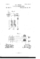
In the accompanying drawings, Figure 1 is a theoretical plan of' a central station and a. group of sub stations connected therewith roo which embodies my invention; and Figs. 2, 3, 4, and 5 are modifications of the same or of details of the same.
At the central station I provide a switchboard, S, for the purpose of facilitating-the connection and disconnection ot the different lines. This switch board may be of any of t-he well-known forms in general use for telegraphic purposes, although, for facility and convenience, I usually prefer to make use ol` the arrangement shown in the d rawings,which is knownas the lock-switch. This consists of a number of vertical metallic straps or bars, s s s, equal in number to the number of different substation lines for which accommodation is to be provided, which are arranged parallel to each other and close together, and are mounted upon a non-conducting frame or sup port. In front of these upright bars, and at right angles to them, is placedla second series of similar bars, s' s2, 83e., which are in like manner supported and insulated from each other, and are separated by a small interven ing space from the vertical bars ss s. At each crossing of one ot the longitudinal bars,in front ot' a vertical one, a hole is drilled transversely through both bars, so that aclosely-fitting metallic pin, as ppz, may be inserted, which, when in place, will form an electrical eonnection between the said bars.
The number of horizontal bars required in any particular case will usually be equal to about half the number of vertical bars, the number of the latter being determined bythe number of lines to be accommodated, as hereinbefore stated. The horizontal bars are connected in pairs to the terminals of a number of annnnciators or visual signals a a a, the construction and use of which will be hereinafter explained. One additional horizontal bar, g, is provided, which is connected with the earth at E by means of an earth-wire, e. In this earth-wire is placed a receiving telephone, T, and in connection with this I sometimes place a transmittingtelephone also, although this is not absolutely necessary in all eases.
The several line-wires designated by the numbers l 2 3 4, 83e., are connected with the corresponding vertical bars of the switch-board S, and extend thence to the respective sub stations, where they are severally connected with the earth. Two of these substations are shown at A and B in Fig. l, all the others being assumed to be precisely similar to these. Each sub-station is provided with avcall or alarm bell, r, a transmitting-telephone, T, a receiving-telephone, t, and a switch, q, (which may or may not be automatic in its action,) for placing either the telephone or the callbell in the circuit of the line, as desired. Il` preferred, the transmitting and receiving telephones may be combined in one and the same instrument.
\Vhen the apparatus thus described is at rest and in its normal position, switch-pegs p p2, Src., are inserted-in the lower bar, g, of the switch S, so as to electrically connect the series of vertical bars s s s, each with every other and with the earth, as shown in Fig. 1. The operation of effecting a special direct connection between any two sub-stations is then per` formed in the following manner: If a person, for example, at sub-station A wishes to communicate directly with the person at sub-Station B, he first speaks through the transmitting-telephone T to the attendant at the central station, who is continually listening at the telephone T, and informs him that he wishes to be connected with sub-station B. The attendant thereupon removes the pegs p and pz and places them in the holes h and l1?, the effeet of which is to disconnect the wires l and 2 from the receiving-telephoneT and from the earth, and to connect them directly with each other through thc bar s', annunciator a, and bar s2. Sub-station A fhen operates his signaling apparatus and rings the call-bell r, at substation B, and upon receiving his response proceeds to communicate with him inthe usual manner, precisely as if the two sub-stations were connected by a direct and wholly independent line. Vhen they have finished, one ofthem operateshissignaling apparatus, which drops the shutter of the annunciator a, thus notifying the attendant at the central station to restore the various connections to their nor mal position.
In lieu of the arrangement of annuneiators shown at a a in Fig. l, I often prefer, for the sake of simplicity, to make use of the ar `angement shown in Fig. 5, which consists of a receiving and transmitting telephone, l? and T", placed in an eartlrwire, c', which terminates in an extra vertical bar, g', upon the switchboard S. At some convenient point in the earth wire e',preferably between the telephone and the earth, I prefer to insert a rheostat or artificial resistance,lt,in connection with a condenser, C, one terminal of thelattcr being connected directly to the earth or tothe earth-wire below the rheostat,and the other terminal to the earth-wire between the rheostat and the switch board. In this case the attendant,after receiving a notification, as before, connects the wires l and 2, for example, upon the same horizontal bar, as s'. IIe can then at anytime, byin serting a connecting-peg at the intersection of the bars s' and Q',ascertain, bylistening at the telephone i?, whether the parties have completed their conversation, and this without interrupting their conversation or signaling,for the reason that while the rheostat lt prevents the escape to earth ot any considerable portion of signaling-currents passing between A and B, yet the condenser permits rhythmical vibrations or telephonie currents to pass with great facility, as is well understood by those skilled in the art. Y
Fig. 2 represents a modification of theswitchboard in which the earth-wire is connected to a detached section of each of the vertical bars, and thus a connection may be formed with any one of the bars by inserting between the bar and its detached section a divided peg, @which seam y s has the terminals of a telephone connected to its two insulated parts, as shown in the ligure.
Another modification is shown in Fig. 3, in which each horizontal connecting-bar of the switch-board has a sending and a receiving telephone normally connected between it and the earth through the resting contacts of keys lo and k2, which have their Working contactstops connected with a battery, F, common to all the bars. When a key is depressed,its telephone is thrown out of the circuit,and the current from the battery F is transmitted to the switch-board, and there divides and goes over both the sub-station lines connected with that horizontal bar,'so that the attendant at the central station may by this means simultaneously signal both substations,if desired. The rheostat and condenser, arranged as hereinbefore described,may be advantageously applied to this arrangement of circuits.
In Fig. 4 I have shown a modiiication in which the visual annunciator of Fig. l is replaced by an electro-magnetic bell and signaling-battery, H. This avoids the necessity of placing signaling-batteries or magneto-generators at the sub-stations, for the reason that the attendant at the central station having been, as heretofore explained, notified by telephone to make the desired, connection, does so, and at the same time includes the battery and alarm-bell in the connected circuit. The battery supplies a constant current through the coupled lines, by means of which one sub-station may signal the other in the ordinary manner by means of the battery located at the central station, and the two sub-stations may hold conversation with each other Without removing the battery from the circuit.
In constructing and arranging a telephoneexchange system in accordance with my invention it is in all cases desirable that the signaling electro magnet at each sub-station should be wound with a great number of convolutions of very line wire, so as to give a high resistance. This resistance will in all cases be removed from the circuit when the operator at the substation is using his telephone, and will therefore not interfere with the free transmission of communications, while the resistances remaining in circuit at each of the other sub-stations will oppose the tendency of the telephonie vibrations from the speaking-station to distribute themselves from the common earth-connection over all the other lines. The same effect may be produced, but less advantageously, by inserting special articial resistances in the several lines.
By the use of my invention it is possible to dispense with the cumbrous and expensive system heretofore employed of attaching an electro-magnetandannunciatororotherequivalent signal to each separate line entering the central station, and also to avoid the expense of the alternative method of constructing a separate circuit for signaling, while at the same time I am enabled to secure all the sub` stantial advantages of both these systems.
I make no claim to the combination and arrangement, which Ihave described and shown, of placing a visualv signal or annunciator in the circuit of two connected sub-station lines, for the purposeof notifying the attendant at the central station to restore the circuits to their normal condition after the two correspondents have finished their conversation.
I claim as my invention- 1. The combination, substantially as hereinbefore set forth, of two or more lines extending from a central station to two or more substations, a transmitting-telephone connected with each of said lines at its sub-station, and a receiving-telephone at the central station included in au earth-wire which normally completes the circuit of all the sub-station lines. 2. The combination, substantially as hereinbefore set forth, of two or more normallyclosed electric'ci'rcuits extending from a central station to two or more sub-stations, a transmitting-telephone at each sub-station, and a receiving-telephone at the central station in an earth-wire common to all the sub-station lines.
3. The combination, substantially as hereinbefore set forth, of two or more normallyclosed electric circuits extending from a central station to two or more sub-stations, a transmitting-telephone at each sub-station, a receiving-telephone at the central station in an earth-wire common to all the sub-station lines, an artificial resistance in said earth-wire, and a condenser attached to said earth-wire in such a manner as to transmit rhythmical Vibrations around said artificial resistance.
4. The combination, substantially as hereinbefore set forth, of two or more sub-station lines converging to a central station and united at that point to each other and t0 a single conductor and a telephone included in the circuit of the last-named conductor.
Signed by me this 9th day of December, A. D. 1880.
GEORGE L. WILEY.
"Witnesses:
NELSON ZABRIsKIE, MILLER O. EARLE.
Publications (1)
| Publication Number | Publication Date |
|---|---|
| US358317A true US358317A (en) | 1887-02-22 |
Family
ID=2427360
Family Applications (1)
| Application Number | Title | Priority Date | Filing Date |
|---|---|---|---|
| US358317D Expired - Lifetime US358317A (en) | Telephone-exchange system |
Country Status (1)
| Country | Link |
|---|---|
| US (1) | US358317A (en) |
-
0
- US US358317D patent/US358317A/en not_active Expired - Lifetime
Similar Documents
| Publication | Publication Date | Title |
|---|---|---|
| US358317A (en) | Telephone-exchange system | |
| US262261A (en) | vaillb | |
| US257664A (en) | Signments | |
| US266321A (en) | Chaelbs e | |
| US286595A (en) | Telephone-exchange system | |
| US684315A (en) | Multiple-switchboard system. | |
| US246481A (en) | Hobace h | |
| US248136A (en) | Assig-nob op two | |
| US513537A (en) | Charles e | |
| US339625A (en) | System of telephonic communication | |
| US491252A (en) | Metallic circuit for multiple-switch board systems | |
| US268294A (en) | James haeeis eogebs | |
| US299039A (en) | Electric multiple-switch-board system | |
| US382518A (en) | Telephone-exchange | |
| US319856A (en) | Telephone-exchange system and apparatus | |
| US252986A (en) | Telephone-exchange apparatus | |
| US518332A (en) | Telephone system | |
| US536382A (en) | Telephone-exchange system | |
| US328305A (en) | Leeoy beown fieman | |
| US544370A (en) | Automatic signaling device for telephone-switchboards | |
| US428189A (en) | Warner | |
| US245494A (en) | eewett | |
| US442144A (en) | sceibnee | |
| US220874A (en) | Improvement in telephone exchange systems and devices | |
| US632066A (en) | Telephone-exchange system. |