US3582575A - Composite conductor bar and method of manufacture - Google Patents
Composite conductor bar and method of manufacture Download PDFInfo
- Publication number
- US3582575A US3582575A US838558A US3582575DA US3582575A US 3582575 A US3582575 A US 3582575A US 838558 A US838558 A US 838558A US 3582575D A US3582575D A US 3582575DA US 3582575 A US3582575 A US 3582575A
- Authority
- US
- United States
- Prior art keywords
- bar
- cap
- conductor
- lock means
- leg
- Prior art date
- Legal status (The legal status is an assumption and is not a legal conclusion. Google has not performed a legal analysis and makes no representation as to the accuracy of the status listed.)
- Expired - Lifetime
Links
- 239000004020 conductor Substances 0.000 title claims abstract description 77
- 238000000034 method Methods 0.000 title claims description 18
- 239000002131 composite material Substances 0.000 title claims description 15
- 238000004519 manufacturing process Methods 0.000 title claims description 8
- 238000004080 punching Methods 0.000 claims abstract description 34
- 229910052782 aluminium Inorganic materials 0.000 claims abstract description 29
- XAGFODPZIPBFFR-UHFFFAOYSA-N aluminium Chemical compound [Al] XAGFODPZIPBFFR-UHFFFAOYSA-N 0.000 claims abstract description 29
- 239000000463 material Substances 0.000 claims abstract description 12
- 230000000452 restraining effect Effects 0.000 claims description 7
- 229910000838 Al alloy Inorganic materials 0.000 claims description 3
- 239000010935 stainless steel Substances 0.000 claims description 3
- 229910001220 stainless steel Inorganic materials 0.000 claims description 3
- 229910000831 Steel Inorganic materials 0.000 abstract description 25
- 239000010959 steel Substances 0.000 abstract description 25
- 235000010210 aluminium Nutrition 0.000 description 26
- 238000013459 approach Methods 0.000 description 5
- 230000008901 benefit Effects 0.000 description 4
- 229910052751 metal Inorganic materials 0.000 description 3
- 239000002184 metal Substances 0.000 description 3
- 238000005452 bending Methods 0.000 description 2
- 150000002739 metals Chemical class 0.000 description 2
- 238000003466 welding Methods 0.000 description 2
- 239000010963 304 stainless steel Substances 0.000 description 1
- 101100180402 Caenorhabditis elegans jun-1 gene Proteins 0.000 description 1
- 241000428199 Mustelinae Species 0.000 description 1
- 229910000589 SAE 304 stainless steel Inorganic materials 0.000 description 1
- 230000008602 contraction Effects 0.000 description 1
- 230000007423 decrease Effects 0.000 description 1
- 238000009826 distribution Methods 0.000 description 1
- 238000009434 installation Methods 0.000 description 1
- 230000003647 oxidation Effects 0.000 description 1
- 238000007254 oxidation reaction Methods 0.000 description 1
- TWNQGVIAIRXVLR-UHFFFAOYSA-N oxo(oxoalumanyloxy)alumane Chemical compound O=[Al]O[Al]=O TWNQGVIAIRXVLR-UHFFFAOYSA-N 0.000 description 1
- 230000035515 penetration Effects 0.000 description 1
Images


Classifications
-
- B—PERFORMING OPERATIONS; TRANSPORTING
- B21—MECHANICAL METAL-WORKING WITHOUT ESSENTIALLY REMOVING MATERIAL; PUNCHING METAL
- B21D—WORKING OR PROCESSING OF SHEET METAL OR METAL TUBES, RODS OR PROFILES WITHOUT ESSENTIALLY REMOVING MATERIAL; PUNCHING METAL
- B21D49/00—Sheathing or stiffening objects
-
- A—HUMAN NECESSITIES
- A63—SPORTS; GAMES; AMUSEMENTS
- A63H—TOYS, e.g. TOPS, DOLLS, HOOPS OR BUILDING BLOCKS
- A63H21/00—Other toy railways
- A63H21/04—Mono-railways, e.g. with vehicles embracing the rail in the form of a saddle
-
- B—PERFORMING OPERATIONS; TRANSPORTING
- B60—VEHICLES IN GENERAL
- B60M—POWER SUPPLY LINES, AND DEVICES ALONG RAILS, FOR ELECTRICALLY- PROPELLED VEHICLES
- B60M1/00—Power supply lines for contact with collector on vehicle
- B60M1/30—Power rails
- B60M1/302—Power rails composite
-
- Y—GENERAL TAGGING OF NEW TECHNOLOGICAL DEVELOPMENTS; GENERAL TAGGING OF CROSS-SECTIONAL TECHNOLOGIES SPANNING OVER SEVERAL SECTIONS OF THE IPC; TECHNICAL SUBJECTS COVERED BY FORMER USPC CROSS-REFERENCE ART COLLECTIONS [XRACs] AND DIGESTS
- Y10—TECHNICAL SUBJECTS COVERED BY FORMER USPC
- Y10T—TECHNICAL SUBJECTS COVERED BY FORMER US CLASSIFICATION
- Y10T29/00—Metal working
- Y10T29/49—Method of mechanical manufacture
- Y10T29/49002—Electrical device making
- Y10T29/49117—Conductor or circuit manufacturing
- Y10T29/49174—Assembling terminal to elongated conductor
-
- Y—GENERAL TAGGING OF NEW TECHNOLOGICAL DEVELOPMENTS; GENERAL TAGGING OF CROSS-SECTIONAL TECHNOLOGIES SPANNING OVER SEVERAL SECTIONS OF THE IPC; TECHNICAL SUBJECTS COVERED BY FORMER USPC CROSS-REFERENCE ART COLLECTIONS [XRACs] AND DIGESTS
- Y10—TECHNICAL SUBJECTS COVERED BY FORMER USPC
- Y10T—TECHNICAL SUBJECTS COVERED BY FORMER US CLASSIFICATION
- Y10T29/00—Metal working
- Y10T29/49—Method of mechanical manufacture
- Y10T29/49826—Assembling or joining
- Y10T29/49833—Punching, piercing or reaming part by surface of second part
-
- Y—GENERAL TAGGING OF NEW TECHNOLOGICAL DEVELOPMENTS; GENERAL TAGGING OF CROSS-SECTIONAL TECHNOLOGIES SPANNING OVER SEVERAL SECTIONS OF THE IPC; TECHNICAL SUBJECTS COVERED BY FORMER USPC CROSS-REFERENCE ART COLLECTIONS [XRACs] AND DIGESTS
- Y10—TECHNICAL SUBJECTS COVERED BY FORMER USPC
- Y10T—TECHNICAL SUBJECTS COVERED BY FORMER US CLASSIFICATION
- Y10T29/00—Metal working
- Y10T29/49—Method of mechanical manufacture
- Y10T29/49826—Assembling or joining
- Y10T29/49908—Joining by deforming
- Y10T29/49915—Overedge assembling of seated part
-
- Y—GENERAL TAGGING OF NEW TECHNOLOGICAL DEVELOPMENTS; GENERAL TAGGING OF CROSS-SECTIONAL TECHNOLOGIES SPANNING OVER SEVERAL SECTIONS OF THE IPC; TECHNICAL SUBJECTS COVERED BY FORMER USPC CROSS-REFERENCE ART COLLECTIONS [XRACs] AND DIGESTS
- Y10—TECHNICAL SUBJECTS COVERED BY FORMER USPC
- Y10T—TECHNICAL SUBJECTS COVERED BY FORMER US CLASSIFICATION
- Y10T29/00—Metal working
- Y10T29/49—Method of mechanical manufacture
- Y10T29/49826—Assembling or joining
- Y10T29/49908—Joining by deforming
- Y10T29/49925—Inward deformation of aperture or hollow body wall
-
- Y—GENERAL TAGGING OF NEW TECHNOLOGICAL DEVELOPMENTS; GENERAL TAGGING OF CROSS-SECTIONAL TECHNOLOGIES SPANNING OVER SEVERAL SECTIONS OF THE IPC; TECHNICAL SUBJECTS COVERED BY FORMER USPC CROSS-REFERENCE ART COLLECTIONS [XRACs] AND DIGESTS
- Y10—TECHNICAL SUBJECTS COVERED BY FORMER USPC
- Y10T—TECHNICAL SUBJECTS COVERED BY FORMER US CLASSIFICATION
- Y10T29/00—Metal working
- Y10T29/49—Method of mechanical manufacture
- Y10T29/49826—Assembling or joining
- Y10T29/49908—Joining by deforming
- Y10T29/49936—Surface interlocking
Definitions
- This invention relates to electrical distribution systems wherein a current collector slides in contact with an electrical conductor; and more particularly, relates to an improved com posite conductor for such a system and a method of manufacturing such a conductor.
- composite conductor bars have been employed wherein a steel cap is attached to the aluminum bar so that the steel forms the contacting surface for the current collector.
- Steel being much harder than aluminum, can, of course, withstand the constant wear of sliding contact much better than aluminum and also has a lower coefficient offriction.
- the composite conductor bar of the invention includes an elongated bar of good electrically conductive material, such as aluminum, with the bar having a front face and a pair of opposite sidewalls.
- a cap made of a conductive material such as stainless steel which is harder than the bar is forcefully pressed onto the conductor bar with its inner surface engaging the front and sidewalls of the bar.
- the cap is then securely attached to the bar by punching the side legs of the cap with a sharp punch or similar tool to form one or more tabs on the cap which are integral with the cap and have a portion which is cutaway from the cap material and embedded in the softer aluminum to lock the cap onto the bar.
- the tabs are formed in the steel cap on opposite legs of the cap at the same time so that the forces are balanced. This decreases the cost of the operation and also prevents bending of the bar out of the flat planes defined by the cap legs.
- the aluminum bar is positioned on one side supported on a spring loaded plate with the cap held under pressure against the face of the bar.
- An upper punch is driven against the upper leg of the cap forcing the bar and the spring loaded support plate downwardly against a lower punch aligned with the upper punch and extending through an opening in the plate.
- the punches are driven into the cap, simultaneously forming in a single operation tabs forced into the conductor bar.
- the lower support plate raises the bar away from the lower punch and by releasing the force clamping the cap onto the bar, the bar may be moved longitudinally to the position where an additional punching operation is to be performed.
- the cap is securely and permanently mechanically locked to the conductor bar, thus providing good electrical conductivity between the bar and the cap.
- the method of manufacture is relatively simple and inexpensive when compared to previous methods employed. The fact that basically only a single type of manufacturing step is utilized and this step may be performed by relatively unskilled operators, adds greatly to the low cost of the operation.
- FIG. 1 is a cross-sectional view of the apparatus employed in fabricating the composite bar of the invention, with a bar being shown in endwise cross section and the apparatus in position to perform a punching operation;
- FIG. 2 is a view similar to FIG. 1 with the apparatus shown performing a punching operation in accordance with the inventlon;
- FIG. 3 is an exploded perspective view of the die set apparatus used to employ the punching operation.
- FIGS. 47 are enlarged views of a portion of the bar and cap showing various forms of tabs punched into the cap and conductor bar.
- the composite conductor bar and cap is positioned with a die set generally indicated at 14 and including in its lower half a stripper plate 16 supporting the conductor bar.
- the stripper is supported by a plurality of coil springs 18 extending between the lower surface of the plate and the upper surface of a base member 20. Each spring surrounds a bolt 21 extending through the base member and threaded into the stripper plate 16.
- the stripper plate 16 is normally spaced from the base member 20 by the springs 18.
- a lower punch 22 having a sharp upper end is positioned in a holder 22a clamped to the base member 20 by means of a setscrew 24 extending through the front edge of the base member 20.
- the punch 22 extends upwardly through an aperture 23 in the stripper plate 16 and is vertically aligned with the lower leg 12a of the steel cap l2, as viewed in FIG. 1.
- the base member 20 is secured to a large supporting die plate 25.
- the upper half of the die set 14 includes an upper support member 26 which is comparable to the support member 20 and is attached to a hydraulic press 28.
- a clamp bar 30 is attached to the upper support member 26 by means of a plurality of bolts 32 extending through the support member 26 and threaded into the clamp bar 30.
- a plurality of springs 33 each surrounding one of the bolts 32 load the clamp bar 30 downwardly so that it is normally spaced from the support member 26 as shown in FIG. 1.
- An upper punch 34 positioned in a holder 34a which is clamped to the upper support member 26 by means of a suitable setscrew 36 extends downwardly through an opening 37 in the clamp bar 30.
- the punch 34 has a pointed lower end like the lower punch 22 and vertically aligned with the lower punch.
- a guide bar 40 Attached to the front of the stripper plate 16 by suitable bolts 38 is a guide bar 40. As seen from FIG. 1, the front face of the steel cap 12 engages the rear surface of the guide bar.
- a slide plate 42 is supported on the back side of the stripper plate 16 for slidable movement along the upper surface of the stripper plate as guided by the brackets 44 clamped to opposite sides of the rear of the stripper plate by suitable bolts 26.
- Lugs 48 attached to the rear edge of the stripper plate are connected by a pin 50 extending through a clevis 51 attached to the piston 52, which extends horizontally outwardly from a pneumatic ram cylinder 54.
- the upper halfofthe die set 14 is aligned with the lower half by a pair of guide pins 56 which are secured to the lower support member 20 and are slidably received in the upper support member 26.
- guide pins can be attached to the upper support member to slide into the lower member 20.
- the rear edge of the conductor bar 10 engages a restraining roller 57 horizontally mounted on a shaft 58 extending upwardly from the die plate 25.
- the roller is spring biased by the springs 59 so that it can move vertically with the bar 10.
- the remainder of the conductor bar which extends beyond the die set apparatus is supported by roller tables or other suitable means (not shown).
- the steel cap 12 is initially positioned on the conductor bar 10 by hand and positioned within the die set as shown in FIG. 1. Air pressure is then applied to the ram cylinder 54 driving the piston 52 forwardly, which in turn drives the slide plate 42 forwardly against the rear edge 10d of the conductor bar 10. The steel cap 12 is pressed against the guide bar 40 and hence the inner surface 12c of the cap forcefully engages the front face 10c of the conductor bar 10. In one successful example of this step of the operation, air pressure of approximately pounds per square inch is applied to the piston 52.
- the press 28 is actuated, moving the upper half of the die set downwardly.
- the clamp bar 30 contacts the upper leg 12b of the steel cap and pushes the bar and cap together with the stripper plate 16 downwardly until the cap lower leg 12a engages the sharpened upper end of the lower punch 22.
- Continued application of pressure forces the steel cap and the conductor bar onto the punch 22 until the lower surface of the stripper plate 16 engages the upper surface of the base member 20, as illustrated in FIG. 2 thus punching the lower punch 22 into the adjacent side leg of the steel cap and the side of the conductor bar.
- the clamp bar 30 is forced against the upper member 26 so that the upper punch 34 protrudes beyond the clamp bar 30 and punches into the upper leg 12b of the steel cap into the conductor bar, also as illustrated in FIG. 2. This action causes the sharpened punches to penetrate the steel cap and cut tabs integral with the cap which are punched into the conductor bar.
- the clamp bar 30 Upon raising the press 28, the clamp bar 30 is withdrawn and once more is urged away from the upper member 36 by its springs 33. Simultaneously, the stripper plate 16 is forced upwardly by its springs 18, raising the conductor bar 10 away from the lower punch 22. The air pressure on the ram 52 is reversed such that the stripper plate 42 is withdrawn, thus releasing the conductor. The bar is then drawn endwise to the succeeding punching position so that the punching step may be repeated.
- the number of operations necessary may vary with the dimensions of the materials employed; however, it has been found that punching locking tabs into the steel cap about every 6 inches along the longitudinal length of the bar provides a composite conductor with the cap tightly locked to the aluminum in good electrical contact. Simultaneously, punching the tabs on opposite sides of the bar balances the punching forces and prevents bending out of the planes defined by the legs of the cap.
- the cap will typically be made of 0302 or 304 stainless steel having a thickness of about one-sixteenth of an inch, or as thick as three thirty-seconds of an inch.
- the conductor bar could be made of extruded aluminum alloy 06063-T6.
- a pair of opposing tabs 64 are formed in the steel cap by utilizing a punch having a V-shape as viewed from the side, so that the sharp point is in the center of the punch. Thesetabs 64 tend to prevent movement of the cap in either direction relative to the conductor bar in view of the opposing edges 64a of the tabs. This tab is very effective when oriented in either the longitudinal direction of the conductor bar or perpendicular thereto.
- FIGS. 7a and 7b a pair of tabs 66 are formed extending downwardly from a central section 68 which is not displaced by the punch.
- the tool for forming these tabs had a pair of sharp edges on opposite edges with a V-shaped slot or groove between the edges when viewed from the side. Consequently, the forces again are balanced so that tool life .is enhanced.
- the tabs 66in FIGS. 7a and 7b tend to resist relative movement of the cap and bar although the. free ends 66a extend away from each other, while in FIGS. 6a and 6b, the freeends extend towards each other.
- one of said members including a pair of side legs for engaging side faces of the other member
- tab lock means formed integral with the side legs of the said one member including a portion cut away from each side leg and punched into the said other member for positively securing the cap member to the bar member, the tab lock means being the sole material embedded in the said other member for securing the cap member to the bar member.
- said tab lock means includes three tabs each having a generally triangular shape with one side of each of the triangular tabs being joined to the main body of said one member and the corner OPPOSIIG. said one side being the point of the cut away portion which is forced into said other member.
- an elongate bar made of aluminum alloy having a front face and opposite side faces;
- each tab lock means including a plurality of tabs symmetrically arranged in close proximity to each other, with each tab having an edge joined to the cap and. a tip portion cut away from the main body of the cap and punched into the bar a distance about equal to the thickness of the cap for positively locking the cap to the bar in good electrical and mechanical contact with the bar.
- a method of making a composite conductor comprising an electrically conductive bar and a cap having side legs-engaging the side faces of the bar and having an intermediate wall engaging the front face of the bar, the cap being made of electrically conductive material which is harder than the bar material so as to form a surface to be engaged by a slidable current collector, the steps comprising:
- the method of claim 9 including the steps of: positioning the bar on its side on a spring loaded plate hav ing one of the sharpened punches fixed to a base member beneath the plate with the sharpened tip of the punch extendingupwardly through an opening in the plate aligned with the lower leg of the cap;
- the method of claim 8 including the step of restraining the bar along its rear edge, which is remote from the cap so as to prevent the bar from curling as a result of the elongation to the bar occurring during-the punching operations.
Landscapes
- Engineering & Computer Science (AREA)
- Mechanical Engineering (AREA)
- Forging (AREA)
Abstract
An aluminum conductor bar is provided with a steel cap to form a wearing surface for a slidable current collector. The cap is secured to the bar by simultaneously punching the opposite side legs of the cap to form tabs integral with the cap material which extend into the aluminum to lock the cap securely onto the bar.
Description
United States Patent Inventor Appl.
Filed Patented Assignee Donald H. Scofield San Carlos, Calif. 838,558
July 2, 1969 June 1, 1971 Insul-S-Corp.
San Carlos, Calif.
COMPOSITE CONDUCTOR BAR AND METHOD OF MANUFACTURE 13 Claims, 11 Drawing Figs.
US. Cl l9l/29DM, 29/521, 29/624 Int. Cl. 860m 1/30 Field of Search 29/432,
624,521; 191/23 DM, 33 DM;23 8/143,l47, 148
283,760 2,084,322 2,254,558 Re25,6l5
References Cited UNITED STATES PATENTS 8/1883 Daft l9l/22(DM) 6/1937 Crane 238/148X 9/1941 Williams 29/432UX 7/1964 Reynolds et al. 29/521X FOREIGN PATENTS 0/1865 Great Britain 238/143 Prima'ry Examiner-Arthur L. LaPoint Assistant Examiner-George H. Libman Attorney-Fowler, Knobbe and Martens ABSTRACT: An aluminum conductor bar is provided with a steel cap to form a wearing surface for a slidable current collector. The cap is secured to the bar by simultaneously punching the opposite side legs of the cap to form tabs integral with the cap material which extend into the aluminum to lock the cap securely onto the bar.
I PATENTED JUN 1 l97l sum 1 or 4 INVENTOR. flOA/QLD H 570/7610 FOWL Z (A0555 .5 Mme-raw COMPOSITE CONDUCTOR IBAIR AND METHOD OF MANUFACTURE RELATED APPLICATIONS This application isrelated to application Ser. No. 771 ,931, filed Oct. 30, 1968 and assigned to the same assignee.
BACKGROUND OF THE INVENTION This invention relates to electrical distribution systems wherein a current collector slides in contact with an electrical conductor; and more particularly, relates to an improved com posite conductor for such a system and a method of manufacturing such a conductor.
Sliding contact electrification systems are used extensively in industry to provide electrical power to mobile apparatus such as cranes, monorails, overhead hoists, etc. Generally, such systems include a high amperage conductor extending along the path of the mobile apparatus, and a current collector mounted to move with the apparatus slidably engages an exposed face of the conductor to supply power to the apparatus.
In addition to low electrical resistance, a satisfactory conductor for such sliding contact systems must have a surface which makes a good electrical connection with the collector shoe and must be able to withstand the constant wear of the sliding collector shoe. Adequate structural strength is, of course, essential, and low cost is particularly significant in view of the large quantities of conductor bars required for many electrification systems.
Aluminum conductor bars have a relatively good combination of high structural strength, low electrical resistance, and low cost in comparison with conductor bars of other metals and are especially suitable for heavy duty installation wherein current requirements on the order of 500 or more amperes are needed. However, aluminum has severe disadvantages in a sliding contact system because aluminum oxide which forms on its surface is a very poor electrical conductor. Moreover, aluminum is a relatively soft metal and has a relatively high coefficient of friction. Hence, it affords a poor wearing surface for sliding contact.
To overcome these shortcomings of aluminum while still having the benefit of its many advantages, composite conductor bars have been employed wherein a steel cap is attached to the aluminum bar so that the steel forms the contacting surface for the current collector. Steel, being much harder than aluminum, can, of course, withstand the constant wear of sliding contact much better than aluminum and also has a lower coefficient offriction.
Various approaches have been utilized to secure the cap to the aluminum bar with a minimum of increased resistance being introduced by the steel cap. In one approach the holes are predrilled in the steel cap and aluminum plugs are then welded through the holes into the aluminum bar so that the welded plug securely attaches the cap to the bar. The welded aluminum plugs also make good electrical contact with the steel cap without having any undesirable oxidation of the alu minum. Consequently, most of the electrical transfer between the conductor bar and cap is through the aluminum welds. While this approach has met with considerable success, it is still naturally desirable that the cost for attaching the cap to the bar be reduced, in that the predrilling and the actual welding process requires skilled labor. Also, adding to the cost is the fact that the cap has to be carefully cleaned prior to the welding operation so as not to contaminate the welds. As a result of this, there is also some danger of bad welds occuring which may cause failure of the welded connection. Moreover, even with a good weld, there is some tendency for the weld to weaken after extended usage since most of the current flow is through the spot welds. Hence the cap may not remain securely attached to the conductor bar.
In other approaches steel caps have been bolted onto an aluminum bar, or nailed onto the bar by means of explosively driven nails. While these approaches have many advantages, they are still relatively expensive in view of the labor involved and the cost of the materials used in assembly. Hence, improvements in this regard are highly desirable.
SUMMARY OF THE INVENTION Briefly stated, the composite conductor bar of the invention includes an elongated bar of good electrically conductive material, such as aluminum, with the bar having a front face and a pair of opposite sidewalls. A cap made of a conductive material such as stainless steel which is harder than the bar is forcefully pressed onto the conductor bar with its inner surface engaging the front and sidewalls of the bar. The cap is then securely attached to the bar by punching the side legs of the cap with a sharp punch or similar tool to form one or more tabs on the cap which are integral with the cap and have a portion which is cutaway from the cap material and embedded in the softer aluminum to lock the cap onto the bar. Such tabs are employed at spaced intervals on both sides of the cap, and upon withdrawal of the punches form the sole material embedded in the bar to attach the cap to the bar. Preferably, the tabs on one side of the bar are aligned with those on the other side.
In accordance with the method of the invention, the tabs are formed in the steel cap on opposite legs of the cap at the same time so that the forces are balanced. This decreases the cost of the operation and also prevents bending of the bar out of the flat planes defined by the cap legs. Preferably, the aluminum bar is positioned on one side supported on a spring loaded plate with the cap held under pressure against the face of the bar. An upper punch is driven against the upper leg of the cap forcing the bar and the spring loaded support plate downwardly against a lower punch aligned with the upper punch and extending through an opening in the plate. By continued pressure through the upper punch, the punches are driven into the cap, simultaneously forming in a single operation tabs forced into the conductor bar. By withdrawing the upper punch, the lower support plate raises the bar away from the lower punch and by releasing the force clamping the cap onto the bar, the bar may be moved longitudinally to the position where an additional punching operation is to be performed.
Punching a series of tabs into the edge of a conductor bar deforms that edge of the bar slightly, causing it to elongate a slight amount. Over a long length of bar, this slight elongation can cause the bar to curl about an axis parallel to the punches used to form the tabs. To prevent this, the bar is restrained during the punching operation by positioning a restraining element downstream from the punching apparatus to engage the edge of the bar which is opposite from the steel cap.
With this method the cap is securely and permanently mechanically locked to the conductor bar, thus providing good electrical conductivity between the bar and the cap. The method of manufacture is relatively simple and inexpensive when compared to previous methods employed. The fact that basically only a single type of manufacturing step is utilized and this step may be performed by relatively unskilled operators, adds greatly to the low cost of the operation.
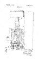
BRIEF DESCRIPTION OF THE DRAWINGS FIG. 1 is a cross-sectional view of the apparatus employed in fabricating the composite bar of the invention, with a bar being shown in endwise cross section and the apparatus in position to perform a punching operation;
FIG. 2 is a view similar to FIG. 1 with the apparatus shown performing a punching operation in accordance with the inventlon;
FIG. 3 is an exploded perspective view of the die set apparatus used to employ the punching operation; and
FIGS. 47 are enlarged views of a portion of the bar and cap showing various forms of tabs punched into the cap and conductor bar.
DETAILED DESCRIPTION OF PREFERRED EMBODIMENTS OF THE INVENTION Referring first to FIGS. 1 and 2, an aluminum conductor bar is shown positioned in endwise cross-sectional view supported on its lower side 10a and having an upper side 10b, a front face 100 and a rear edge 10d. The conductor bar 10 may extend longitudinally for a considerable distance, perhaps up to 30 ft. in length. A steel cap 12 is positioned on the front end of the bar with the cap having a lower side leg 12a engaging the lower side 10a of the conductor bar and an upper side leg 10b engaging the upper side 10b of the conductor bar while an intermediate wall 12c engages the front face 100 of the bar. The cap has a generally U-shaped cross section, but with a slight depression in its intermediate wall to conform to the shape of the bar such that the cap may be termed as having a W-shaped cross section.
The composite conductor bar and cap is positioned with a die set generally indicated at 14 and including in its lower half a stripper plate 16 supporting the conductor bar. As may be seen from FIGS. 1 and 3, the stripper is supported by a plurality of coil springs 18 extending between the lower surface of the plate and the upper surface of a base member 20. Each spring surrounds a bolt 21 extending through the base member and threaded into the stripper plate 16. As may be seen from FIG. 1, the stripper plate 16 is normally spaced from the base member 20 by the springs 18.
A lower punch 22 having a sharp upper end, is positioned in a holder 22a clamped to the base member 20 by means of a setscrew 24 extending through the front edge of the base member 20. The punch 22 extends upwardly through an aperture 23 in the stripper plate 16 and is vertically aligned with the lower leg 12a of the steel cap l2, as viewed in FIG. 1. The base member 20 is secured to a large supporting die plate 25.
The upper half of the die set 14 includes an upper support member 26 which is comparable to the support member 20 and is attached to a hydraulic press 28. A clamp bar 30 is attached to the upper support member 26 by means ofa plurality of bolts 32 extending through the support member 26 and threaded into the clamp bar 30. A plurality of springs 33 each surrounding one of the bolts 32 load the clamp bar 30 downwardly so that it is normally spaced from the support member 26 as shown in FIG. 1.
An upper punch 34 positioned in a holder 34a which is clamped to the upper support member 26 by means ofa suitable setscrew 36 extends downwardly through an opening 37 in the clamp bar 30. The punch 34 has a pointed lower end like the lower punch 22 and vertically aligned with the lower punch.
Attached to the front of the stripper plate 16 by suitable bolts 38 is a guide bar 40. As seen from FIG. 1, the front face of the steel cap 12 engages the rear surface of the guide bar. A slide plate 42 is supported on the back side of the stripper plate 16 for slidable movement along the upper surface of the stripper plate as guided by the brackets 44 clamped to opposite sides of the rear of the stripper plate by suitable bolts 26. Lugs 48 attached to the rear edge of the stripper plate are connected by a pin 50 extending through a clevis 51 attached to the piston 52, which extends horizontally outwardly from a pneumatic ram cylinder 54.
The upper halfofthe die set 14 is aligned with the lower half by a pair of guide pins 56 which are secured to the lower support member 20 and are slidably received in the upper support member 26. Alternatively, such guide pins can be attached to the upper support member to slide into the lower member 20.
Referring to FIGS. 1 and 3, the rear edge of the conductor bar 10 engages a restraining roller 57 horizontally mounted on a shaft 58 extending upwardly from the die plate 25. The roller is spring biased by the springs 59 so that it can move vertically with the bar 10. The remainder of the conductor bar which extends beyond the die set apparatus is supported by roller tables or other suitable means (not shown).
In operation, the steel cap 12 is initially positioned on the conductor bar 10 by hand and positioned within the die set as shown in FIG. 1. Air pressure is then applied to the ram cylinder 54 driving the piston 52 forwardly, which in turn drives the slide plate 42 forwardly against the rear edge 10d of the conductor bar 10. The steel cap 12 is pressed against the guide bar 40 and hence the inner surface 12c of the cap forcefully engages the front face 10c of the conductor bar 10. In one successful example of this step of the operation, air pressure of approximately pounds per square inch is applied to the piston 52.
While the steel cap 12 is thus held forcefully in good electrical and mechanical contact with the conductor bar 10, the press 28 is actuated, moving the upper half of the die set downwardly. The clamp bar 30 contacts the upper leg 12b of the steel cap and pushes the bar and cap together with the stripper plate 16 downwardly until the cap lower leg 12a engages the sharpened upper end of the lower punch 22. Continued application of pressure forces the steel cap and the conductor bar onto the punch 22 until the lower surface of the stripper plate 16 engages the upper surface of the base member 20, as illustrated in FIG. 2 thus punching the lower punch 22 into the adjacent side leg of the steel cap and the side of the conductor bar. Simultaneously, the clamp bar 30 is forced against the upper member 26 so that the upper punch 34 protrudes beyond the clamp bar 30 and punches into the upper leg 12b of the steel cap into the conductor bar, also as illustrated in FIG. 2. This action causes the sharpened punches to penetrate the steel cap and cut tabs integral with the cap which are punched into the conductor bar.
Upon raising the press 28, the clamp bar 30 is withdrawn and once more is urged away from the upper member 36 by its springs 33. Simultaneously, the stripper plate 16 is forced upwardly by its springs 18, raising the conductor bar 10 away from the lower punch 22. The air pressure on the ram 52 is reversed such that the stripper plate 42 is withdrawn, thus releasing the conductor. The bar is then drawn endwise to the succeeding punching position so that the punching step may be repeated. The number of operations necessary may vary with the dimensions of the materials employed; however, it has been found that punching locking tabs into the steel cap about every 6 inches along the longitudinal length of the bar provides a composite conductor with the cap tightly locked to the aluminum in good electrical contact. Simultaneously, punching the tabs on opposite sides of the bar balances the punching forces and prevents bending out of the planes defined by the legs of the cap.
Due to the repeated punching along the front edge of the conductor bar, there is a tendency for that edge of the bar to elongate, which in turn creates forces to cause the bar to curl in a horizontal plane, as viewed in FIG. 1, towards the rear edge 10d of the bar about an axis parallel to the punches. That is, the end of the conductor bar which has been through the punching operation tends to curl towards the rear edge 1011. After the bar passes the punching operation, its rear edge 10d engages the restraining roller 57 which prevents this curling action. If necessary, additional rollers may be spaced further downstream from the die set to assist in preventing any such curling. Although the bar forcefully engages the roller, a minimum of friction is introduced to interfere with the longitudinal feeding of the conductor bar. Since the roller is spring-loaded, it can move up and down with the bar 10 as it is moved during the punching operation.
Refer now to FIGS. 47 for a more detailed discussion of the lock tabs which are formed in the steel cap for securing the cap to the bar. Punching tools of various shapes may be employed for the tab forming operation, and they may be oriented in different manners. In FIG. 4a and 4b, there is shown an enlargement of the lock tab 60 formed with the punches 22 and 34. The sharp end of these punches has a triangular cross section tapering to a sharp point at about a 60 angle. Such a punch cuts three generally triangular shaped tabs 60 forming three points or barbs 6011 which cut into the aluminum bar. Note that the tabs extend a considerable distance into the bar. For example with a cap of about one-sixteenth of an inch a tab penetration depth into the bar about equal to the cap thickness has been found satisfactory. The point of the punch actually extends further as it penetrates through the cap. The tab edges 60opposite the points 60a of course remain attached to the cap as may be best seen from FIG. 4b. It can be realized that with the triangular arrangement at least one of the points 600 of the tabs tends to be gouged further into the aluminum in resisting any sliding relative movement between the cap and the bar, which might be introduced, for example, by expansion and contraction of the material.
It should be pointed out that typically the edges of the tabs, as shown inthe drawing,,are extruded somewhat to a tapered thickness and are somewhat rounded due to the resistance to deformation of the metals. However, the exact configurations will, of course, vary with the thickness of the cap and characteristics of the cap and bar materials.
In this regard the cap will typically be made of 0302 or 304 stainless steel having a thickness of about one-sixteenth of an inch, or as thick as three thirty-seconds of an inch. As an example, the conductor bar could be made of extruded aluminum alloy 06063-T6.
An advantage of the punches 22 and 34 having triangular cross section points is that the point is centrally located on the tool longitudinal axis, and the cross section is balanced such that the forces encountered by the punches are balanced. This minimizes wear and breakage of the punches. FIGS. 5, 6 and 7 illustrate locking tabs formed from other symmetrical or balanced punches. In FIGS. 5a and 5b, four tabs 62 are formed in the cap by the use of a four-sided punch having its sharp point on thepunch longitudinal axis. As can be seen, each of the tabs formed gouge into the aluminum to create four separate barbs 620 which tend to hold the cap on the aluminum.
In FIGS. 60 and 6b, a pair of opposing tabs 64 are formed in the steel cap by utilizing a punch having a V-shape as viewed from the side, so that the sharp point is in the center of the punch. Thesetabs 64 tend to prevent movement of the cap in either direction relative to the conductor bar in view of the opposing edges 64a of the tabs. This tab is very effective when oriented in either the longitudinal direction of the conductor bar or perpendicular thereto.
In FIGS. 7a and 7b, a pair of tabs 66 are formed extending downwardly from a central section 68 which is not displaced by the punch. The tool for forming these tabs had a pair of sharp edges on opposite edges with a V-shaped slot or groove between the edges when viewed from the side. Consequently, the forces again are balanced so that tool life .is enhanced. As with the tabs illustrated in FIGS. 6a and 6b, the tabs 66in FIGS. 7a and 7b tend to resist relative movement of the cap and bar although the. free ends 66a extend away from each other, while in FIGS. 6a and 6b, the freeends extend towards each other.
I claim:
1. A composite electric conductor adapted to be slidably engaged by a current collector, said conductor comprising:
an elongate bar member made of good electrically conductive material such as aluminum a thin walled cap member for said bar member made of electrically conductive material which is more wear resistant than said bar member;
one of said members including a pair of side legs for engaging side faces of the other member; and
tab lock means formed integral with the side legs of the said one member including a portion cut away from each side leg and punched into the said other member for positively securing the cap member to the bar member, the tab lock means being the sole material embedded in the said other member for securing the cap member to the bar member.
2. The conductor bar of claim I wherein said one member is the cap member and said other member is the bar member and wherein said tab lock means are at spaced intervals along the cap member and the bar member and each tab lock means includes a plurality of tabs symmetrically arranged in close proximity to each other, each having an edge joined to the cap member and a portion cut away from the main body of the cap member and punched into the bar member.
3. The conductor bar of claim 2wherein the cut away portions of the tabs extend away from each other.
4. The conductor bar of claim 2 wherein the cut away portion of the tabs extend toward each other.
5. The conductor bar of claim 1 wherein the tab lock means on one leg of said one member is transversely aligned with the tab lock means on the other leg.
6. The conductor bar of claim I wherein said tab lock means includes three tabs each having a generally triangular shape with one side of each of the triangular tabs being joined to the main body of said one member and the corner OPPOSIIG. said one side being the point of the cut away portion which is forced into said other member.
7. A composite. electric conductor adapted to be slidably engaged by a current collector, said conductor comprising:
an elongate bar made of aluminum alloy having a front face and opposite side faces;
a stainless steel cap having side legs snugly engaging the sideleg being transversely aligned with the tab lock means on the other leg, each tab lock means including a plurality of tabs symmetrically arranged in close proximity to each other, with each tab having an edge joined to the cap and. a tip portion cut away from the main body of the cap and punched into the bar a distance about equal to the thickness of the cap for positively locking the cap to the bar in good electrical and mechanical contact with the bar. 1 8. A method of making a composite conductor comprising an electrically conductive bar and a cap having side legs-engaging the side faces of the bar and having an intermediate wall engaging the front face of the bar, the cap being made of electrically conductive material which is harder than the bar material so as to form a surface to be engaged by a slidable current collector, the steps comprising:
placing the cap on the bar with the side legs engaging the side faces of the bar; simultaneously punching through the legs of the cap into the bar with a pair of axially aligned sharpened punches to form tab means on each leg integral with the cap and having a portion punched away from the cap into the bar to lock securely the cap on the bar; and repeating the punching operation at spaced intervals along the length of the bar to securely hold the cap on the bar. 9. The method of claim 8 including the step of compressing the intermediate wall of the cap against the front face of the cap to the bar while the punching operation is occurring.
10. The method of claim 9 including the steps of: positioning the bar on its side on a spring loaded plate hav ing one of the sharpened punches fixed to a base member beneath the plate with the sharpened tip of the punch extendingupwardly through an opening in the plate aligned with the lower leg of the cap;
driving the other sharpened tip of the punch against the upper leg of the cap to drive the bar downwardly against the lower punch and simultaneously drive the punches into the opposite legs of the cap and sides of the bar; and
retracting the upper tool so as to permit the bar to be raised 1 away from thelower punch by the spring loaded plate.
11. The method of claim 8 including the step of restraining the bar along its rear edge, which is remote from the cap so as to prevent the bar from curling as a result of the elongation to the bar occurring during-the punching operations.
12. The method of claim 11 wherein the means for restraining the bar is positioned to engage the rear edge of the bar after it has passed through the punching station.
13. The method of claim 8 wherein the punching step is
Claims (13)
1. A composite electric conductor adapted to be slidably engaged by a current collector, said conductor comprising: an elongate bar member made of good electrically conductive material such as aluminum a thin walled cap member for said bar member made of electrically conductive material which is more wear resistant than said bar member; one of said members including a pair of side legs for engaging side faces of the other member; and tab lock means formed integral with the side legs of the said one member including a portion cut away from each side leg and punched into the said other member for positively securing the cap member to the bar member, the tab lock means being the sole material embedded in the said other member for securing the cap member to the bar member.
2. The conductor bar of claim 1 wherein said one member is the cap member and said other member is the bar member and wherein said tab lock means are at spaced intervals along the cap member and the bar member and each tab lock means includes a plurality of tabs symmetrically arranged in close proximity to each other, each having an edge joined to the cap member and a portion cut away from the main body of the cap member and punched into the bar member.
3. The conductor bar of claim 2 wherein the cut away portions of the tabs extend away from each other.
4. The conductor bar of claim 2 wherein the cut away portion of the tabs extend toward each other.
5. The conductor bar of claim 1 wherein the tab lock means on one leg of said one member is transversely aligned with the tab lock means on the other leg.
6. The conductor bar of claim 1 wherein said tab lock means includes three tabs each having a generally triangular shape with one side of each of the triangular tabs being joined to the main body of said one member and the corner opposite said one side being the point of the cut away portion which is forced into said other member.
7. A composite electric conductor adapted to be slidably engaged by a current collector, said conductor comprising: an elongate bar made of aluminum alloy having a front face and opposite side faces; a stainless steel cap having side legs snugly engaging the side faces of the bar adjacent the front face, and having an intermediate contact face tightly engaging the front face of the bar; and tab lock means formed integral with the legs of the cap at spaced intervals along the cap, the tab lock means in one leg being transversely aligned with the tab lock means on the other leg, each tab lock means including a plurality of tabs symmetrically arranged in close proximity to each other, with each tab having an edge joined to the cap and a tip portion cut away from the main body of the cap and punched into the bar a distance about equal to the thickness of the cap for positively locking the cap to the bar in good electrical and mechanical contact with the bar.
8. A method of making a composite conductor comprising an electrically conductive bar and a cap having side legs engaging the side faces of the bar and having an intermediate wall engaging the front face of the bar, the cap being made of electrically conductive material which is harder than the bar material so as to form a surface to be engaged by a slidable current collector, the steps comprising: placing the cap on the bar with the side legs Engaging the side faces of the bar; simultaneously punching through the legs of the cap into the bar with a pair of axially aligned sharpened punches to form tab means on each leg integral with the cap and having a portion punched away from the cap into the bar to lock securely the cap on the bar; and repeating the punching operation at spaced intervals along the length of the bar to securely hold the cap on the bar.
9. The method of claim 8 including the step of compressing the intermediate wall of the cap against the front face of the cap to the bar while the punching operation is occurring.
10. The method of claim 9 including the steps of: positioning the bar on its side on a spring loaded plate having one of the sharpened punches fixed to a base member beneath the plate with the sharpened tip of the punch extending upwardly through an opening in the plate aligned with the lower leg of the cap; driving the other sharpened tip of the punch against the upper leg of the cap to drive the bar downwardly against the lower punch and simultaneously drive the punches into the opposite legs of the cap and sides of the bar; and retracting the upper tool so as to permit the bar to be raised away from the lower punch by the spring loaded plate.
11. The method of claim 8 including the step of restraining the bar along its rear edge, which is remote from the cap so as to prevent the bar from curling as a result of the elongation to the bar occurring during the punching operations.
12. The method of claim 11 wherein the means for restraining the bar is positioned to engage the rear edge of the bar after it has passed through the punching station.
13. The method of claim 8 wherein the punching step is formed by punches, each of which is balanced around its longitudinal axis such that the forces received by the punches during the punching operation are balanced in a direction radial to the punch axis.
Applications Claiming Priority (1)
| Application Number | Priority Date | Filing Date | Title |
|---|---|---|---|
| US83855869A | 1969-07-02 | 1969-07-02 |
Publications (1)
| Publication Number | Publication Date |
|---|---|
| US3582575A true US3582575A (en) | 1971-06-01 |
Family
ID=25277424
Family Applications (1)
| Application Number | Title | Priority Date | Filing Date |
|---|---|---|---|
| US838558A Expired - Lifetime US3582575A (en) | 1969-07-02 | 1969-07-02 | Composite conductor bar and method of manufacture |
Country Status (1)
| Country | Link |
|---|---|
| US (1) | US3582575A (en) |
Cited By (16)
| Publication number | Priority date | Publication date | Assignee | Title |
|---|---|---|---|---|
| US3813502A (en) * | 1971-10-08 | 1974-05-28 | Gennevilliers Acieries | Conductor rails for energising electrical machinery |
| US3891433A (en) * | 1973-02-16 | 1975-06-24 | Alusuisse | Induction-type reaction rails for high speed trains |
| US3917039A (en) * | 1972-03-17 | 1975-11-04 | Alusuisse | Conductor rail |
| US4014417A (en) * | 1971-07-29 | 1977-03-29 | Swiss Aluminium Ltd. | Conductor rail |
| US5041702A (en) * | 1988-08-30 | 1991-08-20 | Teikoku Carbon Industry Co., Ltd. | Contact strip for pantograph used on electric railcar |
| US5126514A (en) * | 1989-09-07 | 1992-06-30 | Delachaux S.A. | Process for producing an electrical supply rail |
| US5279397A (en) * | 1991-09-28 | 1994-01-18 | Brecknell, Willis & Co. Ltd. | Conductor rails |
| US20100281681A1 (en) * | 2009-05-06 | 2010-11-11 | Gm Global Technology Operations, Inc. | Method for Manufacture of Battery Pouch Terminals |
| US8834660B1 (en) * | 2014-01-07 | 2014-09-16 | Hutchinson Technology Incorporated | Visco pad placement in disk drives |
| US9558771B2 (en) | 2014-12-16 | 2017-01-31 | Hutchinson Technology Incorporated | Piezoelectric disk drive suspension motors having plated stiffeners |
| US9564154B2 (en) | 2014-12-22 | 2017-02-07 | Hutchinson Technology Incorporated | Multilayer disk drive motors having out-of-plane bending |
| US9613644B2 (en) | 2013-05-23 | 2017-04-04 | Hutchinson Technology Incorporated | Two-motor co-located gimbal-based dual stage actuation disk drive suspensions with motor stiffeners |
| US9646638B1 (en) | 2016-05-12 | 2017-05-09 | Hutchinson Technology Incorporated | Co-located gimbal-based DSA disk drive suspension with traces routed around slider pad |
| US9734852B2 (en) | 2015-06-30 | 2017-08-15 | Hutchinson Technology Incorporated | Disk drive head suspension structures having improved gold-dielectric joint reliability |
| US9812160B2 (en) | 2010-05-24 | 2017-11-07 | Hutchinson Technology Incorporated | Low resistance ground joints for dual stage actuation disk drive suspensions |
| US9824704B2 (en) | 2015-02-17 | 2017-11-21 | Hutchinson Technology Incorporated | Partial curing of a microactuator mounting adhesive in a disk drive suspension |
Citations (4)
| Publication number | Priority date | Publication date | Assignee | Title |
|---|---|---|---|---|
| US283760A (en) * | 1883-08-28 | Leo daft | ||
| US2084322A (en) * | 1935-10-10 | 1937-06-22 | George A Crane | Toy railroad track |
| US2254558A (en) * | 1938-10-10 | 1941-09-02 | Ivan A Williams | Fastening element and method of making same |
| USRE25615E (en) * | 1964-07-07 | Method of adding a casing to a refractory article |
-
1969
- 1969-07-02 US US838558A patent/US3582575A/en not_active Expired - Lifetime
Patent Citations (4)
| Publication number | Priority date | Publication date | Assignee | Title |
|---|---|---|---|---|
| US283760A (en) * | 1883-08-28 | Leo daft | ||
| USRE25615E (en) * | 1964-07-07 | Method of adding a casing to a refractory article | ||
| US2084322A (en) * | 1935-10-10 | 1937-06-22 | George A Crane | Toy railroad track |
| US2254558A (en) * | 1938-10-10 | 1941-09-02 | Ivan A Williams | Fastening element and method of making same |
Cited By (27)
| Publication number | Priority date | Publication date | Assignee | Title |
|---|---|---|---|---|
| US4014417A (en) * | 1971-07-29 | 1977-03-29 | Swiss Aluminium Ltd. | Conductor rail |
| US3813502A (en) * | 1971-10-08 | 1974-05-28 | Gennevilliers Acieries | Conductor rails for energising electrical machinery |
| US3917039A (en) * | 1972-03-17 | 1975-11-04 | Alusuisse | Conductor rail |
| US3891433A (en) * | 1973-02-16 | 1975-06-24 | Alusuisse | Induction-type reaction rails for high speed trains |
| US5041702A (en) * | 1988-08-30 | 1991-08-20 | Teikoku Carbon Industry Co., Ltd. | Contact strip for pantograph used on electric railcar |
| US5126514A (en) * | 1989-09-07 | 1992-06-30 | Delachaux S.A. | Process for producing an electrical supply rail |
| US5279397A (en) * | 1991-09-28 | 1994-01-18 | Brecknell, Willis & Co. Ltd. | Conductor rails |
| US20100281681A1 (en) * | 2009-05-06 | 2010-11-11 | Gm Global Technology Operations, Inc. | Method for Manufacture of Battery Pouch Terminals |
| US8460817B2 (en) * | 2009-05-06 | 2013-06-11 | GM Global Technology Operations LLC | Method for manufacture of battery pouch terminals |
| US9812160B2 (en) | 2010-05-24 | 2017-11-07 | Hutchinson Technology Incorporated | Low resistance ground joints for dual stage actuation disk drive suspensions |
| US10629232B2 (en) | 2013-05-23 | 2020-04-21 | Hutchinson Technology Incorporated | Two-motor co-located gimbal-based dual stage actuation disk drive suspensions with motor stiffeners |
| US9997183B2 (en) | 2013-05-23 | 2018-06-12 | Hutchinson Technology Incorporated | Two-motor co-located gimbal-based dual stage actuation disk drive suspensions with motor stiffeners |
| US9613644B2 (en) | 2013-05-23 | 2017-04-04 | Hutchinson Technology Incorporated | Two-motor co-located gimbal-based dual stage actuation disk drive suspensions with motor stiffeners |
| US9443547B2 (en) | 2014-01-07 | 2016-09-13 | Hutchinson Technology Incorporated | Visco pad placement in disk drives |
| US8834660B1 (en) * | 2014-01-07 | 2014-09-16 | Hutchinson Technology Incorporated | Visco pad placement in disk drives |
| US9558771B2 (en) | 2014-12-16 | 2017-01-31 | Hutchinson Technology Incorporated | Piezoelectric disk drive suspension motors having plated stiffeners |
| US9715890B2 (en) | 2014-12-16 | 2017-07-25 | Hutchinson Technology Incorporated | Piezoelectric disk drive suspension motors having plated stiffeners |
| US10002628B2 (en) | 2014-12-16 | 2018-06-19 | Hutchinson Technology Incorporated | Piezoelectric motors including a stiffener layer |
| US9564154B2 (en) | 2014-12-22 | 2017-02-07 | Hutchinson Technology Incorporated | Multilayer disk drive motors having out-of-plane bending |
| US10339966B2 (en) | 2014-12-22 | 2019-07-02 | Hutchinson Technology Incorporated | Multilayer disk drive motors having out-of-plane bending |
| US9824704B2 (en) | 2015-02-17 | 2017-11-21 | Hutchinson Technology Incorporated | Partial curing of a microactuator mounting adhesive in a disk drive suspension |
| US10147449B2 (en) | 2015-02-17 | 2018-12-04 | Hutchinson Technology Incorporated | Partial curing of a microactuator mounting adhesive in a disk drive suspension |
| US9734852B2 (en) | 2015-06-30 | 2017-08-15 | Hutchinson Technology Incorporated | Disk drive head suspension structures having improved gold-dielectric joint reliability |
| US10290313B2 (en) | 2015-06-30 | 2019-05-14 | Hutchinson Technology Incorporated | Disk drive head suspension structures having improved gold-dielectric joint reliability |
| US10748566B2 (en) | 2015-06-30 | 2020-08-18 | Hutchinson Technology Incorporated | Disk drive head suspension structures having improved gold-dielectric joint reliability |
| US10109305B2 (en) | 2016-05-12 | 2018-10-23 | Hutchinson Technology Incorporated | Co-located gimbal-based DSA disk drive suspension with traces routed around slider pad |
| US9646638B1 (en) | 2016-05-12 | 2017-05-09 | Hutchinson Technology Incorporated | Co-located gimbal-based DSA disk drive suspension with traces routed around slider pad |
Similar Documents
| Publication | Publication Date | Title |
|---|---|---|
| US3582575A (en) | Composite conductor bar and method of manufacture | |
| EP3685933A1 (en) | Method for processing steel plate | |
| EP1063030A2 (en) | Press device | |
| US2815124A (en) | Electrical connector supporting feed strip | |
| US3022687A (en) | Method of riveting | |
| US3474657A (en) | Laminated press brake die | |
| US3685148A (en) | Method for making a wire splice | |
| US5775158A (en) | Cutting dies | |
| EP3555964A1 (en) | Joining a connecting element to a stranded conductor | |
| US3851373A (en) | Method and apparatus for attachment of a nut in the inside wall of a pipe | |
| US3334211A (en) | Method and apparatus for joining strip material | |
| US4429458A (en) | Method for making composite electrical contact welded in situ to supporting metal, and apparatus therefor | |
| US2134775A (en) | Wire connecter | |
| US2546395A (en) | Method of making electrical connectors | |
| US3293355A (en) | Electrical connector | |
| US3533055A (en) | Electrical connector and method and apparatus for making same | |
| US5872348A (en) | Method for forming a projection for projection welding | |
| US2179545A (en) | Resistance electric welding | |
| CN101341634B (en) | Clamp body for electrical connector clamps | |
| CN219704269U (en) | Clamp structure for locking piece | |
| US4187406A (en) | Machine for welding seams in automotive wheel rim blanks | |
| JP2679722B2 (en) | Manufacturing method of U-shaped bolt with seat plate | |
| USRE24439E (en) | Banko | |
| DE2738238C2 (en) | ||
| US2719443A (en) | Drop hammer |