US3577057A - System for controlling the speed of a motor utilizing pulse width modulation - Google Patents
System for controlling the speed of a motor utilizing pulse width modulation Download PDFInfo
- Publication number
- US3577057A US3577057A US3577057DA US3577057A US 3577057 A US3577057 A US 3577057A US 3577057D A US3577057D A US 3577057DA US 3577057 A US3577057 A US 3577057A
- Authority
- US
- United States
- Prior art keywords
- motor
- voltage
- signal
- pulse width
- signals
- Prior art date
- Legal status (The legal status is an assumption and is not a legal conclusion. Google has not performed a legal analysis and makes no representation as to the accuracy of the status listed.)
- Expired - Lifetime
Links
- 239000003990 capacitor Substances 0.000 claims description 9
- 230000003247 decreasing effect Effects 0.000 claims 1
- 238000004804 winding Methods 0.000 abstract description 13
- 230000001419 dependent effect Effects 0.000 abstract description 4
- 230000007423 decrease Effects 0.000 description 11
- 238000010586 diagram Methods 0.000 description 8
- XUIMIQQOPSSXEZ-UHFFFAOYSA-N Silicon Chemical compound [Si] XUIMIQQOPSSXEZ-UHFFFAOYSA-N 0.000 description 3
- 229910052710 silicon Inorganic materials 0.000 description 3
- 239000010703 silicon Substances 0.000 description 3
- 241000276498 Pollachius virens Species 0.000 description 1
- 230000003111 delayed effect Effects 0.000 description 1
- 230000006698 induction Effects 0.000 description 1
- 238000005191 phase separation Methods 0.000 description 1
- 230000000630 rising effect Effects 0.000 description 1
- 230000003068 static effect Effects 0.000 description 1
Images


Classifications
-
- H—ELECTRICITY
- H02—GENERATION; CONVERSION OR DISTRIBUTION OF ELECTRIC POWER
- H02P—CONTROL OR REGULATION OF ELECTRIC MOTORS, ELECTRIC GENERATORS OR DYNAMO-ELECTRIC CONVERTERS; CONTROLLING TRANSFORMERS, REACTORS OR CHOKE COILS
- H02P27/00—Arrangements or methods for the control of AC motors characterised by the kind of supply voltage
- H02P27/04—Arrangements or methods for the control of AC motors characterised by the kind of supply voltage using variable-frequency supply voltage, e.g. inverter or converter supply voltage
- H02P27/045—Arrangements or methods for the control of AC motors characterised by the kind of supply voltage using variable-frequency supply voltage, e.g. inverter or converter supply voltage whereby the speed is regulated by measuring the motor speed and comparing it with a given physical value
-
- H—ELECTRICITY
- H02—GENERATION; CONVERSION OR DISTRIBUTION OF ELECTRIC POWER
- H02P—CONTROL OR REGULATION OF ELECTRIC MOTORS, ELECTRIC GENERATORS OR DYNAMO-ELECTRIC CONVERTERS; CONTROLLING TRANSFORMERS, REACTORS OR CHOKE COILS
- H02P27/00—Arrangements or methods for the control of AC motors characterised by the kind of supply voltage
- H02P27/04—Arrangements or methods for the control of AC motors characterised by the kind of supply voltage using variable-frequency supply voltage, e.g. inverter or converter supply voltage
- H02P27/047—V/F converter, wherein the voltage is controlled proportionally with the frequency
Definitions
- the invention relates to a system for controlling the speed of a motor and, more particularly, to such a system in which the pulse width of a drive signal is modified within a predetermined range to provide a drive signal to a polyphase motor which has constant voltage/frequency ratios for various motor speeds.
- the patent describes a voltage-switching device used in a variable speed drive system for generating a plurality of differing voltage levels for controlling the performance of an AC motor.
- the system includes a DC source, a voltage switch which receives the DC source and thevoltage representing the motor position.
- the output from the voltage switch is converted into square wave signals by a static inverter for driving the motor.
- the different voltage levels are provided by the voltage switch.
- a system is preferred in which variations in motor speed due to loading or changes in input voltages are detected and use to control the voltage/frequency ratio of the drive signals for the motor.
- the ratio should be constant for all values of motor speed so that the motor can perform according to its designed torque and speed. If the speed is controlled by a single variable such as frequency, the number of components, system size, weight and cost could be substantially reduced.
- the present invention provides such a system.
- the invention comprises a system for controlling the speed of a polyphase motor operating from a DC or AC voltage input source.
- the invention comprises means for generating a signal having a frequency as a function of the difference between. an input voltage and the output voltage from the motor.
- the pulse width of the signal is modified over a predetermined frequency range.
- Polyphase signals are generated from the modified pulse width signal and are selectively added to provide polyphase drive signals to the stator windings which have a constant voltage/frequency ratio for the various motor speeds involved.
- the range of operating motor speeds also determines the frequency range overwhich the pulse width of the above-mentioned signal can be modified.
- the voltage/frequency ratio is held constant.
- the frequency can be varied as a function of the desired speed by varying the input voltage.
- the voltage is held constant by the selective adding of the polyphase modified pulse width signals.
- a minumum average voltage is applied to the stator windings of the motor to provide a starting torque.
- the voltage/frequency ratio may be other than a constant for optimum operations.
- a still further object of the invention is to provide a polyphase motor speed control system having a relatively reduced overall size, weight, and cost.
- a further object of the invention is to provide a polyphase motor speed control system in which the voltage/frequency ratio of the drive signals is held optimized constant by varying the frequency of a signal generated by turning on an input signal and a pickoff signal from the motor.
- FIG. 1 is a block diagram of one embodiment of the system for controlling the motor speed.
- FIG. 2 a is a block diagram of a three-phase signal generator.
- FIG. 2 b is an illustration of input and output signals of the FIG. 2 a generator.
- FIG. 3 is a schematic diagram of a pulse width modulator.
- FIG. 4 a is a schematic diagram of a three-phase bridge network.
- FIG. 4 b is an illustration of input and output signals from the FIG. 4 a network.
- FIG. 5 a is a schematic diagram of one embodiment of a three-phase inverter.
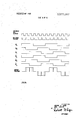
- FIG. 5 b is a diagram of the input and output signals to the FIG. 5 a three-phase inverter.
- FIG. I is a block diagram of a'polyphase motor control system 1 comprising differential summer 2 which receives an input signal on line 3 and'a signal on line 4 which is derived from' the output of polyphase motor 5.
- the output signal on line 4 is a DC voltage having a magnitude which is dependent on the speed of the rotor of the three-phase motor 5.
- the speed is sensed by sensor 6, which may be a magnetic pick or any other suitable device.
- the DC voltage is then summed with the input signal on line 3.
- the input signal on line 3 is a DC voltage although in other embodiments the input signal could be an AC signal. In the latter case, it would be necessary to Incorporate an AC to DC converter in the summer 2.
- the differential summer may be implemented by an integrated operational amplifier, the details of which are known to persons skilled in the art. In systems where a variable torque control is required, a second operational amplifier may be used.
- the DC output from summer 2 provides an input to voltagecontrolled oscillator (VCO) 7, which generates square wave pulses.
- VCO voltagecontrolled oscillator
- the square wave pulses have a frequency which is dependent upon the magnitude of the DC voltage generated by summer 2.
- the VCO generates an output pulse at a frequency six times the frequency of the motor. The frequency of the signal will become more significant during the descriptions of FIGS. 5 a and 5 b.
- Voltage-controlled oscillater 7 may be implemented by a unijunction oscillator or a flip-flop with a variable current source for changing the time constant of the circuit as a function of the input voltage. Other voltage-controlled oscillators could also be used.
- the squarewave pulses from the voltage-controlled oscillator 7 provides a clock signal input into three-phase signal generator 8 via line 9.
- the output from voltage-controlled oscillator 7 provides a trigger input to astable multivibrator 10 via line 11.
- the astable multivibrator l0, delay multivibrator 24 and oscillator 25 comprising control circuit 26 are described in more detail in FIG. 52.
- the three-phase generator may be implemented with three J-K flip-flops, as shown in FIG. 2 a.
- the output from the voltage-controlled oscillator on line 9 provides simultaneous clock inputs to flip-flops 13, I4 and 15 of three-phase generator 8.
- the outputs? e e,,'e',', e and are taken from the Q and Q outputs of the J-K fiip-flops.
- the six output lines are represented by line 16 in FIG. I.
- FIG. 2 b The wave forms of the outputs e, through 2 as well as the clock input from VCO, are shown in FIG. 2 b. As indicated in FIG. 2 a, e, e are I80 out of phase.
- the J-K flip-flops trigger on the leading edge of the clock signal.
- the frequency of the output signals from the three-phase generator 8 for the particular embodiment shown is seen to be one-sixth of the frequency of the clock signal on line 9.
- the three-phase clock signals from the flip-flops have a phase separation of 12. electrical degrees.
- the pulse width modulator I2 receives the six output signals from three phase generator 8 and varies the pulse width of each phase such that the voltage applied to motor increases as the frequency of the square wave voltage into the pulse width modulator increases until a maximum pulse width signal is generated.
- the pulse width decreases as the frequency decreases.
- the pulse width modulator may be implemented by six one-shot multivibrators for converting the input signals into 1 output signals. An example of one one-shot multivibrator is shown in FIG. 3.
- an input signal is received on line 17 .for turning on transistor 18.
- transistor 18 When transistor 18 is turned on,
- capacitor 19 is charged through resistor 20.
- the capacitor is permitted to charge as long as transistor 18 is turned on. Therefore, if the input voltage has a reduced width, the output voltage I on line 21 also has a reduced width.
- the circuit is designed so that for a maximum input voltage, determined as a function of the maximum speed of motor 5, a maximum 1 output signal will occur.
- each one shot multivibrator is said to be equal to one-half the period of the highest frequency at which the motor operates. For a 60 Hz. motor, the time period is 8.4 milliseconds; and for a 400 Hz. motor, the time period is l.25 milliseconds.
- Pulse width modulation is accomplished by the one-shot multivibrator by lowering the frequency of the input voltage. As the frequency of the input pulse decreases, the onperiod of the multivibrator relative to the true phase of the input signal decreases.
- the outputs from the pulsewidth modulator 12 provide inputs to three-phase bridge circuit 22 on lines represented generally by numeral 23.
- the three-phase bridge circuit 22 also receives inputs from 'astable multivibrator l0, delay multivibrator 24, and oscillator 25 when the three-phase bridge is implemented by silicon-controlled rectifiers as shown in FIG. 52. If the bridge is implemented by power transistors, the control circuit 26 may be eliminated.
- a simplified embodiment of the three-phase bridge is Sl'l0 Vn in FIG. 4 a.
- the th e-phase bridge 27 receives inputs I1 (IL, D I 4 and for generating stator drive signals for motor 5.
- the three-phase bridge comprises switches 28, 29,, 30, 31, 32, and 33 for switching the voltage E across the stator windings of motorJ under the control of the input signals 4 as shown in FIG. 4 b.
- the control d signals are spaced from each other by 120.
- the voltage across the windings is comprised of the sum of the E DC voltage as passed through the various switches for the true intervals of the control signals. For example, the voltage between terminals a and b is zero volts during the first 60 since 1 and I are both true. However, during the next 60,
- switch 31 turns on so'that E is dropped between terminals 0 and b. As shown in FIG. 4 b, e increases during the second and third 60 intervals. During the next 60 interval, E is also dropped between terminals 0 and b. However, during the next 60, switch 28 is turned off so that the voltage between terminals a and b drops to a zero reference. During the next 60, switch 29 and switch 30 are turned on so that for two consecutive 60 intervals, a negative voltage, e,,,,', is impressed across the windings. Thereafter, the cycle continues as previously described. A similar analysis could be made for the voltage between each of the terminals ac and be.
- FIG. 5 a illustrates a schematic diagram of a bridge network using silicon controlled rectifiers 35, 36, 37, 38, 39 and 40 as the switches controlled by phase signals 1 through D
- transistor 41 is turned on by the output signal from the voltage control oscillator which turns on silicon-controlled rectifier (SCR) 34.
- SCR silicon-controlled rectifier
- Pulse transformer 57 transfers the power to turn on SCR 34.
- SCR 34 turns on, a negative voltage appears at point 48 to black bias the bridge network comprising SCRs 35-40.
- transistor 49 is turned on to turn on SCR 50 for charging capacitor C1 from -E,,,.. Pulse transformer 58 transfersthe power.
- the charge of capacitor C1 turns on SCR 34 and permits the bridge network to operate.
- the SCRs are turned on and off every 60 electrical degrees of operation.
- the relationship between the VCO output, the delay pulse generated by multivibrator 24, the three phase signals D 1 and the summed voltage signal impressed across the stator windings of the motor are shown in FIG. 5 b.
- the turnoff period is shown every 60 by the motor voltage signal.
- SCRs 35-40 are similar to the operation previously described for the bridge network in FIG. 4 a.
- Each SCR is turned on at the appropriate time by the square wave voltages 1 applied to the base electrodes of the associated transistors.
- SCR '35 is turned on when the t rue ghase of D is applied to the base of transistor 42.
- Signals 4 r C are applied according to the sequence shown in FIG. 5 b to the bases of transistors 42-47 respectively.
- the high frequency astable multivibrator supplies collector current to transistor 41 by square wave pulses during the time that each of the transistors 42-47 is turned on by the output signals from the pulse width modulator.
- the pulses in the secondaries of each of the pulse transformers 51-56 assures that its associated SCR transfers power.
- the power from the SCRs is summed at terminals a, b and c to produce the signal across the motor shown in FIG. 5 b.
- the bridge network is turned off every 60.
- the dotted signal illustrates a reduced motor voltage.
- the voltage designated by the point x on the collectors of transistors 42-47 may be replaced by the output signal from the oscillator 25 which may be a kc. multivibrator.
- the transformers 51-58 (which isolate the SCR gates) may be implemented by relatively small pulse-type transformers. The pulse thus applied to the SCR gates would be a sharp rising wave front to insure turn on by the SCR. Under normal operation, however, a DC voltage is applied at point x.
- a system for controlling the speed of a polyphase motor comprising:
Landscapes
- Engineering & Computer Science (AREA)
- Power Engineering (AREA)
- Control Of Ac Motors In General (AREA)
Abstract
An input voltage is summed with a voltage picked off from a polyphase motor for driving a voltage-controlled oscillator. The frequency of the output signal from the oscillator is dependent on the magnitude of the summed voltage. The pulse width is modified within a predetermined range as a function of the frequency and is converted into three phase signals which are summed and applied to the stator windings of a motor. The signal across the windings has an optimum voltage and frequency ratio which is varied when the speed of the motor is changed.
Description
United States Patent IPPUT George A. Dyer Santa Ana Emil Kohler, Anaheim, Calif.
Sept. 26, 1969 May 4, 1971 North American Rockwell Corporation inventor Appl. No. Filed Patented Assignees SYSTEM FOR CONTROLLING THE SPEED OF A MOTOR UTILIZING PULSE WIDTH MODULATION 8 Claims, 8 Drawing Figs.
US. Cl 318/328, 318/329, 318/341 Int. Cl "02p 7/14 Field of Search l8/3 l 6,
DIFFERENTIAL SUMMER [56] References Cited UNITED STATES PATENTS 3,436,635 4/1969 James et al. Primary Examiner-Cris L. Rader Assistant Examiner-+1. Huberfeld Att0rneysL. Lee Humphries, H. Fredrick Hamann and Robert G. Rogers ABSTRACT: An input voltage is summed with a voltage picked off from a polyphase motor for driving a voltage-controlled oscillator. The frequency of the output signal from the oscillator is dependent on the magnitude of the summed voltage. The pulse width is modified within a predetermined range as a function of the frequency and is converted into three phase signals which are summed and applied to the stator windings of a motor. The signal across the windings has an optimum voltage and frequency ratio which is varied when the speed of the motor is changed.
PATENT-ED MAY 4197:
SHEET 2 OF 6 INVIZNTORS GEORGE A. DYER EMIL KOHLER ATTORNEY PATENTEU MAY 4 l9?! SHEET 3 0F 6 FIG. 3
IN VENTORS DYER R m AH o EK mL mm GE 5 m m" w m FW/V- L b 0.0
M B F ATTORNEY PATEN IEDMAY 4m! 3.577.057
snmu or 6 INVENTORS GEORGE A. DYER EMIL KOHLER MFA-91W ATTORNEY PATENIED m 4 I971 SHEET 5 BF 6 INVENTORS m: A. oven BY EMIL 'xonu-zn I ATTORNEY PATENIED HAY 41971 SHEET 8 0F 6 AsTAau: 7
OUTPUT DELAYED PULSES- IN VEN TORS GEORGE A DYER ATTORNEY BACKGROUND OF THE INVENTION 1. Field of the Invention The invention relates to a system for controlling the speed of a motor and, more particularly, to such a system in which the pulse width of a drive signal is modified within a predetermined range to provide a drive signal to a polyphase motor which has constant voltage/frequency ratios for various motor speeds.
2. Description of the Prior Art The need for new and improved motor speed control systems is described in US. Pat. No. 3,323,032, for an ELEC- TRICDRIVE SYSTEM by Paul D. Agarwal et al., issued May 30, I967 (CL. 318-321). I
.The patent describesa voltage-switching device used in a variable speed drive system for generating a plurality of differing voltage levels for controlling the performance of an AC motor. As shown in FIG. I of the patent, the system includes a DC source, a voltage switch which receives the DC source and thevoltage representing the motor position. The output from the voltage switch is converted into square wave signals by a static inverter for driving the motor. The different voltage levels are provided by the voltage switch.
A system is preferred in which variations in motor speed due to loading or changes in input voltages are detected and use to control the voltage/frequency ratio of the drive signals for the motor. The ratio should be constant for all values of motor speed so that the motor can perform according to its designed torque and speed. If the speed is controlled by a single variable such as frequency, the number of components, system size, weight and cost could be substantially reduced. The present invention provides such a system.
SUMMARY OF THE INVENTION Briefly, the invention comprises a system for controlling the speed of a polyphase motor operating from a DC or AC voltage input source. The invention comprises means for generating a signal having a frequency as a function of the difference between. an input voltage and the output voltage from the motor. The pulse width of the signal is modified over a predetermined frequency range.
Polyphase signals are generated from the modified pulse width signal and are selectively added to provide polyphase drive signals to the stator windings which have a constant voltage/frequency ratio for the various motor speeds involved. The range of operating motor speeds also determines the frequency range overwhich the pulse width of the above-mentioned signal can be modified. As a result, regardless of the speed desired, the voltage/frequency ratio is held constant. The frequency can be varied as a function of the desired speed by varying the input voltage. The voltage is held constant by the selective adding of the polyphase modified pulse width signals.
At relatively low motor speeds (and therefore relatively low frequency drive signals), a minumum average voltage is applied to the stator windings of the motor to provide a starting torque. In that case, the voltage/frequency ratio may be other than a constant for optimum operations.
Therefore, it is an object of this invention to provide an improved system for controlling the speed of a polyphase motor. It is another object of this invention to provide a system generating continuously variable drive signals for controlling the variable speed of a polyphase induction motor operating from a DC or AC voltage source.
It is another object of this invention to provide an improved motor speed control system in which the only variable of the system is frequency and in which voltage tracking for the motor is obtained without the need for a separately designe pulse width modulator circuit.
A still further object of the invention is to provide a polyphase motor speed control system having a relatively reduced overall size, weight, and cost.
A further object of the invention is to provide a polyphase motor speed control system in which the voltage/frequency ratio of the drive signals is held optimized constant by varying the frequency of a signal generated by turning on an input signal and a pickoff signal from the motor.
These and other objects of the invention will become more apparent when taken in connection with the description of drawings, a brief description of which follows:
BRIEF DESCRIPTION OF DRAWINGS FIG. 1 is a block diagram of one embodiment of the system for controlling the motor speed.
FIG. 2 a is a block diagram of a three-phase signal generator.
FIG. 2 b is an illustration of input and output signals of the FIG. 2 a generator.
FIG. 3 is a schematic diagram of a pulse width modulator.
FIG. 4 a is a schematic diagram of a three-phase bridge network. I
FIG. 4 b is an illustration of input and output signals from the FIG. 4 a network.
FIG. 5 a is a schematic diagram of one embodiment of a three-phase inverter.
FIG. 5 b is a diagram of the input and output signals to the FIG. 5 a three-phase inverter.
DESCRIPTION OF THE PREFERRED EMBODIMENT FIG. I is a block diagram of a'polyphase motor control system 1 comprising differential summer 2 which receives an input signal on line 3 and'a signal on line 4 which is derived from' the output of polyphase motor 5. The output signal on line 4 is a DC voltage having a magnitude which is dependent on the speed of the rotor of the three-phase motor 5.
The speed is sensed by sensor 6, which may be a magnetic pick or any other suitable device. The DC voltage is then summed with the input signal on line 3. In the preferred embodiment, the input signal on line 3 is a DC voltage although in other embodiments the input signal could be an AC signal. In the latter case, it would be necessary to Incorporate an AC to DC converter in the summer 2.
The differential summer may be implemented by an integrated operational amplifier, the details of which are known to persons skilled in the art. In systems where a variable torque control is required, a second operational amplifier may be used.
The DC output from summer 2 provides an input to voltagecontrolled oscillator (VCO) 7, which generates square wave pulses. The square wave pulses have a frequency which is dependent upon the magnitude of the DC voltage generated by summer 2. In one embodiment, the VCO generates an output pulse at a frequency six times the frequency of the motor. The frequency of the signal will become more significant during the descriptions of FIGS. 5 a and 5 b. Voltage-controlled oscillater 7 may be implemented by a unijunction oscillator or a flip-flop with a variable current source for changing the time constant of the circuit as a function of the input voltage. Other voltage-controlled oscillators could also be used.
The squarewave pulses from the voltage-controlled oscillator 7 provides a clock signal input into three-phase signal generator 8 via line 9. The output from voltage-controlled oscillator 7 provides a trigger input to astable multivibrator 10 via line 11. The astable multivibrator l0, delay multivibrator 24 and oscillator 25 comprising control circuit 26 are described in more detail in FIG. 52.
The clock signal transformed into three-phase signals by the three-phase generator 8 to provide six inputs to pulse width modulator 12. The three-phase generator may be implemented with three J-K flip-flops, as shown in FIG. 2 a.
As indicated in FIG. 2 a, the output from the voltage-controlled oscillator on line 9 provides simultaneous clock inputs to flip-flops 13, I4 and 15 of three-phase generator 8. The outputs? e e,,'e',', e and are taken from the Q and Q outputs of the J-K fiip-flops. The six output lines are represented by line 16 in FIG. I.
The wave forms of the outputs e, through 2 as well as the clock input from VCO, are shown in FIG. 2 b. As indicated in FIG. 2 a, e, e are I80 out of phase. The J-K flip-flops trigger on the leading edge of the clock signal.
The frequency of the output signals from the three-phase generator 8 for the particular embodiment shown is seen to be one-sixth of the frequency of the clock signal on line 9. The three-phase clock signals from the flip-flops have a phase separation of 12. electrical degrees.
The pulse width modulator I2 receives the six output signals from three phase generator 8 and varies the pulse width of each phase such that the voltage applied to motor increases as the frequency of the square wave voltage into the pulse width modulator increases until a maximum pulse width signal is generated. The pulse width decreases as the frequency decreases. The pulse width modulator may be implemented by six one-shot multivibrators for converting the input signals into 1 output signals. An example of one one-shot multivibrator is shown in FIG. 3.
As illustrated in FIG. 3, an input signal is received on line 17 .for turning on transistor 18. When transistor 18 is turned on,
The time period of each one shot multivibrator is said to be equal to one-half the period of the highest frequency at which the motor operates. For a 60 Hz. motor, the time period is 8.4 milliseconds; and for a 400 Hz. motor, the time period is l.25 milliseconds. Pulse width modulation is accomplished by the one-shot multivibrator by lowering the frequency of the input voltage. As the frequency of the input pulse decreases, the onperiod of the multivibrator relative to the true phase of the input signal decreases.
The outputs from the pulsewidth modulator 12 provide inputs to three-phase bridge circuit 22 on lines represented generally by numeral 23. The three-phase bridge circuit 22 also receives inputs from 'astable multivibrator l0, delay multivibrator 24, and oscillator 25 when the three-phase bridge is implemented by silicon-controlled rectifiers as shown in FIG. 52. If the bridge is implemented by power transistors, the control circuit 26 may be eliminated.
A simplified embodiment of the three-phase bridge is Sl'l0 Vn in FIG. 4 a. The th e-phase bridge 27 receives inputs I1 (IL, D I 4 and for generating stator drive signals for motor 5. The three-phase bridge comprises switches 28, 29,, 30, 31, 32, and 33 for switching the voltage E across the stator windings of motorJ under the control of the input signals 4 as shown in FIG. 4 b. The control d signals are spaced from each other by 120.
The voltage across the windings is comprised of the sum of the E DC voltage as passed through the various switches for the true intervals of the control signals. For example, the voltage between terminals a and b is zero volts during the first 60 since 1 and I are both true. However, during the next 60,
switch 31 turns on so'that E is dropped between terminals 0 and b. As shown in FIG. 4 b, e increases during the second and third 60 intervals. During the next 60 interval, E is also dropped between terminals 0 and b. However, during the next 60, switch 28 is turned off so that the voltage between terminals a and b drops to a zero reference. During the next 60, switch 29 and switch 30 are turned on so that for two consecutive 60 intervals, a negative voltage, e,,,,', is impressed across the windings. Thereafter, the cycle continues as previously described. A similar analysis could be made for the voltage between each of the terminals ac and be. It should be obvious that as the frequency of the I signals decreases, the width of the voltage pulse impressed across the windings also decreases. As the pulse width decreases, the speed of the motor decreases. Therefore, as the frequency output from the voltage control oscillator decreases, the width of the voltage pulse impressed across the windings of motor 5 also decreases to control the speed of the motor. Simultaneously, the average value of the voltage decreases so that a constant ratio of voltage/frequency is maintained.
FIG. 5 a illustrates a schematic diagram of a bridge network using silicon controlled rectifiers 35, 36, 37, 38, 39 and 40 as the switches controlled by phase signals 1 through D Initially, transistor 41 is turned on by the output signal from the voltage control oscillator which turns on silicon-controlled rectifier (SCR) 34. Pulse transformer 57 transfers the power to turn on SCR 34. When SCR 34 turns on, a negative voltage appears at point 48 to black bias the bridge network comprising SCRs 35-40. After a short delay produced by delay multivibrator 24, transistor 49 is turned on to turn on SCR 50 for charging capacitor C1 from -E,,,.. Pulse transformer 58 transfersthe power. The charge of capacitor C1 turns on SCR 34 and permits the bridge network to operate.
Since the frequency of the VCO is six times the frequency of the voltage applied across the motor windings, the SCRs are turned on and off every 60 electrical degrees of operation.
When the applied E is constant, the commutating circuit, I
comprising SCR 34, capacitor C1 and SCR 50, turns the SCR's in the bridge circuit on-and-off in time sequence with the leading and trailing edges from the output of the pulse width modulator 12. As a result, the average voltage applied to the SCR bridge is varied with applied frequency.
The relationship between the VCO output, the delay pulse generated by multivibrator 24, the three phase signals D 1 and the summed voltage signal impressed across the stator windings of the motor are shown in FIG. 5 b. The turnoff period is shown every 60 by the motor voltage signal.
The operation of SCRs 35-40 is similar to the operation previously described for the bridge network in FIG. 4 a. Each SCR is turned on at the appropriate time by the square wave voltages 1 applied to the base electrodes of the associated transistors. For example, SCR '35 is turned on when the t rue ghase of D is applied to the base of transistor 42. Signals 4 r C are applied according to the sequence shown in FIG. 5 b to the bases of transistors 42-47 respectively.
The high frequency astable multivibrator supplies collector current to transistor 41 by square wave pulses during the time that each of the transistors 42-47 is turned on by the output signals from the pulse width modulator. The pulses in the secondaries of each of the pulse transformers 51-56 assures that its associated SCR transfers power. The power from the SCRs is summed at terminals a, b and c to produce the signal across the motor shown in FIG. 5 b. As indicated by the signal, the bridge network is turned off every 60. The dotted signal illustrates a reduced motor voltage.
In certain embodiments, the voltage designated by the point x on the collectors of transistors 42-47 may be replaced by the output signal from the oscillator 25 which may be a kc. multivibrator. As a result, the transformers 51-58 (which isolate the SCR gates) may be implemented by relatively small pulse-type transformers. The pulse thus applied to the SCR gates would be a sharp rising wave front to insure turn on by the SCR. Under normal operation, however, a DC voltage is applied at point x.
We claim: 1. A system for controlling the speed of a polyphase motor, said system comprising:
means for generating a voltage representing the difference between a command speed for said motor and the actual speed of said motor, voltage-controlled oscillator means responsive to said voltage for generating a signal having a frequency as a function of said voltage, v means for generating polyphase signals from said signals, means for modifying. the pulse width of said polyphase signals as a function of the pulse width of said signal, said pulse widths being modifiable over a range of widths with the maximum limit being fixed by the maximum speed of said motor,
- polyphase bridge means for providing a drive signal to said motor under the control of said modified pulse width polyphase signals.
2. The combination recited in claim 1 wherein said means operating frequency of the motor for turning said bridge net;
work off every 60.
5. The combination recited in claim 1 wherein said polyphase bridge means includes a constant DC power pulse,
and wherein the leading and trailing edges of the modified pulse width signals turn said bridgemeans on-and-off for varying the average power across the bridge means.
6. The combination recited in claim 1 wherein said bridge means has a variable DC power source.
7. The combination recited in claim 1 wherein said system further. includes means for generating a signal to turn said bridge network off every 60 electrical degrees, and
means responsive to said signal for enabling a capacitor to be charged after a short delay,
means responsive to the capacitor voltage and said pulse width modified polyphase signals for supplying drive voltages to said motor.
8. The system recited in claim 7 further comprising a relatively high frequency signal generator means for providing an input to said bridge means to provide sharp turn on pulses for said bridge means.
Claims (8)
1. A system for controlling the speed of a polyphase motor, said system comprising: means for generating a voltage representing the difference between a command speed for said motor and the actual speed of said motor, voltage-controlled oscillator means responsive to said voltage for generating a signal having a frequency as a function of said voltage, means for generating polyphase signals from said signals, means for modifying the pulse width of said polyphase signals as a function of the pulse width of said signal, said pulse widths being modifiable over a range of widths with the maximum limit being fixed by the maximum speed of said motor, polyphase bridge means for providing a drive signal to said motor under the control of said modified pulse width polyphase signals.
2. The combination recited in claim 1 wherein said means for generating polyphase signals comprises a three-phase signal generator.
3. The combination recited in claim 2 wherein said means for modifying comprises a pulse width modulator for decreasing the width of said three phase signals from a maximum width representing the maximum speed of said motor to a minimum width representing the lowest operating speed of said motor.
4. The combination recited in claim 1 wherein said system further includes an oscillator responsive to said signal for generating a signal having a frequency six times that of the operating frequency of the motor for turning said bridge network off every 60*.
5. The combination recited in claim 1 wherein said polyphase bridge means includes a constant DC power pulse, and wherein the leading and trailing edges of the modified pulse width signals turn said bridge means on-and-off for varying the average power across the bridge means.
6. The combination recited in claim 1 wherein said bridge means has a variable DC power source.
7. The combination recited in claim 1 wherein said system further includes means for generating a signal to turn said bridge network off every 60 electrical degrees, and means responsive to said signal for enabling a capacitor to be charged after a short delay, means responsive to the capacitor voltage and said pulse width modified polyphase signals for supplying drive voltages to said motor.
8. The system recited in claim 7 further comprising a relatively high frequency signal generator means for providing an input to said bridge means to provide sharp turn on pulses for said bridge means.
Applications Claiming Priority (1)
| Application Number | Priority Date | Filing Date | Title |
|---|---|---|---|
| US86139769A | 1969-09-26 | 1969-09-26 |
Publications (1)
| Publication Number | Publication Date |
|---|---|
| US3577057A true US3577057A (en) | 1971-05-04 |
Family
ID=25335686
Family Applications (1)
| Application Number | Title | Priority Date | Filing Date |
|---|---|---|---|
| US3577057D Expired - Lifetime US3577057A (en) | 1969-09-26 | 1969-09-26 | System for controlling the speed of a motor utilizing pulse width modulation |
Country Status (1)
| Country | Link |
|---|---|
| US (1) | US3577057A (en) |
Cited By (17)
| Publication number | Priority date | Publication date | Assignee | Title |
|---|---|---|---|---|
| US3795848A (en) * | 1971-04-01 | 1974-03-05 | Buehler Gmbh Nachf Geb | Collectorless d. c. motor |
| US3971974A (en) * | 1973-05-09 | 1976-07-27 | Canon Kabushiki Kaisha | Apparatus for controlling the synchronous drive for direct-current motors |
| US4266432A (en) * | 1978-04-24 | 1981-05-12 | The Singer Company | Gyro motor control |
| US4513230A (en) * | 1980-04-17 | 1985-04-23 | General Electric Company | Laundering apparatus, method of operating a laundry machine, control system for an electronically commutated motor, and method of operating an electronically commutated motor |
| US4556827A (en) * | 1980-04-17 | 1985-12-03 | General Electric Company | Laundering apparatus, method of operating a laundry machine, control system for an electronically commutated motor, method of operating an electronically commutated motor, and circuit |
| US4686436A (en) * | 1984-07-06 | 1987-08-11 | General Electric Company | Electronic control circuit, electronically commutated motor system and method for controlling same, laundry apparatus, and methods for operating apparatus for switching high voltage DC and for controlling electrical load powering apparatus |
| US4788479A (en) * | 1985-11-22 | 1988-11-29 | Druckmaschinen AG Heidelberger | Control mechanism for a separately excited DC drive motor and method for control of a DC drive motor |
| US4859921A (en) * | 1988-03-10 | 1989-08-22 | General Electric Company | Electronic control circuits, electronically commutated motor systems, switching regulator power supplies, and methods |
| US5023527A (en) * | 1974-06-24 | 1991-06-11 | General Electric Company | Control circuits, electronically commutated motor systems and methods |
| US5075608A (en) * | 1974-06-24 | 1991-12-24 | Erdman David M | Control system, electronically commutated motor system, draft inducer apparatus and method |
| USRE35124E (en) * | 1974-06-24 | 1995-12-19 | General Electric Company | Control system, electronically commutated motor system, draft inducer apparatus and method |
| US5625265A (en) * | 1995-06-07 | 1997-04-29 | Kollmorgen Corporation | Compact, high efficiency electronic motor controller with isolated gate drive for power transistors |
| US5650709A (en) * | 1995-03-31 | 1997-07-22 | Quinton Instrument Company | Variable speed AC motor drive for treadmill |
| US5747955A (en) * | 1995-03-31 | 1998-05-05 | Quinton Instrument Company | Current sensing module for a variable speed AC motor drive for use with a treadmill |
| US5949202A (en) * | 1995-06-07 | 1999-09-07 | Kollmoregen Corporation | Distributed power supply for high frequency PWM motor controller with IGBT switching transistors |
| US6563283B2 (en) * | 2000-03-29 | 2003-05-13 | Fanuc Ltd. | Motor control device |
| US20050077848A1 (en) * | 2003-10-14 | 2005-04-14 | Baskin Brian L. | Pulse width modulator |
Citations (1)
| Publication number | Priority date | Publication date | Assignee | Title |
|---|---|---|---|---|
| US3436635A (en) * | 1965-09-02 | 1969-04-01 | Bendix Corp | Pulse width modulated servo drive control system |
-
1969
- 1969-09-26 US US3577057D patent/US3577057A/en not_active Expired - Lifetime
Patent Citations (1)
| Publication number | Priority date | Publication date | Assignee | Title |
|---|---|---|---|---|
| US3436635A (en) * | 1965-09-02 | 1969-04-01 | Bendix Corp | Pulse width modulated servo drive control system |
Cited By (18)
| Publication number | Priority date | Publication date | Assignee | Title |
|---|---|---|---|---|
| US3795848A (en) * | 1971-04-01 | 1974-03-05 | Buehler Gmbh Nachf Geb | Collectorless d. c. motor |
| US3971974A (en) * | 1973-05-09 | 1976-07-27 | Canon Kabushiki Kaisha | Apparatus for controlling the synchronous drive for direct-current motors |
| US5023527A (en) * | 1974-06-24 | 1991-06-11 | General Electric Company | Control circuits, electronically commutated motor systems and methods |
| USRE35124E (en) * | 1974-06-24 | 1995-12-19 | General Electric Company | Control system, electronically commutated motor system, draft inducer apparatus and method |
| US5075608A (en) * | 1974-06-24 | 1991-12-24 | Erdman David M | Control system, electronically commutated motor system, draft inducer apparatus and method |
| US4266432A (en) * | 1978-04-24 | 1981-05-12 | The Singer Company | Gyro motor control |
| US4556827A (en) * | 1980-04-17 | 1985-12-03 | General Electric Company | Laundering apparatus, method of operating a laundry machine, control system for an electronically commutated motor, method of operating an electronically commutated motor, and circuit |
| US4513230A (en) * | 1980-04-17 | 1985-04-23 | General Electric Company | Laundering apparatus, method of operating a laundry machine, control system for an electronically commutated motor, and method of operating an electronically commutated motor |
| US4686436A (en) * | 1984-07-06 | 1987-08-11 | General Electric Company | Electronic control circuit, electronically commutated motor system and method for controlling same, laundry apparatus, and methods for operating apparatus for switching high voltage DC and for controlling electrical load powering apparatus |
| US4788479A (en) * | 1985-11-22 | 1988-11-29 | Druckmaschinen AG Heidelberger | Control mechanism for a separately excited DC drive motor and method for control of a DC drive motor |
| US4859921A (en) * | 1988-03-10 | 1989-08-22 | General Electric Company | Electronic control circuits, electronically commutated motor systems, switching regulator power supplies, and methods |
| US5650709A (en) * | 1995-03-31 | 1997-07-22 | Quinton Instrument Company | Variable speed AC motor drive for treadmill |
| US5747955A (en) * | 1995-03-31 | 1998-05-05 | Quinton Instrument Company | Current sensing module for a variable speed AC motor drive for use with a treadmill |
| US5625265A (en) * | 1995-06-07 | 1997-04-29 | Kollmorgen Corporation | Compact, high efficiency electronic motor controller with isolated gate drive for power transistors |
| US5949202A (en) * | 1995-06-07 | 1999-09-07 | Kollmoregen Corporation | Distributed power supply for high frequency PWM motor controller with IGBT switching transistors |
| US6563283B2 (en) * | 2000-03-29 | 2003-05-13 | Fanuc Ltd. | Motor control device |
| US20050077848A1 (en) * | 2003-10-14 | 2005-04-14 | Baskin Brian L. | Pulse width modulator |
| US7006762B2 (en) * | 2003-10-14 | 2006-02-28 | Baskin Brian L | Pulse width modulator |
Similar Documents
| Publication | Publication Date | Title |
|---|---|---|
| US3577057A (en) | System for controlling the speed of a motor utilizing pulse width modulation | |
| US3512067A (en) | Speed regulation of asynchronous three-phase motors | |
| US3832625A (en) | Electrical power generating arrangement and method utilizing an induction generator | |
| US4377779A (en) | Pulse width modulated inverter machine drive | |
| US4328454A (en) | Apparatus for controlling ac motor | |
| US4546293A (en) | Motor control for a brushless DC motor | |
| US4320331A (en) | Transistorized current controlled pulse width modulated inverter machine drive system | |
| US3718847A (en) | Adjustable speed polyphase a-c motor drive utilizing an in-phase current signal for motor control | |
| US3940669A (en) | AC motor control system | |
| US3860858A (en) | Variable frequency inverter for ac induction motors with torque, speed and braking control | |
| US3170107A (en) | Controlled frequency alternating current system | |
| GB1559017A (en) | Motor control circuit | |
| US4792741A (en) | Control unit for non-circulating current type cycloconverter | |
| EP0202603B1 (en) | Cross coupled current regulator | |
| US3784888A (en) | Control for commutatorless motor | |
| US3027505A (en) | Motor control having rate feedback | |
| US3089992A (en) | Precision frequency control | |
| EP0000709A1 (en) | Measurement of pulsating torque in a current source inverter motor drive and method | |
| CA1155492A (en) | Apparatus for maintaining synchronism of an inverter-synchronous machine drive system at light or zero machine loads | |
| US3911339A (en) | Method for controlling the output condition of a synchronous reluctance motor | |
| US3538412A (en) | Motor control system with three phase conversion | |
| US4074174A (en) | Controlling apparatus for asynchronous motors with wound rotor | |
| US3445742A (en) | Control circuits for inverters producing an alternating output constituted by a pulse train | |
| US2995696A (en) | Alternating current generating system | |
| US3732472A (en) | Current supply and commutation circuit of electric motor |