United States Patent [72] Inventor [21 Appl. No. [22] Filed [45] Patented [73] Assignee Joseph A. Badali Branford, Conn. 763,566
Sept. 30, l 968 Mar. 9, 197 l Olin Corporation [54] SHOTGUN SHORT STROKE GAS SYSTEM 5 Claims, 4 Drawing Figs.
[52] US. Cl 89/191 [51] Int. Cl F41d 5/04 [50] Field ofSearch 89/191, 193, 159
[56] References Cited UNITED STATES PATENTS 2,582,989 1/1952 Harvey.... 89/l9lX 3,200,710 8/1965 Kelly et al 89/191 3,246,567 4/1966 Miller 89/191 3,386,336 6/1968 Roy 3,420,140 1/1969 Beretta Primary ExaminerBenjamin A. Borchelt Assistant ExaminerStephen C. Bentley Attorneys-William W. Jones, 11. Samuel Kieser, Donald R. Motsko, Richard S. Strickler, Robert H. Bachman and Thomas P. ODay ABSTRACT: A bolt-actuating gas system comprising an annular gas chamber, and annular piston, and an annular piston sleeve mounted on a tubular magazine wherein the piston, sleeve includes a push rod for contacting the bolt assembly.
The push rod contacts the bolt assembly but is not connected thereto so that when the piston is moved through its work stroke, the push rod drives against the bolt assembly to propel the latter toward its retired position. Furthermore, the bolt as sembly can be manually retracted to its retired position Without causing concurrent movement of the piston, sleeve androd.
Patented March 9, 1971 2 Sheets-Sheet l INVENTOR JOSEPH A. BAD/4L! ATTORNEY Patented March 9, '1971 2 Sheets-Sheet B INVENTOR JOSEPH A. BADAL/ BY Myr a:
ATTORNIz'Y l SHOTGUN SHORT STROKE GAS SYSTEM This invention relates to a short stroke gas system for use in actuating the bolt assembly of a firearm, such as a shotgumor the like.
Conventional gas operated shotguns have slide arms connnecting the piston the to bolt slide so that movement of the piston results in movement of the bolt assembly. When this type of gun is opened by hand, that is to say when the bolt assembly is manually retracted to its retired-position, the slide arms and piston move with the bolt assembly. As the gun gets dirty from repeated use, and as deposits form in the gas cylinder and'on the piston, the gun becomes more difficult to manually open;
A further disadvantage attendant to conventional gas operated shotguns lies in the exposure of the elements housed in the receiver to combustion gases when the gun is fired. As previously noted, the conventional gas operated shotgun in cludes at least one, and generally two slide arms which are connected to the bolt assembly and which are also generally connected to the gas'piston. Since the gas piston is positioned well forward on the gun, and the bolt assembly is rearward on the gun in the receiver, the slidearms-are of considerable length. The length of the conventional slide arms renders them flexible and subject tomeasurable bowing when the compressive force of the piston is applied to one end of the slide .arms when the gun is fired. In order to permit the slide'arms to move freely through the front wall of the of the receiver without jamming during actuation of the action of the conventional shotgun, sizeable apertures are cut through the front wall of the receiver. While the large apertures permit the slide arms to move freely through the front wall of the receiver, these apertures expose the various mechanical assemblies which are housed in the receiver to contaminated combustion gases which blow out of the gas cylinder toward the receiver. Exposure to these combustion gases causes undesirable deposits of material to form in the receiver, thus requiring periodic cleaning to remove these deposits.-
The gas system of this invention provides for a piston stroke which is shorter than the extent of movement of the bolt assembly during actuation of the latter. The gas system includes an annular bracket member mounted ,on the gun barrel and surrounding a portion of .a tubular cartridge magazine to define therewith an annular gas chamber. A ring-shaped piston member is slidably mounted on the magazine and disposed in the gas chamber, and a light weight piston sleeve member is connected to the piston and slidably mounted on the magazine to extend toward the receiver. A rigid push rod is connectedto the piston sleeve, the push rod extending rearward therefrom throughan aperture in the front wall of the receiver to a position adjacent the boltassembly. The rigidity of the rod permits the rod aperture to be only slightly larger than the outside diameter of the rod sothat a snug, sliding fit is achieved. The achievement of a snug fit between the rod and the aperture helps in greatly reducing ;the amount of combustion gas blow blown into the receiver. The bracket member includes lateral vents for exhausting combustion gases away from the receiver to further aid in reducing the amount of combustion gases blown into the receiver. A spring is mounted to bias the piston sleeve and piston toward the gas chamber. The push rod is not connected to the bolt assembly but is positioned next to the bolt assembly so that the rod is moved against the bolt assembly during the work stroke of the piston to begin movement of the bolt assembly toward its retired position after the gun is fired. The rod stops its rearward movement at the end of the work stroke of the piston, which occurs when the piston sleeve strikes the front face of the receiver, but the momentum imparted .to the bolt assembly from the rod causes the bolt assembly to move rearwardly to its retired position away from the rod. Thus the automatic actuation of the bolt assembly is accomplished without the use of slide arms, or the like, connected to the bolt, and with minimum exposure of the interior of the receiver to combustion gases. Also from the fact that the push rod is not connected to the bolt assembly, it is readily apparent that the bolt assembly can be manually retracted to its retired position without causing concurrent movement of the piston and piston sleeve.
It is, therefore, an object of this invention to provide a gas system for actuation of a bolt assembly in a semiautomatic shotgun, which gas system has a short stroke.
It is a further object of this invention to provide a gas system of the character described wherein the bolt assembly is unconnected to the bolt-actuating portion of the gas system.
It is yet another object of this invention to provide a gas system of the character described wherein the interior of the receiver portion of the gun is effectively sealed against penetration of gases from the gas chamber.
Other objects, advantages and features of the invention will become apparent to one skilled in the art from the following detailed descriptionwhen read in conjunction with the accompanying drawings, in which:
FIG. 1 is an explodedside .view of the various components of a. preferred embodiment of the gas system of this invention;
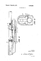
FIG. 2 is a side elevation, partially in section, of a portion of a shotgunincluding the gas system of FIG. 1, with the bolt assembly of the gun and the various movable components of the gas system disposed in their. normal positions prior to firing the FIG. 3 is a vertical. sectional view taken along line 3-3 of FIG. 2; and
FIG. 4 is a side elevation similar toFlG. 2, but showing the piston, piston sleeve, and push rod in their respectiverearwardmost positions with the bolt assembly immediately prior tomovement out of contact with the push rod.
Referring now to FIG. 1, a preferred embodiment of the gas system of this invention is shown. The system includesa conventional tubular magazine 2 which is mounted in any known manner beneath and parallel to the barrel of a shotgun. The forward end 4 of the magazine 2 is threaded to receive an end closure cap 6. "An annular bracket member 8 is mounted on the magazine 2, the bracket 8 having a first bore 10 of a predetermined smaller diameter which is snugly fitted against the outside surface of the magazine 2 so as to form a gastight seal therewith. The bracket 8 also includes a second bore 12 of a predetermined layer diameter which is spaced apart from the outside surface of the magazine 2'to define therewith a gas chamber 52 (see FIG..2). A plurality of lateral gas vents 14 are disposed in the wall of the bracket 8 in communication with the second bore 12. A laterally directed gas bleed port 16 is drilled through the wall of the bracket 8 to communicate with the second bore 12 at a location adjacent to the first bore 10.
An annular piston-member 18 having a first smaller bore 20 and a second larger bore 22 is slidably mounted on the magazine 2. An oblique face 24 is interposed between the bores 20 and 22, the face 24 preferably being formed at an angle of about 30 with the vertical. A pair of raised lands 26 are formed on the exterior of the piston 18 for gas sealing engagement with the larger bracket bore 12. A split ring 28 having an obliquely cut and face 30 and a normally cutface 32 is disposed within the piston bore 22, the face 30 being contiguous with the oblique piston face 24.
A lightweight annular piston sleeve 34 is slidably mounted on the magazine 2 and extends into the piston bore 22 to snugly engage the piston 18. The inner end 36 of the sleeve 34 is adjacent to the normal face 32 of the ring 28. A rigid push rod 38 is affixed to the sleeve 34 as by welding, or the like, the rod 38 extending beyond the outer end of the sleeve 34. A compressible spring 40 is mounted on the rod 38, the spring bearing against the front wall of the receiver on one hand, and bearing against the end wall 42 of a slot 44 cut into the sleeve 34 on the other hand.
Referring now to FIG. 2, the gas system of FIG. 1 is shown mounted on a shotgun (only partially shown). The bracket 8 is mounted below the gun barrel 46, and a port 48 is drilled through the barrel 46 into the barrel bore 50. The port 48 is aligned with the gas bleed port 16 to provide a passage through which pressurized combustion gases are bled from the bore 50 into the gas chamber 52. It is'noted that bracket 8, piston 18, piston sleeve 34, and magazine 2 are all disposed within a forearm 54 mounted on on the barrel 46. The magazine 2 is connected in any conventional manner to the receiver 56 of the shotgun. The bolt slide 58 is shown in FIG. 2
in bolt assemblys the battery position. The remaining portions of the bolt assembly are omitted for purposes of clarity, it being understood that the bolt may take any conventional form. It isfurther understood that the bolt assembly is biased by a spring (not shown) toward the battery position in a conventional manner. The push rod 38 extends through an aperture 60 in the front wall 62 of the receiver 56. The size of the aperture 60 has been greatly exaggerated in FIG, 2 for purposes of clarity, however, itis to be understood that the diameter of the aperture 60 is preferably only about 0.003 in.'
largerthan the diameter of the rod 38 so as to provide a snug gas sealing fit. The left hand end of the rod 38, as viewed in FIG. 2, is contiguous with the front face of the bolt slide-58. The bolt slide 58 is mounted for reciprocal movement on a pair of rails 64 in the receiver 56. g
' FIG. 3 shows the radial position of the various elements and the manner in which the push rod 38 contacts the'bolt slide 58. The bolt slide 58 is of sufficiently large mass to serve as an inertial body to continue rearward movement of the bolt assembly after the initial energy is supplied by the push rod 38.
FIG. 4 shows the actuating positions of the various members of the gas system when a shot charge is fired from the gun. The shot charge 66 is shown as his propelled down the barrel bore at a position downstream of the aligned gas bleed ports 16 and 48. High-pressure combustion gases are bled through the ports 16 and 48 into' the gas chamber 52. These high pressure gases cause the piston 18 to move through the bracket bore 12 toward the receiver 56, thus driving the piston sleeve 34 and rod 38. The end point of the work stroke of the piston 18 is reached when the piston sleeve 34 strikes the front wall 62 of the receiver 56, this position being shown in FIG. 4. It is noted that the spring 40 is compressed during the driving stroke of the piston 18. Movement of the piston 18 to the end point of its work stroke uncovers the gas vents 14 so as to vent the high pressure gases laterally out of the gas chamber 52 to lower the pressure therein.
As the piston 18 is driven through its work stroke, the split ring 28 flexes radially inwardly against the magazine 2, the tlexure resulting from the angular interface between the ring 28 and the piston face 24. The ring 28 thus provides a gastight seal between the piston 18 and the magazine 2, and also serves to scrape the magazine clean of any deposits during the work stroke of the piston. On the return stroke of the piston 18, the resiliency of the ring 28 causes it to flex back to its normal loose fit about the magazine 2, thus offering no impedance to the returning of the piston to its original position.
As previously noted, the mass of the bolt slide 58 is such that the bolt slide acts as an inertial body for the bolt assembly. Thus movement of the bolt assembly from the battery position to the position shown in FIG. 4 imparts sufficient momentum to the bolt assembly that the latter continues to move rearward in the receiver to its retired position, even though the push rod 38 ceases its rearward movement at the position shown in FIG. 4.
When the pressure in the gas chamber 52 has been sufficiently lowered, the spring 40 acts to return the piston 18, piston sleeve 34 and rod 38 to their original position (shown in FIG. 2), even as the bolt assembly continues its rearward movement to is its retired position.
It will be readily appreciated from the preceding that the gas system of this invention permits a short piston stroke, while at the same time provides for proper automatic actuation of the the bolt assembly of the firearm. Furthermore, it is readily apparent that the bolt assembly in a gun incorporating the' gas system of this invention can be manually retracted .to its retired position without concurrent movement of the piston,
sleeve, or rod occurring. The provision of a rigid push rod and gas vents in the gas system also presents a cleanly operating assembly hitherto unattainable in the gas systems of the prior art.
Since many changes and variations of the disclosed embodimerit of the-invention may be made without departing from the inventive concept, it is-not intended to limit the invention otherwise than as required by the appended claims.
Iclaim: v
1. In a semiautomatic firearm having a receiver, a barrel secured to the receiver, a-tubular magazine mounted adjacent and parallel to the barrel, and a bolt assembly reciprocally mounted in the receiver, a gas operated system for automatic reciprocation of said bolt assembly, said system comprising:
a. inertia means secured to said bolt assembly and contained wholly within said receiver;
b. bracket means secured to said barrel and surrounding a portion of said magazine, said bracket means having a wall radially spaced from said magazine to provide therewith a gas chamber;
0. port means interconnecting said gas chamber with a bore in said barrel;
d. annular piston means slidably mounted on said magazine and extending into said gas chamber, said piston means being movable through a relatively short work stroke and return; and
e. push means interposed between said piston means and said bolt assembly and extending through an aperture in said receiver, said push means being connected to said piston means and free of attachment with both said bolt assembly and said inertia means, said push means being operative to move against said bolt assembly and said inertia means to initiate reciprocation of 5 said bolt assembly when said piston means is driven through its work stroke, and to impart sufficient energy to said bolt assembly and said inertia means to cause the latter to continue reciprocation completely.
.2. The gas system of claim 1, further comprising spring means adjacent to said piston means and operative to move the latter and said push means through said return stroke.
3. The gas system of claim 1, wherein said piston means comprises lightweight stop means operative to stop movement of said piston means by impact with said receiver after said piston means has been driven through its work stroke and before said piston means completely exits said gas chamber, whereby a portion of said piston means always remains in said gas chamber during said work stroke.
4. The gas system of claim 1, wherein said push means is a rigid, substantially nonbendable rod, and said receiver aperture is of restricted size so as to provide a substantially leakproof gas seal with said rod to prevent entry of blowback gases into said receiver.
5. The gas system of claim 1, wherein said bracket means comprises at least one laterally directed vent operative to lower gas pressure in said gas chamber after said piston means has been moved through its work stroke.