US3537531A - Automatic guidance apparatus for vehicles - Google Patents
Automatic guidance apparatus for vehicles Download PDFInfo
- Publication number
- US3537531A US3537531A US746986A US3537531DA US3537531A US 3537531 A US3537531 A US 3537531A US 746986 A US746986 A US 746986A US 3537531D A US3537531D A US 3537531DA US 3537531 A US3537531 A US 3537531A
- Authority
- US
- United States
- Prior art keywords
- tractor
- plow
- machine
- steering
- sensing
- Prior art date
- Legal status (The legal status is an assumption and is not a legal conclusion. Google has not performed a legal analysis and makes no representation as to the accuracy of the status listed.)
- Expired - Lifetime
Links
Images


Classifications
-
- A—HUMAN NECESSITIES
- A01—AGRICULTURE; FORESTRY; ANIMAL HUSBANDRY; HUNTING; TRAPPING; FISHING
- A01B—SOIL WORKING IN AGRICULTURE OR FORESTRY; PARTS, DETAILS, OR ACCESSORIES OF AGRICULTURAL MACHINES OR IMPLEMENTS, IN GENERAL
- A01B69/00—Steering of agricultural machines or implements; Guiding agricultural machines or implements on a desired track
- A01B69/003—Steering or guiding of machines or implements pushed or pulled by or mounted on agricultural vehicles such as tractors, e.g. by lateral shifting of the towing connection
- A01B69/004—Steering or guiding of machines or implements pushed or pulled by or mounted on agricultural vehicles such as tractors, e.g. by lateral shifting of the towing connection automatic
-
- A—HUMAN NECESSITIES
- A01—AGRICULTURE; FORESTRY; ANIMAL HUSBANDRY; HUNTING; TRAPPING; FISHING
- A01B—SOIL WORKING IN AGRICULTURE OR FORESTRY; PARTS, DETAILS, OR ACCESSORIES OF AGRICULTURAL MACHINES OR IMPLEMENTS, IN GENERAL
- A01B69/00—Steering of agricultural machines or implements; Guiding agricultural machines or implements on a desired track
- A01B69/007—Steering or guiding of agricultural vehicles, e.g. steering of the tractor to keep the plough in the furrow
- A01B69/008—Steering or guiding of agricultural vehicles, e.g. steering of the tractor to keep the plough in the furrow automatic
Definitions
- An agricultural machine includes earthworking and tractive vehicle components, the vehicle component having a forward steerable wheel steered in relation to a guide line such as a furrow wall.
- a sensing device bearing against the furrow wall is sensitive to relative movement between the device and the steerable wheel, and actuates the steering mechanism to bring the front end of the machine and the sensing device back to a normal operating relation.
- another sensing device at the rear of the machine independently actuates the power steering to adjust the position of the vehicle and overcome the effects of sidehill drift.
- the present invention has for its object the provision of novel automatic guidance means for a tractor and implement combination including sensing means which is sensitive not only to change in direction of a selected guide line but also to lateral drifting of the rear end of the machine relative to its draft line or said guide line.
- Another object of the invention is the provision of guidance means for the steerable front wheels of an agricultural machine responsive to a guide line and additional guidance means compensating for side drift of the rear portion of the machine such as occurs when operating on hillsides.
- FIG. 1 is a diagrammatic side elevation with parts removed of an agricultural machine in the form of a tractor-plow combination on which is mounted automatic guidance mechanism incorporating the features of this invention
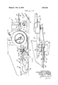
- FIG. 2 is an enlarged detail in side elevation of a portion of the guidance mechanism at the forward end of the machine and as indicated in FIG. 1;
- FIG. 3 is an enlarged detail in plan, with parts removed of the structure shown in FIG. 2;
- FIG. 4 is an enlarged plan view of a portion of the sensing mechanism at the rear of themachine
- FIG. 5 is an enlarged diagrammatic section taken on the line 5-5 of FIG. 3; and 1 FIG. 6 is a diagrammatic plan view of a pair ofcam-actuated switches controlling the operation of the power steering mechanism of the tractor.
- the numeral 10 designates an agricultural machine having aforward tractive vehicle component 11 and a rear connected earthworking component in the form of a moldboard plow 12 connected to the vehicle component or tractor by links 13.
- the tractor may take any suitable form, but is illustrated as having laterally spaced rear drive wheels 14 and a pair of steerable front wheels 15 supported by a rotatable vertical post 16 rotated to steer the front wheels by any suitable power operated steering means, not shown, controlled by the tractor operator through steering mechanism 17.
- the plow 12 is a conventional moldboard plow. for example of the semimounted type, adapted to establish a furrow. wall 18 which serves as a guide line for the machine as it traverses the field. A draft line is established for the machine by the connection between the vehicular and earthworking components.
- the links 13 are the lower links of a conventional tractor three-point hitch and may be raised and lowered through lift links 19 the upper ends of which are connected to rock arms 20 mounted on the tractor and operated preferably by hydraulic power to raise the front end of the plow.
- links 13 are pivotally connected to lugs 21 secured to a crossbar 22 to which is affixed a plate 23 carrying an upstanding spindle 24 upon which is pivotally received a bearing 25 carried by a transverse rail 26 forming part of the plow frame 27, one end of rail 26 being bent rearwardly and secured to the forward end of a diagonal supporting beam 28 upon which are mounted a plurality of plow bottoms 29.
- the draft load of the plow is taken on the spindle 24 which accommodates lateral swinging movement of the plowrelative to the tractor.
- the automatic guidance mechanism of this invention in cludes a forwardly disposed sensing device in the form of a disc 30, shown in FIG. I, engageable with the furrow wall 18 and carried at the end of a downwardly and rearwardly extending rod 31 mounted in a manner, not shown, at the end of a forwardly directed boom 32 and operatively connected by linkage such as that shown and described in the U.S. Pat. No. 3,402,784 filed Aug. 19, 1966, referred to above, to a rod 33
- Rod 31 is biased inwardly to hold disc 30 against the furrow wall, and movement of sensing disc 30 relative to the steerable wheels 15 due to veering of the furrow wall 18. for example, results in longitudinal movement of rod 33.
- Boom 32 is secured to and extends forwardly from a housing 34 supported at one end of a bracket 35 the other end of which is affixed to a plate 36 secured to the forward end of tractor 11.
- housing 34 In housing 34 is mounted an electrical signal trans mitting mechanism operated in response to the movement of rod 31 and disc 30 relative to the tractor, electric current being derived from a source of electricity of any well known form, not shown, carried by the tractor and operatively connected to the power operated steering mechanism of the tractor to turn the tractor wheels 15 to the left or to the right to effect corrective steering and return the tractor wheels to the selected position relative to furrow wall 18.
- Electrical switch and switch-actuating means is indicated by the numeral 37 and includes a vertical shaft 38 rotatable in a sleeve 39 which is rotatably mounted in housing 34, shaft 38 having affixed thereto a main plate 40 to which are secured a pair of vertically offset plates 41 and 42 upon which are mounted leftand right-hand electrical switches 43 and 44, respectively.
- Switches 43 and 44 are provided with spring closure fingers 45 and 46, respectively, having hook ends, and actuation of these switches is effected by the provision of a cam 47 affixed to the upper end of sleeve 39 and having actuating lobes .48 and 49 engageable with the hook ends of fingers 4S and 46.
- An intermediate control system is mounted on the tractor rearwardly of housing 34 wherein an" arm 52 is affixed to the lower end of sleeve 39 and is apertured to receive the downwardly bent end of a link 53, the other end of which is bent upwardly for pivotal connection to an arm 54 of a bellcrank 55 fulcrumed upon a pin 56 mounted on plate 36.
- One end of a bar 57 is pivoted on pin 56, and medially of its ends at 58 to one arm of a U-shaped link 59, the other end of which is connected to a plate 60 mounted on the rotatable steering post 16 of the tractorl
- Upon corrective turning of the tractor wheels 15 to the right bar 57 is swung clockwise, as viewed in FIG. 3, about the axis of pin 56 to which bellcrank 55 is pivotally affixed, swinging arm 54 and link 53 rearwardly.
- Arm 54 and bar 57 swing as a unit about the axis of pin 56 due to the presence of a Bowden wire 61 comprising a flexible sheath 62 secured at its forward end to bar 57 by clamp 63 and having a flexible shaft 64 slidably mounted therein and con nected to another arm 65 of bell crank 55.
- a Bowden wire 61 comprising a flexible sheath 62 secured at its forward end to bar 57 by clamp 63 and having a flexible shaft 64 slidably mounted therein and con nected to another arm 65 of bell crank 55.
- Bellcrank 55, bar 57 and shaft 64 form a relatively rigid triangle pivotable about pin 56 except when shaft 64 is independently telescoped in sheath 62, as will be explained hereinafter. 7
- the implement component in the form of moldboard plow 12 may tend to'drift downhill with respect to the tractor component 11.
- FIGS. 1 and 4 if we assume the plow drifting to the right with respect to the tractor, correction must be made in the steering of the tractor to bring the tractor and the implement back to an in-line or normal operating position.
- Rod 70 and disc 71 are biased downwardly and'inwardly by the provision of a spring 72, one end of which is mounted on the laterally projecting lower end of spindle 69.
- the upper end of spindle 69 has secured thereto an arm 73 to which is connected one end of a link 74 which may, if desired, be adjustable in length, and the other end of which is connected to one arm of a bellcrank 75, the otherarrn of which is connected to
- sensing disc 30 acts in the manner described through switches 43 and 44 to cause steering wheels to correctively turn to the right
- clockwise rotation of plate 60 acts through link 59, bar 57 and shaft 64 to swing member 55 clockwise, and through link 53 and arm 52 to revolve cam 47 counter clockwise and restore spring fingers 45 and 46 to the normal inactive position of FIG. 6. This cuts off the steering signal and permits the tractor wheels to proceed in normal spaced relation to furrow wall
- tractor wheels 15 to the left revolves plate 60 counterclockwise and, through connecting link 59, and by virtue of the rigidity of the parts 54, 57, and 64, revolving the latter as a unit about axis 56, and revolving shaft 38 and plate 40 clockwise to again open switch 43 and cancel the steering correction.
- said first sensing means being operatively connected to said power steering means for actuating the latter to adjust said steerable wheel in response to said relative movement of said firstsensing means, an intermediate control means operatively connected to said first sensing means and to said steerable wheel, a second sensing means carried'by the trailing implement in operative relation to said external guide line and deflectable in response to the lateral motion of the trailing implement relative to said draft line, said second sensing means being operatively connected to said control means and to the power steering means thereby interacting with said first sensing means to adjust said steerable wheel to compensate for said lateral motion of said trailing implement and return the latter to said draft line.
- the powered tractive vehicle is a tractor and the trailing implement is a plow or the like drawn by the tractor, said guide line being a furrow wall and said first and second sensing means being laterally movable devices yieldably held against the furrow wall.
- link means operatively connect said steerable wheel to said other of said members to move the latter relative to said one of said members to open said switch member in response to turning of said steerable wheel'.
- connection ofsaid second sensing means to said intermediate control means comprises a flexible thrust member including a flexible sheath and a flexible rod slidable therein extending from the plow to said intermediate control means for transmitting the deflection of said second sensing means thereto.
Landscapes
- Life Sciences & Earth Sciences (AREA)
- Engineering & Computer Science (AREA)
- Mechanical Engineering (AREA)
- Soil Sciences (AREA)
- Environmental Sciences (AREA)
- Guiding Agricultural Machines (AREA)
Description
United States Patent 1,113,494 10/1914 .Schlicht inventors Raymond C. Fischer;
Otto E. Johnson, l'linsdale; Gerald J. Tiedt,
La Grange, Illinois Appl. No. 746,986 Filed July 23, 1968 Patented Nov. 3, 1970 Assignee lnternatinal Harvester Company Chicago, Illinois a corporation of Delaware AUTOMATIC GUIDANCE APPARATUS FOR VEHICLES 8 Claims, 6 Drawing lgigs.
' 11.8. CI. 172/26 int. Cl. A0lb 69/00 Field of Search 172/6, 26; 180/79, 82 280/872 References Cited UNITED STATES PATENTS 1,390,419 9/1921 Zybach 172/26X 1,980,553 11/1934 Salisbury.... l72/26X 2,509,914 5/1950 Goodwinc 172/26X 3,402,784 9/1968 Roberson et al. 1. l72/6X Primary Examiner-Robert E. Pulfrey Assistant Examiner-James W. Peterson AttorneyNoel G. Artman ABSTRACT: An agricultural machine includes earthworking and tractive vehicle components, the vehicle component having a forward steerable wheel steered in relation to a guide line such as a furrow wall. A sensing device bearing against the furrow wall is sensitive to relative movement between the device and the steerable wheel, and actuates the steering mechanism to bring the front end of the machine and the sensing device back to a normal operating relation. To compensate for lateral drift of the rear portion of the machine particularly in sidehill operation, another sensing device at the rear of the machine independently actuates the power steering to adjust the position of the vehicle and overcome the effects of sidehill drift.
Patented Nov. 3, 1970 Sheet 1 of 4 W W On Q ATT4'Y Patented Nov. 3, 1970 Sheet ATTYQ ATT'Y Patented Nov. 3, 1970 Sheet.
. mt .N, N E 1w Patente d Nov. 3, 1970 Sheet FIGS.
INVENTORS RA YM 0ND c. FISCHER 0170 E. JOHNSON GERALD J. 7/501 ATT'Y AUTOMATIC GUIDANCE APPARATUS FOR VEHICLES BACKGROUND OF THE INVENTION This invention relates to agricultural machines and particularly to automatic guidance means therefor. More specifically, the invention concerns guidance means for a tractor and plow combination.
Automatic guidance means for implement propelling tractors wherein a sensing device or feeler travels alongside the tractor and bears, for example, against a furrow wall and transmits corrective steering signals to the tractor upon deflection of the sensing device, are old. Such a device is described and illustrated in U.S. Pat. No. 3,402,784 filed Aug. 19, 1966. Such devices have been successful under most conditions, but when operating on sidehills with a tractor drawn plow or the like they have failed to compensate for the tendency of the rear end of the machine, either tractor or plow or both, to drift laterally relative to the line followed by the steering wheel and the sensing device. Therefore, the present invention has for its object the provision of novel automatic guidance means for a tractor and implement combination including sensing means which is sensitive not only to change in direction of a selected guide line but also to lateral drifting of the rear end of the machine relative to its draft line or said guide line.
Another object of the invention is the provision of guidance means for the steerable front wheels of an agricultural machine responsive to a guide line and additional guidance means compensating for side drift of the rear portion of the machine such as occurs when operating on hillsides.
DESCRIPTION OF THE DRAWINGS FIG. 1 is a diagrammatic side elevation with parts removed of an agricultural machine in the form of a tractor-plow combination on which is mounted automatic guidance mechanism incorporating the features of this invention,
FIG. 2 is an enlarged detail in side elevation of a portion of the guidance mechanism at the forward end of the machine and as indicated in FIG. 1;
FIG. 3 is an enlarged detail in plan, with parts removed of the structure shown in FIG. 2;
FIG. 4 is an enlarged plan view of a portion of the sensing mechanism at the rear of themachine;
FIG. 5 is an enlarged diagrammatic section taken on the line 5-5 of FIG. 3; and 1 FIG. 6 is a diagrammatic plan view of a pair ofcam-actuated switches controlling the operation of the power steering mechanism of the tractor.
DESCRIPTION OF THE PREFERRED EMBODIMENT In the drawings the numeral 10 designates an agricultural machine having aforward tractive vehicle component 11 and a rear connected earthworking component in the form of a moldboard plow 12 connected to the vehicle component or tractor by links 13.
The tractor may take any suitable form, but is illustrated as having laterally spaced rear drive wheels 14 and a pair of steerable front wheels 15 supported by a rotatable vertical post 16 rotated to steer the front wheels by any suitable power operated steering means, not shown, controlled by the tractor operator through steering mechanism 17. I
The plow 12, only the forward portion of which is shown, is a conventional moldboard plow. for example of the semimounted type, adapted to establish a furrow. wall 18 which serves as a guide line for the machine as it traverses the field. A draft line is established for the machine by the connection between the vehicular and earthworking components. It may be understood that the links 13 are the lower links of a conventional tractor three-point hitch and may be raised and lowered through lift links 19 the upper ends of which are connected to rock arms 20 mounted on the tractor and operated preferably by hydraulic power to raise the front end of the plow.
The rear ends of links 13 are pivotally connected to lugs 21 secured to a crossbar 22 to which is affixed a plate 23 carrying an upstanding spindle 24 upon which is pivotally received a bearing 25 carried by a transverse rail 26 forming part of the plow frame 27, one end of rail 26 being bent rearwardly and secured to the forward end of a diagonal supporting beam 28 upon which are mounted a plurality of plow bottoms 29. The draft load of the plow is taken on the spindle 24 which accommodates lateral swinging movement of the plowrelative to the tractor.
The automatic guidance mechanism of this invention in cludes a forwardly disposed sensing device in the form of a disc 30, shown in FIG. I, engageable with the furrow wall 18 and carried at the end of a downwardly and rearwardly extending rod 31 mounted in a manner, not shown, at the end of a forwardly directed boom 32 and operatively connected by linkage such as that shown and described in the U.S. Pat. No. 3,402,784 filed Aug. 19, 1966, referred to above, to a rod 33 Rod 31 is biased inwardly to hold disc 30 against the furrow wall, and movement of sensing disc 30 relative to the steerable wheels 15 due to veering of the furrow wall 18. for example, results in longitudinal movement of rod 33.
Electrical switch and switch-actuating means is indicated by the numeral 37 and includes a vertical shaft 38 rotatable in a sleeve 39 which is rotatably mounted in housing 34, shaft 38 having affixed thereto a main plate 40 to which are secured a pair of vertically offset plates 41 and 42 upon which are mounted leftand right-hand electrical switches 43 and 44, respectively.
Should the furrow wall 18 veer to the right, for example, movement of rod 31 outwardly against its bias will move rod 33 forwardly. The rear end of rod 33 is connected by pivot pin 50 with an arm 51 secured to the upper end of shaft 38. Thus, forward movement of rod 33 rotates shaft 38 and switch carrying plate 40 counterclockwise. Rotation of plate 40 counterclockwise causes the end of spring finger 46 to ride upon cam lobe 49 and close switch 44 directing a signal to the power steering mechanism of the tractor to turn wheels 15 to the right, toward the furrow.
An intermediate control system is mounted on the tractor rearwardly of housing 34 wherein an" arm 52 is affixed to the lower end of sleeve 39 and is apertured to receive the downwardly bent end of a link 53, the other end of which is bent upwardly for pivotal connection to an arm 54 of a bellcrank 55 fulcrumed upon a pin 56 mounted on plate 36. One end of a bar 57 is pivoted on pin 56, and medially of its ends at 58 to one arm of a U-shaped link 59, the other end of which is connected to a plate 60 mounted on the rotatable steering post 16 of the tractorl Upon corrective turning of the tractor wheels 15 to the right bar 57 is swung clockwise, as viewed in FIG. 3, about the axis of pin 56 to which bellcrank 55 is pivotally affixed, swinging arm 54 and link 53 rearwardly.
Bellcrank 55, bar 57 and shaft 64 form a relatively rigid triangle pivotable about pin 56 except when shaft 64 is independently telescoped in sheath 62, as will be explained hereinafter. 7
As pointed out hereinbefore, when operating a machine of this type, particularly on sidehills, the implement component in the form of moldboard plow 12 may tend to'drift downhill with respect to the tractor component 11. With respect to FIGS. 1 and 4 if we assume the plow drifting to the right with respect to the tractor, correction must be made in the steering of the tractor to bring the tractor and the implement back to an in-line or normal operating position.
In order to accomplish this the rear end of sheath 62' of Bowden'wire tilisanchored by a clamp 66 to a brace 67 secured to and extending forwardly and laterally from plow rail 26 and supporting at its end a bracket 68 in which is rotatably mounted a vertical spindle 69. The lower end of spindle 69 is bent outwardly and has pivotally mounted thereon the upper end of a supporting rod 70 for a sensing disc 71 engageable with the furrow wall 18 in the manner of the forward disc 30.
Rod 70 and disc 71 are biased downwardly and'inwardly by the provision of a spring 72, one end of which is mounted on the laterally projecting lower end of spindle 69. The upper end of spindle 69 has secured thereto an arm 73 to which is connected one end of a link 74 which may, if desired, be adjustable in length, and the other end of which is connected to one arm of a bellcrank 75, the otherarrn of which is connected to In operation, as previously noted Withres'p ect to the forward end of the machine, should the furrow wall-18 veer to the right, sensing disc 30 acts in the manner described through switches 43 and 44 to cause steering wheels to correctively turn to the right, clockwise rotation of plate 60 acts through link 59, bar 57 and shaft 64 to swing member 55 clockwise, and through link 53 and arm 52 to revolve cam 47 counter clockwise and restore spring fingers 45 and 46 to the normal inactive position of FIG. 6. This cuts off the steering signal and permits the tractor wheels to proceed in normal spaced relation to furrow wall 18.
With the front end of the machine operating normally with respect to furrow wall l8 and with the steering control switches 43 and 44 in theposition of FIG 6, and if wejassume, for example, that the machine is operating on a side hill wherein the tendency for the rear end of the tractor or the plow is to drift to the right, disc 71 will be urged inwardly by spring 72 causing arm 73 and rod 74 to turn bellcrank 75 in a clockwise direction. This moves shaft 64 forwardly in sheath 62 to rock member 55 in a clockwise direction independently of bar 57, revolving cam 47 counterclockwise causing cam lobe 48 to close switch 43 and actuate the power steering of the tractor to correctively steer the tractor wheels to the left to compensate for the side drift of the rear end of the machine.
. Turning tractor wheels 15 to the left revolves plate 60 counterclockwise and, through connecting link 59, and by virtue of the rigidity of the parts 54, 57, and 64, revolving the latter as a unit about axis 56, and revolving shaft 38 and plate 40 clockwise to again open switch 43 and cancel the steering correction.
it is believed that the construction and operation of the novel guidance mechanism of the present invention will be clearly understood from the foregoing description.
We claim: l
l. in an agricultural system including a powered tractive vehicle having power steering means and a forward steerable wheel, a trailing implement pivotally connected to the rear of the rear end of shaft 64 of Bowden wire 61, as shown in FIG.
switch member.
ried by a forward portion of the tractive vehicle inoperative relation to an external guide line substantially parallel to the path of said steerable wheel and deflectable from a normal position relative to said steerable wheel, said first sensing means being operatively connected to said power steering means for actuating the latter to adjust said steerable wheel in response to said relative movement of said firstsensing means, an intermediate control means operatively connected to said first sensing means and to said steerable wheel, a second sensing means carried'by the trailing implement in operative relation to said external guide line and deflectable in response to the lateral motion of the trailing implement relative to said draft line, said second sensing means being operatively connected to said control means and to the power steering means thereby interacting with said first sensing means to adjust said steerable wheel to compensate for said lateral motion of said trailing implement and return the latter to said draft line.
2. The invention set forth in claim 1, wherein the powered tractive vehicle is a tractor and the trailing implement is a plow or the like drawn by the tractor, said guide line being a furrow wall and said first and second sensing means being laterally movable devices yieldably held against the furrow wall.
3. The invention set forth in claim 2, wherein an electric switch member and a switch-actuating member are mounted on the tractor for movement of one relative to the other, said first sensing means being operatively connected to one of said members for moving it re'lative to the other of said members in response to the deflection of said first sensing means to close said switch member, said switch member being operatively connected tosaid power steering means to activate the latter to turn the steerable wheel 'in response to said closing of said 4. The invention set forth 'in'claim ,3, wherein said intermediate control means is responsive to the turning of said steerable wheel to move the otherof said members relative to said one of said members to open said switchmember and deactivate said power steering means.
5. The invention set forth in claim 4, wherein link means operatively connect said steerable wheel to said other of said members to move the latter relative to said one of said members to open said switch member in response to turning of said steerable wheel'.
6. The invention set forth in claim 2, wherein said second sensing means is mounted on a forward portion of the plow and extends forwardly therefrom alongside the tractor for operative connection to said intermediate control means.
7. The invention set forth in claim 6, wherein the connection ofsaid second sensing means to said intermediate control means comprises a flexible thrust member including a flexible sheath and a flexible rod slidable therein extending from the plow to said intermediate control means for transmitting the deflection of said second sensing means thereto.
8. The invention set forth in claim 7, wherein an electric switch member and a switch-actuating member are mounted on the tractor for movement of one relative to the other, said intermediate control means being operatively connected to one of said members for moving it relative to the other of said members in response to the deflection of said second sensing means to close said switch member, said first sensing means being operatively connected to the other of said members to close said switch member in response to the deflection of said first sensing means, said switch member being operatively connected to said power steering means to activate the latter to turn said steerable wheel in response to said closing of said switch member.
Applications Claiming Priority (1)
| Application Number | Priority Date | Filing Date | Title |
|---|---|---|---|
| US74698668A | 1968-07-23 | 1968-07-23 |
Publications (1)
| Publication Number | Publication Date |
|---|---|
| US3537531A true US3537531A (en) | 1970-11-03 |
Family
ID=25003189
Family Applications (1)
| Application Number | Title | Priority Date | Filing Date |
|---|---|---|---|
| US746986A Expired - Lifetime US3537531A (en) | 1968-07-23 | 1968-07-23 | Automatic guidance apparatus for vehicles |
Country Status (2)
| Country | Link |
|---|---|
| US (1) | US3537531A (en) |
| GB (1) | GB1271957A (en) |
Cited By (15)
| Publication number | Priority date | Publication date | Assignee | Title |
|---|---|---|---|---|
| US3785564A (en) * | 1972-07-07 | 1974-01-15 | A Baldocchi | Apparatus for treating rows of plants with overlapping branches |
| US3844372A (en) * | 1973-12-13 | 1974-10-29 | D Neece | Automatically guided tractor |
| US4180133A (en) * | 1978-01-12 | 1979-12-25 | Iowa State University Research Foundation, Inc. | Guidance system for towed vehicles |
| EP0023142A1 (en) * | 1979-07-20 | 1981-01-28 | Brouwer Turf Equipment Limited | Sod processing machine and shoe |
| US4366756A (en) * | 1980-09-09 | 1983-01-04 | Geosource Inc. | Electronic tractor guidance system |
| US4414903A (en) * | 1977-03-21 | 1983-11-15 | Pathfinder Systems, Inc. | Automatic guidance mechanism |
| US4640365A (en) * | 1985-04-24 | 1987-02-03 | Schmidt Eugene H | Row following guidance device for a tractor-drawn row crop implement |
| US4930581A (en) * | 1988-05-10 | 1990-06-05 | Fleischer Manufacturing, Inc. | Guidance control apparatus for agricultural implement |
| USRE34080E (en) * | 1985-04-24 | 1992-09-29 | New Tek Manufacturing, Inc. | Row following guidance device for a tractor-drawn row crop implement |
| US5240079A (en) * | 1990-06-04 | 1993-08-31 | A.I.L., Inc. | Guidance control system for farm tractor/implement combination having improved turnaround capability |
| US6478252B1 (en) * | 1988-02-16 | 2002-11-12 | Dunlop Ltd. | Aircraft braking systems |
| EP1688027A1 (en) * | 2005-02-07 | 2006-08-09 | CLAAS Selbstfahrende Erntemaschinen GmbH | Automatically steered agricultural vehicle |
| EP1776851A1 (en) * | 2005-10-18 | 2007-04-25 | Aad Klompe | Arrangement to control automatically the working width of a plough |
| GB2468123A (en) * | 2009-02-25 | 2010-09-01 | Agco Sa | Offset plough guidance system and apparatus |
| US10793186B2 (en) | 2018-01-11 | 2020-10-06 | International Business Machines Corporation | Steering assistance based on driver analytics and behavior |
-
1968
- 1968-07-23 US US746986A patent/US3537531A/en not_active Expired - Lifetime
-
1969
- 1969-07-22 GB GB36706/69A patent/GB1271957A/en not_active Expired
Cited By (15)
| Publication number | Priority date | Publication date | Assignee | Title |
|---|---|---|---|---|
| US3785564A (en) * | 1972-07-07 | 1974-01-15 | A Baldocchi | Apparatus for treating rows of plants with overlapping branches |
| US3844372A (en) * | 1973-12-13 | 1974-10-29 | D Neece | Automatically guided tractor |
| US4414903A (en) * | 1977-03-21 | 1983-11-15 | Pathfinder Systems, Inc. | Automatic guidance mechanism |
| US4180133A (en) * | 1978-01-12 | 1979-12-25 | Iowa State University Research Foundation, Inc. | Guidance system for towed vehicles |
| EP0023142A1 (en) * | 1979-07-20 | 1981-01-28 | Brouwer Turf Equipment Limited | Sod processing machine and shoe |
| US4366756A (en) * | 1980-09-09 | 1983-01-04 | Geosource Inc. | Electronic tractor guidance system |
| US4640365A (en) * | 1985-04-24 | 1987-02-03 | Schmidt Eugene H | Row following guidance device for a tractor-drawn row crop implement |
| USRE34080E (en) * | 1985-04-24 | 1992-09-29 | New Tek Manufacturing, Inc. | Row following guidance device for a tractor-drawn row crop implement |
| US6478252B1 (en) * | 1988-02-16 | 2002-11-12 | Dunlop Ltd. | Aircraft braking systems |
| US4930581A (en) * | 1988-05-10 | 1990-06-05 | Fleischer Manufacturing, Inc. | Guidance control apparatus for agricultural implement |
| US5240079A (en) * | 1990-06-04 | 1993-08-31 | A.I.L., Inc. | Guidance control system for farm tractor/implement combination having improved turnaround capability |
| EP1688027A1 (en) * | 2005-02-07 | 2006-08-09 | CLAAS Selbstfahrende Erntemaschinen GmbH | Automatically steered agricultural vehicle |
| EP1776851A1 (en) * | 2005-10-18 | 2007-04-25 | Aad Klompe | Arrangement to control automatically the working width of a plough |
| GB2468123A (en) * | 2009-02-25 | 2010-09-01 | Agco Sa | Offset plough guidance system and apparatus |
| US10793186B2 (en) | 2018-01-11 | 2020-10-06 | International Business Machines Corporation | Steering assistance based on driver analytics and behavior |
Also Published As
| Publication number | Publication date |
|---|---|
| GB1271957A (en) | 1972-04-26 |
Similar Documents
| Publication | Publication Date | Title |
|---|---|---|
| US3537531A (en) | Automatic guidance apparatus for vehicles | |
| US3061020A (en) | Semi-mounted farm implement with automatically steered rear wheel | |
| US3402784A (en) | Tractor guidance apparatus | |
| US3548966A (en) | Automatic steering means for an agricultural tractor | |
| US2627797A (en) | Gauge means for implements | |
| US2179793A (en) | Ridge leveling attachment for tractor cultivators | |
| US4161986A (en) | Plow and plow mounting bracket therefor | |
| US3387665A (en) | Automatic steering apparatus for implements | |
| US2644385A (en) | Reversing and leveling means for two-way plows | |
| US2247680A (en) | Agricultural implement | |
| US3516500A (en) | Trailing ploughs | |
| US3532172A (en) | Semi-mounted plow with caster wheel that can be tilted and locked for plowing | |
| US3481406A (en) | Semintegral two-way plow with offset steerable tail wheel | |
| US4135582A (en) | Plough | |
| US3625294A (en) | Steerable rear wheel for plow | |
| US1671507A (en) | Tractor cultivator | |
| US3321029A (en) | Hydraulically controlled plow | |
| US2205403A (en) | Steering mechanism for agricultural implements | |
| US2220361A (en) | Sidehill steering attachment for tractors | |
| US1916547A (en) | Tractor guide | |
| US2555555A (en) | Two-way plow | |
| US2943688A (en) | Reversible plow and gauge wheels | |
| US3326301A (en) | Front-mounted plow | |
| US1952496A (en) | Furrow guide for tractors | |
| US3101787A (en) | Marker shifting device for an agricultural implement |
Legal Events
| Date | Code | Title | Description |
|---|---|---|---|
| AS | Assignment |
Owner name: J.I. CASE COMPANY A DE CORP Free format text: ASSIGNMENT OF ASSIGNORS INTEREST.;ASSIGNOR:INTERNATIONAL HARVESTER COMPANY A DE CORP;REEL/FRAME:004379/0536 Effective date: 19850131 |