US3445019A - Fork lift truck having a lifting device mounted for pivotal movement about a vertical pivotal axle - Google Patents
Fork lift truck having a lifting device mounted for pivotal movement about a vertical pivotal axle Download PDFInfo
- Publication number
- US3445019A US3445019A US547864A US3445019DA US3445019A US 3445019 A US3445019 A US 3445019A US 547864 A US547864 A US 547864A US 3445019D A US3445019D A US 3445019DA US 3445019 A US3445019 A US 3445019A
- Authority
- US
- United States
- Prior art keywords
- lift truck
- fork
- lifting
- outrigger
- lifting device
- Prior art date
- Legal status (The legal status is an assumption and is not a legal conclusion. Google has not performed a legal analysis and makes no representation as to the accuracy of the status listed.)
- Expired - Lifetime
Links
Images


Classifications
-
- B—PERFORMING OPERATIONS; TRANSPORTING
- B66—HOISTING; LIFTING; HAULING
- B66F—HOISTING, LIFTING, HAULING OR PUSHING, NOT OTHERWISE PROVIDED FOR, e.g. DEVICES WHICH APPLY A LIFTING OR PUSHING FORCE DIRECTLY TO THE SURFACE OF A LOAD
- B66F9/00—Devices for lifting or lowering bulky or heavy goods for loading or unloading purposes
- B66F9/06—Devices for lifting or lowering bulky or heavy goods for loading or unloading purposes movable, with their loads, on wheels or the like, e.g. fork-lift trucks
- B66F9/075—Constructional features or details
- B66F9/08—Masts; Guides; Chains
- B66F9/10—Masts; Guides; Chains movable in a horizontal direction relative to truck
Definitions
- Sheet 2 May 20, 1969 K. STEINERT FORK LIFT TRUCK HAVING A LIFTING DEVICE MOUNTED FOR PI OTAL MOVEMENT ABOUT A VERTICAL PIVOTAL AXLE Flled May 5, 1966 May 20, 1969 K. STEINERT 3,445,019
- a fork lift truck capable of both front and side operations in which the vehicle is C-shaped in its ground plan and the lifting means is slewable about a vertical pivotal axle arranged at or adjacent an inner corner of the vehicle.
- the lifting means is linked with the vertical pivotal axle via an outrigger allowing horizontal displacement of the lifting means relative to the pivotal axle.
- This invention relates to vehicles for handling materials and more particularly to fork lift trucks.
- Fork lift trucks are constructed as front fork lift trucks as well as side fork lift trucks, and in view of the limited possibility of employing each of both types of fork lift trucks, there have heretofore been constructed so-called universal lift trucks which are intended to permit a front operation as well as a side operation.
- a known structural type of such universal lift trucks virtually constitutes nothing more than a front lift truck, the lifting device of which can be pivoted about a vertical pivotal axle. While it is true that in this manner it is possible that the load which can be lifted and lowered in a front operation is now put down laterally upon the platform of the lift truck, but a proper side operation is nevertheless impossible with this known vehicle.
- This lift truck is disadvantageous due to the great breadth of the vehicle at the front operation-i.e., when the vehicle is travelling transversely. Pivoting the load with respect to the vehicle is impossible with this type of lift truck.
- the object of this invention is to provide a fork lift truck which can be employed for front service as well as for a genuine side service, and which moreover permits the load to be put down onto the vehicle platform, and which also permits alternate operation, i.e., a frontside lifting and a sidewise lowering of the load and vice-versa, respectively.
- the invention originates from a fork lift truck having a lifting device mounted for pivotal movement about a vertical pivotal axle
- the present fork lift truck is characterized in that such pivotal axle is arranged at or adjacent an inner corner of the side-recess of the vehicle which, in its ground plan, is C-shaped in a manner known per se, and in that the lifting device is linked with such pivotal axle by means of a cantilever arm, for example, lazy tongs, permitting a horizontal displacement of the lifting device also known per se.
- a frame in which the lifting mast underpart guiding the vertically movable lifting mast extension together with the lifting slide which also is vertically movable therein, for its part is, again vertically "ice movable and moreover optionally laterally movable in such a manner that the lower edge of the lifting mast underpart can be lowered from a normal position substantially directly above the plane of the lift truck platform into a lowermost position substantially touching the path of travel or roadway.
- the lifting mast extension is extensible from a normal position upwardly as well as downwardly with respect to the lifting mast underpart guiding the lifting mast extension and optionally laterally movably mounted on the free end of the horizontally extensible outrigger, with such normal position being determined by the lower edge of the lifting mast underpart, and which lower edge is disposed substantially directly above the plane of the platform of the lift truck.
- the horizontally extensible outrigger is preferably extensible so far that it is swingable also when the parts of the lifting device are lowered beneath the plane of the platform of the vehicle.
- the outer corner of the vehicle that lies in the pivotal range of the horizontally extensible outrigger holding the lifting device may be flattened or rounded-off in its ground plan.
- the pivotal movements and/or the horizontal extension of the outrigger takes place preferably by virtue of a drive by fluid under pressure and an interlocking device, e.g., a cam plate, cooperating with feeler members of the horizontal outrigger can be provided on the vertical pivotal axis to prevent any components of the lifting device from being lowered underneath the plane of the platform of the lift truck so long as the lifting device is within the range of the ground plan of the vehicle.
- an interlocking device e.g., a cam plate
- FIGURE 1 is a ground plan of the fork lift truck according to the invention in the side operative position;
- FIGURE 2 is a ground plan of the fork lift truck of FIGURE 1, now in the front operative position;
- FIGURE 3 is a front view of the fork lift truck of FIGURES 1 and 2 in the side operative position
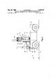
- FIGURE 4 is a side View of the fork lift truck of FIGURES 1 and 3 in the front operative position.
- a vehicle body 1, which substantially includes the travelling gear, the vehicle frame and the vehicle platform, of the present fork lift truck is, in its ground plan, similar to the ground plan of a known lateral lift truck, i.e., the ground plan of the vehicle is substantially C-shaped, whereby in the vehicle is formed a side-recess 2 receiving the lifting device of the fork lift truck during side operation.
- a vertical pivotal axle 3 known per se for the lifting device is arranged at or adjacent to an inner corner of the side-recess 2.
- the vertical pivotal axle 3 is located at the inner corner of the side-recess 2 of the lift truck, namely at a corner adjacent to the drivers cab indicated at 4 and arranged at the front side of the vehicle.
- the forward direction of travel is indicated by an arrow A in FIG- URES l, 2 and 4.
- the vertical pivotal axle 3 is preferably arranged again at the forward comer of the recess but at the forward corner opposite the drivers cab so that the driver can observe the work of the lift truck fork also during side operation.
- the vertical pivotal axle 3 constitutes the slewing journal for an outrigger 5 which is extensible in the radial direction and which is represented as lazy tongs 5 mounted on the supporting member 5 journaled on the axle 3 within the scope of the embodiment shown in the drawings.
- this horizontally extensible outrigger 5 carries a lifting device 6 which, in turn, consists in a manner known per se substantially of a lifting mast underpart, a lifting mast extension vertically movably guided in the underpart, and a lifting slide or carriage which again is vertically movable in the extension and which holds a lift fork 7.
- a frame 8 is secured to the free end of the outrigger 5 and supports a lifting mast underpart for guiding the vertically movable lifting mast extension (not illustrated) together with a lifting carriage 9 vertically movable in the lifting mast extension.
- the arrangement is such that the lower edge of the lifting mast underpart 10 can be lowered from a normal position located substantially directly above a plane of the lift truck platform 11 into a lowermost position substantially touching the roadway.
- the axle 3 and the slewable supporting member 5" both extend upwardly above the truck platform so as to assure free pivotal movement of the lifting mechanism when the lift fork 7 is elevated above the height of the platform.
- the lifting mast extension is extensible from a normal position upwardly as well as downwardly with respect to the lifting mast underpart 10 guiding the extension and secured to the free end of the horizontally extensible outrigger 5, with the normal position being determined by the lower edge of the lifting mast underpart 10, and which lower edge is located substantially directly above the plane of the platform of the lift truck.
- the lifting mast underpart 10 can optionally be laterally movably guided in the frame 8 arranged at the free end of the horizontally extensible outrigger 5.
- Both the slewing movement and the horizontal extension of the outrigger 5 are effected preferably by virtue of a fluid pressure drive which is known per se and hence not indicated in the drawings.
- the adjustment in height of the lifting mast extension relative to the lifting mast underpart 10 is effected also in a manner known per se by virtue of a fluid pressure drive, while the adjustment in height of the lifting carriage 9 relative to the lifting mast extension can be suitable effected also in a manner known per se by a chain drive.
- an interlocking device such as, e.g., a cam plate, can be arranged on the vertical pivotal axle 3, and which interlocking device cooperates with feeler members of the horizontal outrigger 5 and prevents any parts of the lifting device 6 from being lowered underneath the plane of the platform 11 so long as the lifting device is within the range of the ground plan of the vehicle 1.
- FIGURES 1 and 3 the outrigger 5 and the lifting device 6 are shown in a pivoted position in which the fork lift truck operates as a side fork lift truck, with the outrigger 5 in both figures being represented by full lines in the retracted position, and by dot-dash lines in its extended position.
- Such a horizontal displacement of the lifting device 6 is known per se and generally used in side lift trucks.
- the lifting carriage 9 together with the lift fork 7 is indicated in FIGURE 3 by full lines in a position in which the lift fork 7 is located substantially directly above the lift truck platform 11.
- FIGURES 2 and 4 the outrigger 5 and the lifting device 6 of the lift truck are illustrated in a position in which the lift truck operates as a front lift truck, with both figures again showing the retracted position of the outrigger 5 by full lines, while the extended position is indicated by dot-dash lines.
- the lift fork 7 is represented by full lines in FIGURE 4 in a position in which the fork is located directly above the plane of the platform 11 of the lift truck.
- the lifting mast underpart is shown by dot-dash lines in FIGURE 4 in its lowered position, in which the lift fork 7 rests on the roadway.
- the load can be put directly onto the platform 11 by a corresponding lowering of the lift fork 7 when the outrigger 5 is pivoted about the vertical pivotal axle 3 into the position shown in FIGURES 1 and 3.
- the transition from the frontal operative position into the lateral operative position is simultaneously accomplished and consequently the load can, if desired, be lifted from the platform 11 by again lifting the lift fork 7, while the load can be put down in a manner known per se laterally of the lift truck.
- a transition from the side operation into the front operation is possible just the same.
- the horizontally extensible outrigger 5 can be extensible so far that the same will still be slewable when the lifting mast underpart 10 is lowered underneath the plane of the platform 11 of the vehicle.
- the outer corner of the vehicle lying within the pivotal range of the horizontally extensible outrigger 5 holding the lifting device 6 can be flattened or roundedoff in its ground plan.
- the present fork lift truck can have' its operative sides provided with automatically extensible supporting legs known per se which are preferably actuated by a fluid under pressure and which support the vehicle toward the roadway when the lifting fork 7 is lifted.
- the present fork lift truck has the advantage that the lift truck requires a small gangway breadth only, which is determined by the breadth of the vehicle, for the front operation as well as the side operation. Furthermore for the purpose of travelling greater transporting paths, this lift truck during front service permits the load to be put back into the range within its wheel base, which can be effected by simply retracting the outrigger 5 from its front working position, as well as by pivoting the same into the side working position. Moreover, a transition from the front operation into the side operation is possible without the necessity of turning the vehicle.
- the center of gravity of the load can be maneuvered within the region of the wheel base and, relative to the transverse direction of the vehicle, substantially centrally, whatever the type of transport.
- a fork lift truck comprising a vehicle body having a C-shaped ground plan providing an open side recess on one side of said body, a platform for the body, a pivotal axle extending vertically upwardly from said platform and being fixedly secured thereto adjacent to an inner corner of said body side recess, an outrigger supporting member slewably journaled on said pivotal axle and positioned above the top of said body platform, a lazy tong mechanism defined by at least a pair of lazy tongs having one end linked to said member and slewably supported thereby above the top of said body platform, a frame linked to the other end of said mechanism, a lifting mast member guided by said frame and being vertically movable relative thereto, a lifting fork guided by and being vertically movable relative to said lifting mast member, and said lazy tong mechanism being horizontally etxendible at least so far that the path of said vertically lifting mast member does not interfere with said body when the lazy tong mechanism is in a position parallel with the longitudinal axis of
Description
Sheet 1 y 1969 K. STEINERT FORK LIFT TRUCK HAVING A LIFTING DEVICE MOUNTED F'C'R PIVOTAL MOVEMENT ABOUT A VERTICAL PIVOTAL AXLE Filed May 5. 1966 Fig. 1
. Sheet 2 May 20, 1969 K. STEINERT FORK LIFT TRUCK HAVING A LIFTING DEVICE MOUNTED FOR PI OTAL MOVEMENT ABOUT A VERTICAL PIVOTAL AXLE Flled May 5, 1966 May 20, 1969 K. STEINERT 3,445,019
FORK LIFT TRUCK HAVING A LIFTING DEVICE MOUNTED FOR PIVOTAL "OVEMENT ABOUT A VERTICAL PIVOTAL AXLE Filed May 5. 1966 Sheet 3 of 4 May 20, 1969- K. s'r mER'r 3,445,019
FORK LIFT TRUCK HAVING 'A LIFTING DEVICE MOUNTED FOR PIVOTAL MOVEMENT ABOUT A VERTICAL PIVO'IAL AXLE Filed lay 5. 1966 Sheet & of 4 United States Patent 3,445,019 FORK LIFT TRUCK HAVING A LIFTING DEVICE MOUNTED FOR PIVOTAL MOVEMENT ABOUT A VERTICAL PIVOTAL AXLE Kurt Steinert, Herzogenaurach, Germany, assignor to Karl Heinz Schmidt, Vorra, Kreis Hersbruck, Germany Filed May 5, 1966, Ser. No. 547,864 Claims priority, application Germany, May 20, 1965, Sch 37,099 Int. Cl. B66f 9/10 US. Cl. 214671 2 Claims ABSTRACT OF THE DISCLOSURE A fork lift truck capable of both front and side operations in which the vehicle is C-shaped in its ground plan and the lifting means is slewable about a vertical pivotal axle arranged at or adjacent an inner corner of the vehicle. The lifting means is linked with the vertical pivotal axle via an outrigger allowing horizontal displacement of the lifting means relative to the pivotal axle.
This invention relates to vehicles for handling materials and more particularly to fork lift trucks.
Fork lift trucks are constructed as front fork lift trucks as well as side fork lift trucks, and in view of the limited possibility of employing each of both types of fork lift trucks, there have heretofore been constructed so-called universal lift trucks which are intended to permit a front operation as well as a side operation.
A known structural type of such universal lift trucks virtually constitutes nothing more than a front lift truck, the lifting device of which can be pivoted about a vertical pivotal axle. While it is true that in this manner it is possible that the load which can be lifted and lowered in a front operation is now put down laterally upon the platform of the lift truck, but a proper side operation is nevertheless impossible with this known vehicle.
Another known structural type of such a so-called universal lift truck virtually constitutes nothing more than a lateral lift truck, the travelling gear of which permits a travel also transversely of the normal direction of travel.
This lift truck is disadvantageous due to the great breadth of the vehicle at the front operation-i.e., when the vehicle is travelling transversely. Pivoting the load with respect to the vehicle is impossible with this type of lift truck.
The object of this invention is to provide a fork lift truck which can be employed for front service as well as for a genuine side service, and which moreover permits the load to be put down onto the vehicle platform, and which also permits alternate operation, i.e., a frontside lifting and a sidewise lowering of the load and vice-versa, respectively.
Accordingly, the invention originates from a fork lift truck having a lifting device mounted for pivotal movement about a vertical pivotal axle, and the present fork lift truck is characterized in that such pivotal axle is arranged at or adjacent an inner corner of the side-recess of the vehicle which, in its ground plan, is C-shaped in a manner known per se, and in that the lifting device is linked with such pivotal axle by means of a cantilever arm, for example, lazy tongs, permitting a horizontal displacement of the lifting device also known per se.
According to a further feature of the invention, on the free end of the horizontally extensible cantilever arm or outrigger there is mounted a frame in which the lifting mast underpart guiding the vertically movable lifting mast extension together with the lifting slide which also is vertically movable therein, for its part is, again vertically "ice movable and moreover optionally laterally movable in such a manner that the lower edge of the lifting mast underpart can be lowered from a normal position substantially directly above the plane of the lift truck platform into a lowermost position substantially touching the path of travel or roadway. According to a modified structural embodiment of the present fork lift truck, the lifting mast extension is extensible from a normal position upwardly as well as downwardly with respect to the lifting mast underpart guiding the lifting mast extension and optionally laterally movably mounted on the free end of the horizontally extensible outrigger, with such normal position being determined by the lower edge of the lifting mast underpart, and which lower edge is disposed substantially directly above the plane of the platform of the lift truck.
The horizontally extensible outrigger is preferably extensible so far that it is swingable also when the parts of the lifting device are lowered beneath the plane of the platform of the vehicle. The outer corner of the vehicle that lies in the pivotal range of the horizontally extensible outrigger holding the lifting device may be flattened or rounded-off in its ground plan.
The pivotal movements and/or the horizontal extension of the outrigger takes place preferably by virtue of a drive by fluid under pressure and an interlocking device, e.g., a cam plate, cooperating with feeler members of the horizontal outrigger can be provided on the vertical pivotal axis to prevent any components of the lifting device from being lowered underneath the plane of the platform of the lift truck so long as the lifting device is within the range of the ground plan of the vehicle.
The invention will now be described in detail by way of example with reference to the attached drawings showing a preferred exemplary embodiment of a fork lift truck according to the invention in which FIGURE 1 is a ground plan of the fork lift truck according to the invention in the side operative position;
FIGURE 2 is a ground plan of the fork lift truck of FIGURE 1, now in the front operative position;
FIGURE 3 is a front view of the fork lift truck of FIGURES 1 and 2 in the side operative position, and
FIGURE 4 is a side View of the fork lift truck of FIGURES 1 and 3 in the front operative position.
A vehicle body 1, which substantially includes the travelling gear, the vehicle frame and the vehicle platform, of the present fork lift truck is, in its ground plan, similar to the ground plan of a known lateral lift truck, i.e., the ground plan of the vehicle is substantially C-shaped, whereby in the vehicle is formed a side-recess 2 receiving the lifting device of the fork lift truck during side operation.
A vertical pivotal axle 3 known per se for the lifting device is arranged at or adjacent to an inner corner of the side-recess 2. In the preferred embodiment as shown in the drawings, the vertical pivotal axle 3 is located at the inner corner of the side-recess 2 of the lift truck, namely at a corner adjacent to the drivers cab indicated at 4 and arranged at the front side of the vehicle. The forward direction of travel is indicated by an arrow A in FIG- URES l, 2 and 4. In larger vehicles it is possible to arrange the engine of the vehicle as a cab-over drive, while the drivers cab will be arranged at the rear side of the vehicle. In such a case, the vertical pivotal axle 3 is preferably arranged again at the forward comer of the recess but at the forward corner opposite the drivers cab so that the driver can observe the work of the lift truck fork also during side operation.
The vertical pivotal axle 3 constitutes the slewing journal for an outrigger 5 which is extensible in the radial direction and which is represented as lazy tongs 5 mounted on the supporting member 5 journaled on the axle 3 within the scope of the embodiment shown in the drawings. At its free end, this horizontally extensible outrigger 5 carries a lifting device 6 which, in turn, consists in a manner known per se substantially of a lifting mast underpart, a lifting mast extension vertically movably guided in the underpart, and a lifting slide or carriage which again is vertically movable in the extension and which holds a lift fork 7.
A frame 8 is secured to the free end of the outrigger 5 and supports a lifting mast underpart for guiding the vertically movable lifting mast extension (not illustrated) together with a lifting carriage 9 vertically movable in the lifting mast extension. The arrangement is such that the lower edge of the lifting mast underpart 10 can be lowered from a normal position located substantially directly above a plane of the lift truck platform 11 into a lowermost position substantially touching the roadway. As can best be seen in FIGS. 3 and 4, the axle 3 and the slewable supporting member 5" both extend upwardly above the truck platform so as to assure free pivotal movement of the lifting mechanism when the lift fork 7 is elevated above the height of the platform.
According to another, simpler embodiment (not shown in the drawings), the lifting mast extension is extensible from a normal position upwardly as well as downwardly with respect to the lifting mast underpart 10 guiding the extension and secured to the free end of the horizontally extensible outrigger 5, with the normal position being determined by the lower edge of the lifting mast underpart 10, and which lower edge is located substantially directly above the plane of the platform of the lift truck.
In both embodiments, the lifting mast underpart 10 can optionally be laterally movably guided in the frame 8 arranged at the free end of the horizontally extensible outrigger 5.
Both the slewing movement and the horizontal extension of the outrigger 5 are effected preferably by virtue of a fluid pressure drive which is known per se and hence not indicated in the drawings. The same applies also to the adjustment in height of the lifting rnast underpart 10 insofar as the same is vertically adjustable with respect to the frame 8 according to a preferred embodiment of the invention. The adjustment in height of the lifting mast extension relative to the lifting mast underpart 10 is effected also in a manner known per se by virtue of a fluid pressure drive, while the adjustment in height of the lifting carriage 9 relative to the lifting mast extension can be suitable effected also in a manner known per se by a chain drive.
According to a further aspect of this invention which, however, is not shown in the drawings for claritys sake, an interlocking device such as, e.g., a cam plate, can be arranged on the vertical pivotal axle 3, and which interlocking device cooperates with feeler members of the horizontal outrigger 5 and prevents any parts of the lifting device 6 from being lowered underneath the plane of the platform 11 so long as the lifting device is within the range of the ground plan of the vehicle 1.
In FIGURES 1 and 3, the outrigger 5 and the lifting device 6 are shown in a pivoted position in which the fork lift truck operates as a side fork lift truck, with the outrigger 5 in both figures being represented by full lines in the retracted position, and by dot-dash lines in its extended position. Such a horizontal displacement of the lifting device 6 is known per se and generally used in side lift trucks. The lifting carriage 9 together with the lift fork 7 is indicated in FIGURE 3 by full lines in a position in which the lift fork 7 is located substantially directly above the lift truck platform 11. The lowered position of the lifting mast underpart 10, and in which the lift fork is located directly on the roadway is indi cated in FIGURE 3 by dot-and-dash lines for the retracted position of the outrigger 5 and the double-dotand-dash lines for the extended position of the outrigger.
In FIGURES 2 and 4, the outrigger 5 and the lifting device 6 of the lift truck are illustrated in a position in which the lift truck operates as a front lift truck, with both figures again showing the retracted position of the outrigger 5 by full lines, while the extended position is indicated by dot-dash lines. The lift fork 7 is represented by full lines in FIGURE 4 in a position in which the fork is located directly above the plane of the platform 11 of the lift truck. The lifting mast underpart is shown by dot-dash lines in FIGURE 4 in its lowered position, in which the lift fork 7 rests on the roadway. When the outrigger mechanism 5 is extended to the position shown in FIGURE 4, the present lift truck can operate as a normal front lift truck.
Apart from the above described normal operative positions, there are also further possibilities for the lift truck. Thus, for example, in the operative position shown in FIGURES 2 and 4, it is possible to put the lift fork 7 down onto the platform 11 by retracting the outrigger mechanism 5, which feature is certainly an advantage when the load is to be transported longer distances. This also is advantageously made possible by the mounting of the axle 3 and the entire outrigger mechanism above the upper surface of the truck platform 11 as shown in FIGS. 2 and 4.
However, insofar as the load projects at either side over the lift fork 7, the load can be put directly onto the platform 11 by a corresponding lowering of the lift fork 7 when the outrigger 5 is pivoted about the vertical pivotal axle 3 into the position shown in FIGURES 1 and 3. In this manner, the transition from the frontal operative position into the lateral operative position is simultaneously accomplished and consequently the load can, if desired, be lifted from the platform 11 by again lifting the lift fork 7, while the load can be put down in a manner known per se laterally of the lift truck. A transition from the side operation into the front operation is possible just the same. Moreover, due to the interlocking means which is provided according to the invention and which has briefly been described hereinbefore, a collision during the transition from the side into the front operation or vice-versa is out of the question because the lifting mast underpart 10 and the fork 7 must always be lifted initially so far that they will be located above the plane of the platform 11 before a slewing movement of the outrigger 5 can be performed.
According to a modified embodiment of the invention, the horizontally extensible outrigger 5 can be extensible so far that the same will still be slewable when the lifting mast underpart 10 is lowered underneath the plane of the platform 11 of the vehicle. In order to facilitate this mode of operation, according to a further aspect shown at 12 in FIGURES 1 and 2, it is possible that the outer corner of the vehicle lying within the pivotal range of the horizontally extensible outrigger 5 holding the lifting device 6 can be flattened or roundedoff in its ground plan.
Finally, the present fork lift truck can have' its operative sides provided with automatically extensible supporting legs known per se which are preferably actuated by a fluid under pressure and which support the vehicle toward the roadway when the lifting fork 7 is lifted.
In comparison with the above-mentioned known fork lift trucks, the present fork lift truck has the advantage that the lift truck requires a small gangway breadth only, which is determined by the breadth of the vehicle, for the front operation as well as the side operation. Furthermore for the purpose of travelling greater transporting paths, this lift truck during front service permits the load to be put back into the range within its wheel base, which can be effected by simply retracting the outrigger 5 from its front working position, as well as by pivoting the same into the side working position. Moreover, a transition from the front operation into the side operation is possible without the necessity of turning the vehicle. Due to the arrangement of the present vertical pivotal axle so as to be adjacent an inner corner of the side-recess of the vehicle, it is possible that the center of gravity of the load can be maneuvered within the region of the wheel base and, relative to the transverse direction of the vehicle, substantially centrally, whatever the type of transport.
This invention is not to be confined to any strict conformity to the showings in the drawings but changes or modifications may he made therein so long as such changes or modifications mark no material departure from the spirit and scope of the appended claims.
What I claim is:
1. A fork lift truck, comprising a vehicle body having a C-shaped ground plan providing an open side recess on one side of said body, a platform for the body, a pivotal axle extending vertically upwardly from said platform and being fixedly secured thereto adjacent to an inner corner of said body side recess, an outrigger supporting member slewably journaled on said pivotal axle and positioned above the top of said body platform, a lazy tong mechanism defined by at least a pair of lazy tongs having one end linked to said member and slewably supported thereby above the top of said body platform, a frame linked to the other end of said mechanism, a lifting mast member guided by said frame and being vertically movable relative thereto, a lifting fork guided by and being vertically movable relative to said lifting mast member, and said lazy tong mechanism being horizontally etxendible at least so far that the path of said vertically lifting mast member does not interfere with said body when the lazy tong mechanism is in a position parallel with the longitudinal axis of said body, to allow lowering of said lifting mast member to a position where its lowermost end substantially touches the roadway, said outrigger supporting member being slewable at least through a angle whereby said lifting fork may be extended out selectively beyond the side of the truck or beyond the end of the truck and when said outrigger is slewed to a position wherein said fork extends endwise of the truck and is in retracted postion relative to said outrigger supporting member said lifting mast member may be lowered to rest said fork on said body platform for supporting a load thereon during transportation thereof.
2. The fork lift truck as claimed in claim 1, in which said lazy tong mechanism is extendible so far that it can be swung around said pivotal axle with the lifting mast member in its lowermost position at least from a position parallel to the longitudinal axis of said body to a position cross-wise to said longitudinal axis without said lifting mast member interfering with said body.
References Cited UNITED STATES PATENTS D. 162,853 4/1951 Lull 214-670 X 2,709,017 5/1955 Ulinski 214-730 3,259,257 7/1966 Brown et al. 214-671 3,306,481 2/1967 Bowman-Shaw 214670 3,313,436 4/1967 Mathew et a1. 214660 FOREIGN PATENTS 1,035,569 7/ 1958 Germany.
HUGO O. SCHULZ, Primary Examiner.
Applications Claiming Priority (1)
| Application Number | Priority Date | Filing Date | Title |
|---|---|---|---|
| DESCH37099A DE1291684B (en) | 1965-05-20 | 1965-05-20 | Side loader with a lifting mast that can be moved transversely and pivoted about a vertical pivot axis |
Publications (1)
| Publication Number | Publication Date |
|---|---|
| US3445019A true US3445019A (en) | 1969-05-20 |
Family
ID=7434126
Family Applications (1)
| Application Number | Title | Priority Date | Filing Date |
|---|---|---|---|
| US547864A Expired - Lifetime US3445019A (en) | 1965-05-20 | 1966-05-05 | Fork lift truck having a lifting device mounted for pivotal movement about a vertical pivotal axle |
Country Status (4)
| Country | Link |
|---|---|
| US (1) | US3445019A (en) |
| DE (1) | DE1291684B (en) |
| GB (1) | GB1074910A (en) |
| NL (1) | NL6606976A (en) |
Cited By (9)
| Publication number | Priority date | Publication date | Assignee | Title |
|---|---|---|---|---|
| US3583587A (en) * | 1968-02-19 | 1971-06-08 | Leonard Stanley Mathew | Forklift trucks |
| US5169281A (en) * | 1991-01-17 | 1992-12-08 | Ohmstede Mechanical Services, Inc. | Detachable crane- or boom-operated heat exchanger tube bundle extractor |
| US5190435A (en) * | 1988-11-29 | 1993-03-02 | Washington Chain And Supply, Inc. | Fork lift truck |
| US5203072A (en) * | 1991-01-17 | 1993-04-20 | Ohmstede Mechanical Services, Inc. | Detachable crane- or boom-operated heat exchanger tube bundle extractor |
| EP0553067A1 (en) * | 1992-01-23 | 1993-07-28 | BT Industries Aktiebolag | A fork-lift truck |
| US5613825A (en) * | 1994-11-07 | 1997-03-25 | Stewart & Stevenson Power, Inc. | Wheelchair lift apparatus |
| US5674043A (en) * | 1994-11-07 | 1997-10-07 | Stewart & Stevenson Power, Inc. | Retractable wheelchair lift mechanism for storage compartment of a commercial vehicle |
| US6685423B1 (en) | 2000-09-25 | 2004-02-03 | Starcon International, Inc. | Method and apparatus for extracting and installing heat exchanger bundles |
| US6729833B2 (en) | 2000-09-25 | 2004-05-04 | Starcon International, Inc. | Method and apparatus for extracting and installing heat exchanger bundles |
Citations (4)
| Publication number | Priority date | Publication date | Assignee | Title |
|---|---|---|---|---|
| US2709017A (en) * | 1951-09-05 | 1955-05-24 | Yale & Towne Mfg Co | Side loader attachment for industrial lift trucks |
| US3259257A (en) * | 1964-06-12 | 1966-07-05 | Baldwin Lima Hamilton Corp | Multiple-purpose fork lift truck |
| US3306481A (en) * | 1963-04-16 | 1967-02-28 | Lancers Machinery Ltd | Mast extension mechanism for an industrial truck |
| US3313436A (en) * | 1964-04-29 | 1967-04-11 | Matbro Ltd | Lift truck with a horizontally and pivotally movable mast assembly |
Family Cites Families (12)
| Publication number | Priority date | Publication date | Assignee | Title |
|---|---|---|---|---|
| DE1166699B (en) * | 1964-03-26 | Steinbock G M B H | Side loader with central mast | |
| DE499033C (en) * | 1927-03-06 | 1930-05-30 | Siemens Schuckertwerke Akt Ges | Lifting and stacking trolleys with motorized drive and a lifting device which can be used for stacking and is rotatably arranged on the trolley frame or on the loading platform of the trolley |
| US2753066A (en) * | 1952-05-15 | 1956-07-03 | John Reginald Sharp And Emmanu | Industrial lift truck with laterally adjustable forks |
| DE952428C (en) * | 1952-06-06 | 1956-11-15 | Ransomes & Rapier Ltd | Forklift truck with a chassis supporting a telescopic mast |
| DE1009562B (en) * | 1955-09-05 | 1957-05-29 | Friedrich Jungheinrich Dr Ing | Stacking device |
| US2867341A (en) * | 1957-01-04 | 1959-01-06 | Henry A Tieslau | Load carriage for a road vehicle |
| DE1748180U (en) * | 1957-02-20 | 1957-07-04 | Ver Westdeutsche Waggonfab | LIFT TRUCK. |
| FR1309825A (en) * | 1960-12-01 | 1962-11-23 | Forklift for handling loads | |
| US3151755A (en) * | 1961-05-31 | 1964-10-06 | Yale & Towne Inc | Scissor lever with a pivotal link for shifting and tilting the mast on an industriallift truck |
| FR1348852A (en) * | 1963-02-25 | 1964-01-10 | Albert Irion Nachfolger Fa | Forklift with double-width developing lifting mechanism |
| FR1395966A (en) * | 1964-04-15 | 1965-04-16 | Lancers Machinery Ltd | Improvements to industrial side-loading trucks |
| DE1789187A1 (en) * | 1965-10-22 | 1977-02-24 | Philips Nv | ELECTRON BEAM GENERATING SYSTEM FOR ELECTRON BEAM TUBES |
-
1965
- 1965-05-20 DE DESCH37099A patent/DE1291684B/en active Pending
-
1966
- 1966-05-05 US US547864A patent/US3445019A/en not_active Expired - Lifetime
- 1966-05-09 GB GB20508/66A patent/GB1074910A/en not_active Expired
- 1966-05-20 NL NL6606976A patent/NL6606976A/xx unknown
Patent Citations (4)
| Publication number | Priority date | Publication date | Assignee | Title |
|---|---|---|---|---|
| US2709017A (en) * | 1951-09-05 | 1955-05-24 | Yale & Towne Mfg Co | Side loader attachment for industrial lift trucks |
| US3306481A (en) * | 1963-04-16 | 1967-02-28 | Lancers Machinery Ltd | Mast extension mechanism for an industrial truck |
| US3313436A (en) * | 1964-04-29 | 1967-04-11 | Matbro Ltd | Lift truck with a horizontally and pivotally movable mast assembly |
| US3259257A (en) * | 1964-06-12 | 1966-07-05 | Baldwin Lima Hamilton Corp | Multiple-purpose fork lift truck |
Cited By (10)
| Publication number | Priority date | Publication date | Assignee | Title |
|---|---|---|---|---|
| US3583587A (en) * | 1968-02-19 | 1971-06-08 | Leonard Stanley Mathew | Forklift trucks |
| US5190435A (en) * | 1988-11-29 | 1993-03-02 | Washington Chain And Supply, Inc. | Fork lift truck |
| US5169281A (en) * | 1991-01-17 | 1992-12-08 | Ohmstede Mechanical Services, Inc. | Detachable crane- or boom-operated heat exchanger tube bundle extractor |
| US5203072A (en) * | 1991-01-17 | 1993-04-20 | Ohmstede Mechanical Services, Inc. | Detachable crane- or boom-operated heat exchanger tube bundle extractor |
| EP0553067A1 (en) * | 1992-01-23 | 1993-07-28 | BT Industries Aktiebolag | A fork-lift truck |
| US5346356A (en) * | 1992-01-23 | 1994-09-13 | Bt Industries Ab | Fork-lift truck |
| US5613825A (en) * | 1994-11-07 | 1997-03-25 | Stewart & Stevenson Power, Inc. | Wheelchair lift apparatus |
| US5674043A (en) * | 1994-11-07 | 1997-10-07 | Stewart & Stevenson Power, Inc. | Retractable wheelchair lift mechanism for storage compartment of a commercial vehicle |
| US6685423B1 (en) | 2000-09-25 | 2004-02-03 | Starcon International, Inc. | Method and apparatus for extracting and installing heat exchanger bundles |
| US6729833B2 (en) | 2000-09-25 | 2004-05-04 | Starcon International, Inc. | Method and apparatus for extracting and installing heat exchanger bundles |
Also Published As
| Publication number | Publication date |
|---|---|
| NL6606976A (en) | 1966-11-21 |
| DE1291684B (en) | 1969-03-27 |
| GB1074910A (en) | 1967-07-05 |
Similar Documents
| Publication | Publication Date | Title |
|---|---|---|
| US4877365A (en) | Side shift grappler | |
| US6547509B1 (en) | Lifting device with a liftable and tiltable platform | |
| US3445019A (en) | Fork lift truck having a lifting device mounted for pivotal movement about a vertical pivotal axle | |
| JPH03501115A (en) | Lift truck with telescopic lift arm | |
| US4217074A (en) | Slip sheet lift truck | |
| US3971483A (en) | Motor truck | |
| US4047750A (en) | Overhead guard-battery ballast | |
| US2514052A (en) | Industrial truck | |
| US3323664A (en) | Side-loading fork truck | |
| US4431083A (en) | Apparatus for lifting a member using parallelogram mounted links | |
| US3048293A (en) | Side-loading counterbalanced industrial lift truck | |
| JPH0124651B2 (en) | ||
| GB1417126A (en) | Lift trucks | |
| JP5944722B2 (en) | Aerial work platform | |
| US3344941A (en) | Lift truck with a laterally movable multi-section mast assembly | |
| US3356238A (en) | Box loader | |
| JPH05294600A (en) | Boom supporting structure of vehicle for high spot work | |
| EP0592234A1 (en) | Improvements in load handling vehicles | |
| US4270629A (en) | Linkage system for load-lifting arrangements | |
| JPS6014758B2 (en) | Cargo handling equipment on forklift trucks | |
| GB2135974A (en) | Vehicle having load handling apparatus | |
| JPH0452240Y2 (en) | ||
| JP3903230B2 (en) | Vehicle with swing-up device | |
| JPH06316399A (en) | Crawler type fork-lift truck | |
| US3338436A (en) | Means for coupling loads to lifting means |