US34026A - Improvement in machines for clasping hoops to ladies skirts - Google Patents
Improvement in machines for clasping hoops to ladies skirts Download PDFInfo
- Publication number
- US34026A US34026A US34026DA US34026A US 34026 A US34026 A US 34026A US 34026D A US34026D A US 34026DA US 34026 A US34026 A US 34026A
- Authority
- US
- United States
- Prior art keywords
- plates
- plate
- bar
- clasps
- machines
- Prior art date
- Legal status (The legal status is an assumption and is not a legal conclusion. Google has not performed a legal analysis and makes no representation as to the accuracy of the status listed.)
- Expired - Lifetime
Links
- 239000000203 mixture Substances 0.000 description 4
- 230000036633 rest Effects 0.000 description 4
- 240000002027 Ficus elastica Species 0.000 description 2
- 229910000831 Steel Inorganic materials 0.000 description 2
- 239000004020 conductor Substances 0.000 description 2
- 238000010276 construction Methods 0.000 description 2
- 230000000875 corresponding Effects 0.000 description 2
- 238000009432 framing Methods 0.000 description 2
- 230000005484 gravity Effects 0.000 description 2
- 239000000463 material Substances 0.000 description 2
- 239000002184 metal Substances 0.000 description 2
- 229920001195 polyisoprene Polymers 0.000 description 2
- 230000000717 retained Effects 0.000 description 2
- 239000010959 steel Substances 0.000 description 2
Images
Classifications
-
- B—PERFORMING OPERATIONS; TRANSPORTING
- B25—HAND TOOLS; PORTABLE POWER-DRIVEN TOOLS; MANIPULATORS
- B25C—HAND-HELD NAILING OR STAPLING TOOLS; MANUALLY OPERATED PORTABLE STAPLING TOOLS
- B25C1/00—Hand-held nailing tools; Nail feeding devices
- B25C1/001—Nail feeding devices
- B25C1/005—Nail feeding devices for rows of contiguous nails
Definitions
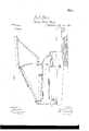
- FIG. 1 is a front view of my invention
- Fig. 2 a longitudinal vertical section of the same, taken in the line 00 m of Fig. 1
- Fig. 3 a horizontal section of a part of the same, taken in the line y y of Fig. 2
- Fig. 4 an enlarged detached side sectional View of a portion of the same; Fig.
- Fig. 5 an enlarged front view of a detached portion of the same;
- Fig. 6 a view of a portion of a hoop-skirt, showing the work performed by the machine;
- Fig. 7, a section of Fig. 6, taken in the line 2 z; and
- Fig. 8 an inverted perspective view of a clasp.
- the object of this invention is to obtain a machine by which the hoops of ladies hoopskirts may be rapidly clasped to the tapes thereof, and the work performed in a superior manner.
- the invention consists in the employment or use of a hopper and feeding-plate, the lat ter being peculiarlyconstructed and arranged and used in connection with a clinching mechanism, all being so arranged that the clasps, as the machine is operated, will be fed down in a proper manner to the clinching device, which is operated by the foot of the attendant and made to perform the desired work, the parts to be connected (the hoops and tapes) being presented to the machine by the hands of the attendant.
- A represents the stock or frame of the machine, which is composed of a horizontal arm, a, projecting from a short upright pillar, b, on a base-plate, 0. These parts may be of cast metal, and the pillarb and plate 0 may be cast in one pieee,while the arm a maybe cast separate and secured to the top of the pillar b by screws d.
- the pillar b has a slot or recess, 6, made in it, through which a lever, B, passes, the fulcrum-pin f of the lever passing through lugs or projections at the front part of the pillar.
- the back end of the lever B is connected by a rod or chain to a treadle, which may be arranged in the usual way.
- the base-plate c is bolted to a bench or framing of such a height as to admit of the attendant or operator sitting while at work with the machine.
- the rod D is a rod, which is fitted vertically in the back part of the arm a, and may be secured higher or lower in position by means of a setscrew, g.
- the upper part of the rod D is curved slightly forward, and has a horizontal bar, E, attached to it, which bar forms a support for the front end of a hopper, F, and the back end of a feeding-plate, G.
- the front end of the feeding-plate rests on the top of an upright head or bar, H, which is at the front end of the arm a, and may be cast with it in one piece.
- the back of the hopper F rests on the upper and horizontal pa1t of a rod, I, the lower part of which is inclined and is fitted in a slide, J on the rod D, said slide being secured on the rod at any desired point by a set-screw, h. (See Fig. 2.)
- a greater or less inclination may be given the hopper F, and the feeding-plate G may be more or less inclined by adjusting the rod D higher or lower in the arm a. This will be fully understood by referring to Fig. 2.
- the hopper F is simply a shallow sheetmetal box or pan of rectangular form open at its front end, and having a short vertical plate or ledge, co fitted obliquely at its front part and right-hand side, as shown in Fig. 1.
- the feeding-plate G has a more inclined position than the hopper F, and it may be described as being a plane with two bars, 1' j, attached nearly or about at right angles with each other. (See Fig; l.)
- the bars ij are not in contact, a space, it, being between them, and each bar has a groove, Z, made in the lower part of its face side, both of which are shown in Fig. 2.
- the bars 'Zj maybe termed conductors, as they conduct the clasps from the hopper F to the passage-way which leads them to the place where they are acted upon by the clinching device.
- This passage-way is formed of two vertical plates, on m, and a groove, '22, the plates being secured to the front side of the head or bar, H, with a small or narrow space, 0, between them, as shown in Fig. 1.
- the plates m an overlap the edges of the groove n, which is made vertically in the front of the head or bar 11. (See Fig. 3.)
- the feeding-plate G has an oblong slot or opening, 12, made through it at its front part, near the upper ends of the plates on m.
- This slot or opening is quite near the bar j, as will be seen by referring to Fig. 1, and it performs an important function, as will be presently explained.
- the lower ends of the vertical plates on m are curved so as to project underneath the front part of the head or bar H, as shown in Figs. 2 and 4.
- the plates I I represent two plates which are underneath the head or bar H, just back of the lower ends of the plates on m.
- the plates I I have each an upright flange, (1, at their back edges, and these flanges overlap each other and are secured to the head or bar II by a screw, r.
- the plates I I therefore, it will be seen, are suspended from the screw 0', the flanges q 1 being allowed to work freely 011 it.
- Each flange g has a small hook or pin, 3, attached, and around these pins a spring, 2, passes.
- This spring may be of india-rubber or other suitable elastic material, and it has a tendency to keep the inner edges of the plates I I in contact, in which position they are somewhat inclined, as shown in Figs. 1 and 5.
- a steel plate, J On the front end of the lever B, at its upper surface, there is secured a steel plate, J, which has an upright ledge, u, at each end. These ledges are each provided with a notch, 11. (See Figs. 3 and at.) At the center of the plate J there is also a small ledge or projection, w, which has a groove made longitudinally in its upper surface, said groove being of semicircular form in its transverse section, as shown in Fig. 4.
- the clasps K which are used with the machine, are of the ordinary construction, two
- prongs, a a projecting from a plate, 1), as
- the clasps pass down against the bar i in an inverted position, and are conducted by said bar to bar j, one side of the plates Z) of the clasps fitting in the grooves Z of the bars 1' said grooves Z serving to keep the clasps in proper position.
- the bar j conducts the clasps to the passage-Way formed by the plates m m and groove 41, and this passage-way maybe filled with clasps, the prongs a of which project through the spaoeo.
- the lowermost clasp, K has an upright position, as the lower curved ends of the plates m m conduct it between the plates I I, which retain it in such position directly over the ledge 10 of .the plate J, one of the plates I being notched at its inner edge to receive the clasp.
- the operator places the hoop M on the plate J, the loop Z) of the tape N being in the ledge w, and the back end of the lever B is drawn suddenly down by the action of the foot of the operator on the treadle, and the front end of the lever B is forced upward, and the prongs a, a of the clasps will be forced through the edges or sides of the loop I) and through the. tape N, and coming in contact with the concave or semicircular-grooved surface of the ledge 10 will be clinched at the under side of the tape N, as shown by the dotted lines in Fig. at.
- the hoop M is moved along on the plate J, and is secured to every tape'of the skirt in the way described.
- the clasps K feed themselves down in the passage-way behind the plates m m by their own gravity, and as the clasps K are clinched the plates I I are forced upward and apart by the action of the ledge to, (see dotted lines in Figs. 1 and 5,) so as to release the clinched clasp, the plates I I instantly closing under the action of the spring 15 as the plate J and ledge to descend.
- the bars j placed obliquely on the feeding-plate G, provided with grooves Z, and used in connection with the slot or opening 10, substantially as and for the purpose set forth.
Description
v 2 Shets-Sheet 1. B. A. MANN.
I Hoop Skirt Machine. I No. 34,026. Patented Dec. 24,1861.
Wwwa.
N. PETERS. Phuwmnn m har. Wuhinglon, D.C.
UNITED STATES PATENT OFFICE.
BELA A. MANN, OF WEST MERIDEN, CONNECTICUT, ASSIGNOR TO JEDEDIAH XVILCOX AND H. H. MILLER, OF SAME PLACE.
IMPROVEMENT IN MACHINES FOR CLASPING HOOPS TO LADIES SKIRTS.
Specification forming part of Let ters Patent No. 34,026, dated December 24, 1861.
T0 aZZ whom it may concern.-
Be it known that I, BELA A. MANN, of West Meriden, in the county of New Haven and State of Connecticut, have invented a new and useful Machine for Clasping Hoops to Ladies Skirts; and I do hereby declare that the following is a full, clear, and exact description of the same, reference being had to the annexed drawings, making a part of this specification, in which- Figure 1 is a front view of my invention; Fig. 2,a longitudinal vertical section of the same, taken in the line 00 m of Fig. 1; Fig. 3, a horizontal section of a part of the same, taken in the line y y of Fig. 2; Fig. 4:, an enlarged detached side sectional View of a portion of the same; Fig. 5, an enlarged front view of a detached portion of the same; Fig. 6, a view of a portion of a hoop-skirt, showing the work performed by the machine; Fig. 7, a section of Fig. 6, taken in the line 2 z; and Fig. 8 an inverted perspective view of a clasp.
Similar letters of reference indicate corresponding parts in the several figures.
The object of this invention is to obtain a machine by which the hoops of ladies hoopskirts may be rapidly clasped to the tapes thereof, and the work performed in a superior manner.
The invention consists in the employment or use of a hopper and feeding-plate, the lat ter being peculiarlyconstructed and arranged and used in connection with a clinching mechanism, all being so arranged that the clasps, as the machine is operated, will be fed down in a proper manner to the clinching device, which is operated by the foot of the attendant and made to perform the desired work, the parts to be connected (the hoops and tapes) being presented to the machine by the hands of the attendant.
To enable those skilled in the art to fully understand and construct my invention, I will proceed to describe it.
A represents the stock or frame of the machine, which is composed of a horizontal arm, a, projecting from a short upright pillar, b, on a base-plate, 0. These parts may be of cast metal, and the pillarb and plate 0 may be cast in one pieee,while the arm a maybe cast separate and secured to the top of the pillar b by screws d. The pillar b has a slot or recess, 6, made in it, through which a lever, B, passes, the fulcrum-pin f of the lever passing through lugs or projections at the front part of the pillar.
C is a spring, which is secured to the back part of the baseplate 0, and acts against the under side of the back part of lever B, and has a tendency to keep the front end of said lever in a downward position, as will be understood by referring to Fig. 2. The back end of the lever B is connected by a rod or chain to a treadle, which may be arranged in the usual way. The base-plate c is bolted to a bench or framing of such a height as to admit of the attendant or operator sitting while at work with the machine.
D is a rod, which is fitted vertically in the back part of the arm a, and may be secured higher or lower in position by means of a setscrew, g. The upper part of the rod D is curved slightly forward, and has a horizontal bar, E, attached to it, which bar forms a support for the front end of a hopper, F, and the back end of a feeding-plate, G. The front end of the feeding-plate rests on the top of an upright head or bar, H, which is at the front end of the arm a, and may be cast with it in one piece. The back of the hopper F rests on the upper and horizontal pa1t of a rod, I, the lower part of which is inclined and is fitted in a slide, J on the rod D, said slide being secured on the rod at any desired point by a set-screw, h. (See Fig. 2.) By adjusting the slide J higher or lower on the rod D a greater or less inclination may be given the hopper F, and the feeding-plate G may be more or less inclined by adjusting the rod D higher or lower in the arm a. This will be fully understood by referring to Fig. 2.
The hopper F is simply a shallow sheetmetal box or pan of rectangular form open at its front end, and having a short vertical plate or ledge, co fitted obliquely at its front part and right-hand side, as shown in Fig. 1.
The feeding-plate G has a more inclined position than the hopper F, and it may be described as being a plane with two bars, 1' j, attached nearly or about at right angles with each other. (See Fig; l.) The bars ij are not in contact, a space, it, being between them, and each bar has a groove, Z, made in the lower part of its face side, both of which are shown in Fig. 2. The bars 'Zj maybe termed conductors, as they conduct the clasps from the hopper F to the passage-way which leads them to the place where they are acted upon by the clinching device. This passage-way is formed of two vertical plates, on m, and a groove, '22, the plates being secured to the front side of the head or bar, H, with a small or narrow space, 0, between them, as shown in Fig. 1. The plates m an overlap the edges of the groove n, which is made vertically in the front of the head or bar 11. (See Fig. 3.)
The feeding-plate G has an oblong slot or opening, 12, made through it at its front part, near the upper ends of the plates on m. This slot or opening is quite near the bar j, as will be seen by referring to Fig. 1, and it performs an important function, as will be presently explained. The lower ends of the vertical plates on m are curved so as to project underneath the front part of the head or bar H, as shown in Figs. 2 and 4.
I I represent two plates which are underneath the head or bar H, just back of the lower ends of the plates on m. The plates I I have each an upright flange, (1, at their back edges, and these flanges overlap each other and are secured to the head or bar II by a screw, r. The plates I I therefore, it will be seen, are suspended from the screw 0', the flanges q 1 being allowed to work freely 011 it. Each flange g has a small hook or pin, 3, attached, and around these pins a spring, 2, passes. This spring may be of india-rubber or other suitable elastic material, and it has a tendency to keep the inner edges of the plates I I in contact, in which position they are somewhat inclined, as shown in Figs. 1 and 5.
On the front end of the lever B, at its upper surface, there is secured a steel plate, J, which has an upright ledge, u, at each end. These ledges are each provided with a notch, 11. (See Figs. 3 and at.) At the center of the plate J there is also a small ledge or projection, w, which has a groove made longitudinally in its upper surface, said groove being of semicircular form in its transverse section, as shown in Fig. 4.
The clasps K, which are used with the machine, are of the ordinary construction, two
prongs, a a, projecting from a plate, 1), as
motion. The clasps pass down against the bar i in an inverted position, and are conducted by said bar to bar j, one side of the plates Z) of the clasps fitting in the grooves Z of the bars 1' said grooves Z serving to keep the clasps in proper position. The bar j conducts the clasps to the passage-Way formed by the plates m m and groove 41, and this passage-way maybe filled with clasps, the prongs a of which project through the spaoeo. The lowermost clasp, K, has an upright position, as the lower curved ends of the plates m m conduct it between the plates I I, which retain it in such position directly over the ledge 10 of .the plate J, one of the plates I being notched at its inner edge to receive the clasp. In case a clasp should not be in proper position against the bar j, it cannot pass the slot or opening 1), as the latter is so close to j that a clasp in an improper position would fall through said slot into box L. The clasps, when in proper position, are retained against the bar, in consequence of the end of the plates 1) being in the groove Z, and when this is not the case the clasps must fall through the slot or opening. The operator places the hoop M on the plate J, the loop Z) of the tape N being in the ledge w, and the back end of the lever B is drawn suddenly down by the action of the foot of the operator on the treadle, and the front end of the lever B is forced upward, and the prongs a, a of the clasps will be forced through the edges or sides of the loop I) and through the. tape N, and coming in contact with the concave or semicircular-grooved surface of the ledge 10 will be clinched at the under side of the tape N, as shown by the dotted lines in Fig. at. The hoop M is moved along on the plate J, and is secured to every tape'of the skirt in the way described. The clasps K feed themselves down in the passage-way behind the plates m m by their own gravity, and as the clasps K are clinched the plates I I are forced upward and apart by the action of the ledge to, (see dotted lines in Figs. 1 and 5,) so as to release the clinched clasp, the plates I I instantly closing under the action of the spring 15 as the plate J and ledge to descend.
Having thus described my invention, what I claim as new, and desire to secure by Letters Patent, is
1. The inclined hopper F and feeding-plate G, when arranged so as to be adjusted by the rods D I, and used in connection with a clinching device, for the purpose herein set forth.
2. The bars j, placed obliquely on the feeding-plate G, provided with grooves Z, and used in connection with the slot or opening 10, substantially as and for the purpose set forth.
3. The passage-way for the clasps K, formed of the plates m 0%, attached to the head or bar H, and groove 01, made therein, when said passage-way is used in combination with the feeding-plate G and the clinching device and arranged therewith, as and for the purpose specified.
L. The clinching device formed of the plate J, attached to lever B or its equivalent and provided With the ledge w, having a concave or grooved upper surface, in combination with the clasp-sustaining plates I I, attached to the head or barrel H, and arranged in relation with the plates m m and groove n, substantially as and for the purpose herein set forth.
BELA A. MANN. Witnesses:
GEORGE W. SMITH, GEORGE W. ROGERS.
Publications (1)
| Publication Number | Publication Date |
|---|---|
| US34026A true US34026A (en) | 1861-12-24 |
Family
ID=2103612
Family Applications (1)
| Application Number | Title | Priority Date | Filing Date |
|---|---|---|---|
| US34026D Expired - Lifetime US34026A (en) | Improvement in machines for clasping hoops to ladies skirts |
Country Status (1)
| Country | Link |
|---|---|
| US (1) | US34026A (en) |
Cited By (2)
| Publication number | Priority date | Publication date | Assignee | Title |
|---|---|---|---|---|
| US5783949A (en) * | 1994-07-22 | 1998-07-21 | International Business Machines Corporation | Precharged bit decoder and sense amplifier with integrated latch usable in pipelined memories |
| US6144230A (en) * | 1998-05-25 | 2000-11-07 | Hyundai Electronics Industries Co., Ltd. | Sense amplifier driving device |
-
0
- US US34026D patent/US34026A/en not_active Expired - Lifetime
Cited By (2)
| Publication number | Priority date | Publication date | Assignee | Title |
|---|---|---|---|---|
| US5783949A (en) * | 1994-07-22 | 1998-07-21 | International Business Machines Corporation | Precharged bit decoder and sense amplifier with integrated latch usable in pipelined memories |
| US6144230A (en) * | 1998-05-25 | 2000-11-07 | Hyundai Electronics Industries Co., Ltd. | Sense amplifier driving device |
Similar Documents
| Publication | Publication Date | Title |
|---|---|---|
| US34026A (en) | Improvement in machines for clasping hoops to ladies skirts | |
| USRE1518E (en) | Improvement in machines for clasping hoops to ladies skirts | |
| US37124A (en) | Improvement in apparatus for | |
| US10285A (en) | Sutportistgr falling table-leaves | |
| US309080A (en) | mosher | |
| US28108A (en) | Machine fob finishing leather | |
| US49109A (en) | Improvement in wood-bending machines | |
| US6817A (en) | Circular-saw set | |
| US136595A (en) | Improvement in mechanisms for heading barrels | |
| US95800A (en) | Improvement in machine for wiring blind-rods | |
| US50728A (en) | Improvement in apparatus for clasping hoop-skirts | |
| US373307A (en) | Machine for setting laci ng-hooks | |
| US79810A (en) | Albert carter | |
| US1281403A (en) | Animal-trap. | |
| US161650A (en) | Improvement in box-nailing machines | |
| US496981A (en) | Feeding-chamber and door for baling-presses | |
| US544528A (en) | Button-attaching machine | |
| US123139A (en) | Improvement in machines for stuffing horse-collars | |
| US663058A (en) | Cattle-stanchion. | |
| US284911A (en) | Machine | |
| US394546A (en) | Button-setting machine | |
| US233606A (en) | Machine for making hog-rings | |
| US310541A (en) | Button-fasten e resetting machine | |
| US18080A (en) | Machine eob wiring blind-bods | |
| US394217A (en) | Machine for making staples |