US3336870A - Remotely controlled flare firing device and method - Google Patents
Remotely controlled flare firing device and method Download PDFInfo
- Publication number
- US3336870A US3336870A US488293A US48829365A US3336870A US 3336870 A US3336870 A US 3336870A US 488293 A US488293 A US 488293A US 48829365 A US48829365 A US 48829365A US 3336870 A US3336870 A US 3336870A
- Authority
- US
- United States
- Prior art keywords
- flares
- flare
- firing
- pin
- plate
- Prior art date
- Legal status (The legal status is an assumption and is not a legal conclusion. Google has not performed a legal analysis and makes no representation as to the accuracy of the status listed.)
- Expired - Lifetime
Links
- 238000010304 firing Methods 0.000 title description 30
- 238000000034 method Methods 0.000 title description 11
- 230000000452 restraining effect Effects 0.000 claims description 7
- 230000033001 locomotion Effects 0.000 claims description 4
- 238000009527 percussion Methods 0.000 claims description 3
- 230000000903 blocking effect Effects 0.000 claims description 2
- 238000011084 recovery Methods 0.000 description 12
- 230000007246 mechanism Effects 0.000 description 5
- 230000000712 assembly Effects 0.000 description 4
- 238000000429 assembly Methods 0.000 description 4
- 230000004913 activation Effects 0.000 description 2
- 238000001994 activation Methods 0.000 description 2
- 239000000779 smoke Substances 0.000 description 2
- XLYOFNOQVPJJNP-UHFFFAOYSA-N water Substances O XLYOFNOQVPJJNP-UHFFFAOYSA-N 0.000 description 2
- 241001352457 Calitys Species 0.000 description 1
- 235000015842 Hesperis Nutrition 0.000 description 1
- 235000012633 Iberis amara Nutrition 0.000 description 1
- 230000009471 action Effects 0.000 description 1
- 239000000956 alloy Substances 0.000 description 1
- 229910045601 alloy Inorganic materials 0.000 description 1
- 239000002775 capsule Substances 0.000 description 1
- 239000000919 ceramic Substances 0.000 description 1
- 230000000881 depressing effect Effects 0.000 description 1
- 230000007613 environmental effect Effects 0.000 description 1
- 238000005286 illumination Methods 0.000 description 1
- 239000000463 material Substances 0.000 description 1
- 239000002184 metal Substances 0.000 description 1
- 229910052751 metal Inorganic materials 0.000 description 1
- 150000002739 metals Chemical class 0.000 description 1
- 238000012986 modification Methods 0.000 description 1
- 230000004048 modification Effects 0.000 description 1
- 230000002093 peripheral effect Effects 0.000 description 1
- 229920003023 plastic Polymers 0.000 description 1
- 239000004033 plastic Substances 0.000 description 1
- 230000001681 protective effect Effects 0.000 description 1
- 238000009877 rendering Methods 0.000 description 1
- 230000004044 response Effects 0.000 description 1
- 239000013535 sea water Substances 0.000 description 1
- 230000035939 shock Effects 0.000 description 1
Images

Classifications
-
- F—MECHANICAL ENGINEERING; LIGHTING; HEATING; WEAPONS; BLASTING
- F41—WEAPONS
- F41A—FUNCTIONAL FEATURES OR DETAILS COMMON TO BOTH SMALLARMS AND ORDNANCE, e.g. CANNONS; MOUNTINGS FOR SMALLARMS OR ORDNANCE
- F41A19/00—Firing or trigger mechanisms; Cocking mechanisms
- F41A19/58—Electric firing mechanisms
- F41A19/59—Electromechanical firing mechanisms, i.e. the mechanical striker element being propelled or released by electric means
-
- F—MECHANICAL ENGINEERING; LIGHTING; HEATING; WEAPONS; BLASTING
- F41—WEAPONS
- F41A—FUNCTIONAL FEATURES OR DETAILS COMMON TO BOTH SMALLARMS AND ORDNANCE, e.g. CANNONS; MOUNTINGS FOR SMALLARMS OR ORDNANCE
- F41A19/00—Firing or trigger mechanisms; Cocking mechanisms
- F41A19/06—Mechanical firing mechanisms, e.g. counterrecoil firing, recoil actuated firing mechanisms
- F41A19/18—Mechanical firing mechanisms, e.g. counterrecoil firing, recoil actuated firing mechanisms for multibarrel guns or multiple guns
- F41A19/19—Mechanical firing mechanisms, e.g. counterrecoil firing, recoil actuated firing mechanisms for multibarrel guns or multiple guns with single-trigger firing possibility
- F41A19/21—Mechanical firing mechanisms, e.g. counterrecoil firing, recoil actuated firing mechanisms for multibarrel guns or multiple guns with single-trigger firing possibility having only one trigger
-
- F—MECHANICAL ENGINEERING; LIGHTING; HEATING; WEAPONS; BLASTING
- F42—AMMUNITION; BLASTING
- F42B—EXPLOSIVE CHARGES, e.g. FOR BLASTING, FIREWORKS, AMMUNITION
- F42B4/00—Fireworks, i.e. pyrotechnic devices for amusement, display, illumination or signal purposes
- F42B4/22—Fireworks, i.e. pyrotechnic devices for amusement, display, illumination or signal purposes characterised by having means to separate article or charge from casing without destroying the casing
Definitions
- ABSTRACT OF THE DISCLOSURE Apparatus for firing in sequence a plurality of flares or other pyrotechnic devices A plurality of flares are arranged circumferentially within a tubular housing, each flare being contained within a barrel which also includes a spring-loaded firing pin. All the pins are restrained from movement toward their associated flares by a rotatable plate having a single slot formed therein. When the plate is rotated, this slot is brought into successive alignment with different ones of the firing pins to permit the particular pin then in alignment with the slot to be propelled by its spring toward its associated flare to fire the latter. Sequential firing of all the flares results from continued rotation of the plate.
- the present invention relates generally to flare launching means and more particularly to a method and means for containing a plurality of flares or other pyrotechnic devices each of which may be fired singly upon command from a remote station.
- flare devices are generally single shot in nature making it very difiicult for targets to be located within the time the flare will remain burning. Also, the available flare devices are usually released on the occurrence of an impact or a preselected temperature or other condition rendering it necessary that the recovery personnel be within viewing distance of the object at the time the flare is fired.
- a flare releasing method and mechanism which will store flares at the cality where an emergency may develop or store flares in a vehicle which is desired to be recovered and whose exact trajectory and landing place may not be readily or closely enough ascertained so as to permit rapid recovery by planned recovery procedures.
- Another situation where conventional flare devices are unsatisfactory is in the case of personnel downed at sea or on land remote from conventional rescue teams. In such cases where these personnel are incapacitated and therefore unable to launch flares a device which will fire the flares upon command emanating from a search vehicle is quite essential in order to quickly ascertain the location of the downed personnel.
- the present invention overcomes the disadvantages and shortcomings of prior flare launching methods and devices and provides a magazine containing several flares which may be fired at any desired time to assist in location of the site.
- the flares may be fired by radio or electrical signal which actuates a solenoid to successively fire flares from a flare magazine.
- a further object is to provide a flare launch method and mechanism having a quantity of flares arranged for sequential firing on remote command, which may be mounted in a missile or rocket and will satisfactorily withstand the shock of rocket launch and landing.
- a still further object is to provide a flare storage and remote firing mechanism which will withstand drop by parachute and thereafter serve to identify and illuminate an area to which rescue teams may be directed.
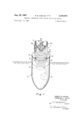
- FIG. 1 is a schematic view of a device embodying the present invention employed to assist in the recovery at sea of a missile nose cone;
- FIG. 2 is a vertical sectional view, partly in elevation, of the embodiment illustrated in FIG. 1 (for simplicity background details are omitted);
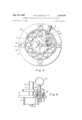
- FIG. 3 is a top plan view of the embodiment shown in FIG. 2;
- FIG. 4 is a side elevation somewhat enlarged and partially broken away of a safety locking device.
- the present invention is shown attached to one end of a nose cone 10 of a missile floating nose down in a body of water with the flare storage and firing device 11 attached to the exposed connecting interface 12 of the nose cone and oriented to direct the flares upwardly.
- the device includes spaced upper and lower plates 14 and 15 which are interconnected by a tubular collar 13 and support a plurality of peripherally located barrels 16 each of which carries a flare or other pyrotechnic device 17.
- the flares are fired through operation of a rotary solenoid 18 which may be battery operated and may be remotely controlled through a radio command link including a receiver 19.
- a circumferential shield 20 provides protection for the flares.
- this embodiment of the device is shown attached to a buoyant nose cone it may readily be appreciated that the carrying vehicle may be a target plane, a test device or other suitable object and the flight may have terminated on land rather than on water.
- the upper and lower plates 14 and 15 are held in spaced relationship by collar 13 while a second collar 24 suspends solenoid 18 below plate 15.
- Barrels 16 are received in aligned peripheral openings in plates 14 and 15 and are secured therein by set screws 25 in plate 15.
- Each barrel is internally threaded at the lower end to receive a plug 27 and at the upper end to receive a flare or other pyrotechnic device 17.
- Shaft 30 extends upwardly from the rotary solenoid 18 and is journaled in roller bearings 31 and 32 provided in plate 15 and 14.
- the upper end of shaft 30 immediately above plate 14 carries an extension forming a rotor assembly generally indicated at 35 which includes an enlarged hollow tube 36 having a radially extending firing pin restraining plate 37 around its lower portion. This rotor assembly is secured to the upper end of shaft 30 by a cross pin 40.
- upper support plate 14 carries protective shield 20 which may be affixed to plate 14 by such means as bolts and nuts 42 which hold lugs 43 of the shield to plate 14.
- Plate 14 and rotatable plate 37 are spaced from one another along the vertical axis 44 of the device. with the rim of plate 37 notched at 46.
- a stop block 47 is shown aflixed to upper plate 14 by recessed bolts 48, and a passage 49 therethrough accommodates a ball lock safety pin 50 shown in detail in FIG. 4.
- Housing 51 is attached to plate 14 and received in collar 13 to accommodate the lower end of pin 50.
- Each barrel 16 is provided with an elongated slot 52 through which projects a threaded screw 53 of the respective firing pin release assembly 54. In the ready position for launching flares, firing pin assemblies 54 are all retracted but are urged against the under surface of plate 37 by the upward force of firing pin springs 57 which force is exerted against the base of firing pins 58.
- Ball lock safety pin 50 may have a ring 60 connected thereto to which a lanyard may be attached for effecting removal of the ball lock pin when flare device is readied for service. Ball lock pin 50 prevents rotation of plate 37 until such time as it is desired to prepare the device for operation.
- Firing pin release assembly 54 is shown in detail in FIG. 2 and includes a roller bearing 62 mounted on screw 53 so that the roller bears against and rolls along the undersurface of restraining plate 37.
- slot 46 registers with each roller assembly it permits movement upward of release assembly 54 and the associated firing pin to fire the flare aflixed to that barrel.
- the release assemblies 54 are shown positioned under plate 37 at points around the periphery thereof such that stepwise rotation brings slot 46 into successive registry with successive assemblies thereby permitting each assembly to move upwardly under the urging of its spring 57.
- Tubular extension 36 may be manually rotated by gripping the upturned protruding ends of a second cross pin 64 and may be provided with a short collar as shown at 65 to receive a cover-securing ball lock pin 67 which pin may also be used to secure cover 68 against the side of shield 20 when the device is readied for use.
- flare launcher 10 is attached to an ob- 'ject which is to be recovered, or is prepared for use in marking a site or area, and cover 68 is secured to shield 20 preferably as shown in FIG. 2.
- Each of barrels 16 is armed for operation by depressing its respective firing pin 58 and thereafter rotating restraining plate 37. Springs 57 are thereby compressed until all release assemblies 54 bear against the under surface of plate 37.
- the safety or arming pin 50 is now inserted to provide a positive lock against rotation of plate 37. In this condition all barrels are ready and flares 17 now may be aflixed to the top of each barrel.
- Solenoid 18 may be activated by a locally generated electric current or remotely by radio control acting through suitable batteries. Such activation causes rotary solenoid 18 to rotate one step or 30 thereby freeing the firing pin restraining assembly 54 for the first barrel. Successive activations release succeeding barrels in sequence.
- the device is shown adapted to be employed in missile nose cone recovery operations, however, in launching the device from an aircraft a lanyard attached to ring 60 could be so secured that upon the device falling away from the plane arming pin 50 would be withdrawn freeing plate 37 for rotation. Upon recovery of the device the cover 68 should be secured over the open top of shield 20.
- the device may be mounted on any type of vehicle and used to fire flares, smoke generation pyrotechnics, or any other type of signal means which can be initiated by percussion. Since the device is primarily powered by springs, it requires only a relatively small amount of electrical power. Although the embodiment described was devised to fire flares to assist in recovering capsules from the ocean, it will be appreciated that its ruggedness and safety features make it applicable for launching from other objects as when parachuted to remote areas where illumination by flare is desired.
- the quick release ball lock pin attached to the lanyard provides for automatic arming of the device upon being dropped or otherwise launched from a plane or other vehicle.
- the safety recovery feature, cover 68 provides protection for personnel who .are retrieving the device or persons who handle the vehicle containing the device upon recovery against an unused flare being fired by accident.
- the present invention will fire a rocket flare several hundred feet into the air, being visible as far away as 30 or more miles.
- the flares may be fired at any interval of time by recovery personnel aboard searching aircraft.
- eleven barrels and flares in the present embodiment is not intended to be limitative, it being appreciated that more or fewer flares may be contained and also that the flares may be contained in more than one circular ring about the rotor.
- the flares used in the present device may carry a greater charge than those usable in conventional flare mechanisms resulting in a much greater altitude and range of visibility.
- the device may be constructed of several types of material such as plastics, ceramics or metals or alloys as desired according to environmental requirements.
- a spring motor may be used to replace the solenoid if desired.
- a device for firing a plurality of pyrotechnic devices in sequence comprising:
Landscapes
- Engineering & Computer Science (AREA)
- General Engineering & Computer Science (AREA)
- Aiming, Guidance, Guns With A Light Source, Armor, Camouflage, And Targets (AREA)
Description
Aug. 22, 1967 R. B GUNYAN ET AL v REMOTELY CONTROLLED FLARE FIRING DEVICE AND METHOD Filed Sept. 1'7, 1965 3 Sheets-Sheet 1 ROBERT B. GUNYAN CRAWFORD L. SACHS I N V {E O S ("5 {f AGE/V7 a;@@ Q ATTORNEY REMOTELY CONTROLLED FLARE FiRING DEVICE AND METHOD Filed Sept. 17, 1965 42 43 l l 54 I g i ph I V I4 y 58 I 3g I I I I6 2'5 X Z a I 1" I l l' s Sheets-$heet 2 7 Aug. 22, 1967 R. B. GUNYAN ET AL 3,336,870
REMOTELY CONTROLLED FLARE FIRING DEVICE AND METHOD Filed Sept. 17, 1965 3 Sheets-Sheet 5 Fig.3
United States Patent 3,336,870 REMOTELY CONTROLLED FLARE FIRING DEVICE AND METHOD Robert B. Gunyan and Crawford L. Sachs, Oxnard, Califi, assignors to the United States of America as represented by the Secretary of the Navy Filed Sept. 17, 1965, Ser. No. 488,293 3 Claims. (Cl. 10237.6)
ABSTRACT OF THE DISCLOSURE Apparatus for firing in sequence a plurality of flares or other pyrotechnic devices. A plurality of flares are arranged circumferentially within a tubular housing, each flare being contained within a barrel which also includes a spring-loaded firing pin. All the pins are restrained from movement toward their associated flares by a rotatable plate having a single slot formed therein. When the plate is rotated, this slot is brought into successive alignment with different ones of the firing pins to permit the particular pin then in alignment with the slot to be propelled by its spring toward its associated flare to fire the latter. Sequential firing of all the flares results from continued rotation of the plate.
The invention described herein may be manufactured and used by or for the Government of the United States of America for governmental purposes without the payment of any royalties thereon or therefor.
The present invention relates generally to flare launching means and more particularly to a method and means for containing a plurality of flares or other pyrotechnic devices each of which may be fired singly upon command from a remote station.
Recovery of personnel, missiles, rockets and other objects from either the sea or lakes or from remote land areas is often a costly and lengthy procedure due to lack of an adequate marking or location designating device such as a flare or-radiosignal. Recovery at sea is even more diflicult due to the vast areas to be viewed or scanned and to the relatively minute size of objects which may float and therefore be susceptible of recovery.
Conventional flare devices are generally single shot in nature making it very difiicult for targets to be located within the time the flare will remain burning. Also, the available flare devices are usually released on the occurrence of an impact or a preselected temperature or other condition rendering it necessary that the recovery personnel be within viewing distance of the object at the time the flare is fired. There is thus a need for a flare releasing method and mechanism which will store flares at the cality where an emergency may develop or store flares in a vehicle which is desired to be recovered and whose exact trajectory and landing place may not be readily or closely enough ascertained so as to permit rapid recovery by planned recovery procedures. Another situation where conventional flare devices are unsatisfactory is in the case of personnel downed at sea or on land remote from conventional rescue teams. In such cases where these personnel are incapacitated and therefore unable to launch flares a device which will fire the flares upon command emanating from a search vehicle is quite essential in order to quickly ascertain the location of the downed personnel.
The present invention overcomes the disadvantages and shortcomings of prior flare launching methods and devices and provides a magazine containing several flares which may be fired at any desired time to assist in location of the site. The flares may be fired by radio or electrical signal which actuates a solenoid to successively fire flares from a flare magazine.
Accordingly, it is an object of the present invention to provide a flare storage and firing mechanism which is operable by remote command.
It is another object of the invention to provide a flare magazine or housing containing a plurality of flares which may be individually launched as desired over a period of time.
A further object is to provide a flare launch method and mechanism having a quantity of flares arranged for sequential firing on remote command, which may be mounted in a missile or rocket and will satisfactorily withstand the shock of rocket launch and landing.
A still further object is to provide a flare storage and remote firing mechanism which will withstand drop by parachute and thereafter serve to identify and illuminate an area to which rescue teams may be directed.
It is a further object of the present invention to provide a rugged flare storage and firing device which is simple in operation and yet provides for selective discharge of flares by either local or remote control.
Other objects and many of the attendant advantages of this invention will be readily appreciated as the same becomes better understood by reference to the following detailed description when considered in connection with the accompanying drawings in which like numerals designate like parts throughout and wherein:
FIG. 1 is a schematic view of a device embodying the present invention employed to assist in the recovery at sea of a missile nose cone;
FIG. 2 is a vertical sectional view, partly in elevation, of the embodiment illustrated in FIG. 1 (for simplicity background details are omitted);
FIG. 3 is a top plan view of the embodiment shown in FIG. 2; and
'FIG. 4 is a side elevation somewhat enlarged and partially broken away of a safety locking device.
Referring now to FIG. 1, the present invention is shown attached to one end of a nose cone 10 of a missile floating nose down in a body of water with the flare storage and firing device 11 attached to the exposed connecting interface 12 of the nose cone and oriented to direct the flares upwardly. As shown in FIGS. 2 and 3 the device includes spaced upper and lower plates 14 and 15 which are interconnected by a tubular collar 13 and support a plurality of peripherally located barrels 16 each of which carries a flare or other pyrotechnic device 17. The flares are fired through operation of a rotary solenoid 18 which may be battery operated and may be remotely controlled through a radio command link including a receiver 19. A circumferential shield 20 provides protection for the flares. Although this embodiment of the device is shown attached to a buoyant nose cone it may readily be appreciated that the carrying vehicle may be a target plane, a test device or other suitable object and the flight may have terminated on land rather than on water.
The upper and lower plates 14 and 15 are held in spaced relationship by collar 13 while a second collar 24 suspends solenoid 18 below plate 15. Barrels 16 are received in aligned peripheral openings in plates 14 and 15 and are secured therein by set screws 25 in plate 15. Each barrel is internally threaded at the lower end to receive a plug 27 and at the upper end to receive a flare or other pyrotechnic device 17. Shaft 30 extends upwardly from the rotary solenoid 18 and is journaled in roller bearings 31 and 32 provided in plate 15 and 14. The upper end of shaft 30 immediately above plate 14 carries an extension forming a rotor assembly generally indicated at 35 which includes an enlarged hollow tube 36 having a radially extending firing pin restraining plate 37 around its lower portion. This rotor assembly is secured to the upper end of shaft 30 by a cross pin 40.
As best shown in FIGS. 1 and 2, upper support plate 14 carries protective shield 20 which may be affixed to plate 14 by such means as bolts and nuts 42 which hold lugs 43 of the shield to plate 14. Plate 14 and rotatable plate 37 are spaced from one another along the vertical axis 44 of the device. with the rim of plate 37 notched at 46. A stop block 47 is shown aflixed to upper plate 14 by recessed bolts 48, and a passage 49 therethrough accommodates a ball lock safety pin 50 shown in detail in FIG. 4. Housing 51 is attached to plate 14 and received in collar 13 to accommodate the lower end of pin 50. Each barrel 16 is provided with an elongated slot 52 through which projects a threaded screw 53 of the respective firing pin release assembly 54. In the ready position for launching flares, firing pin assemblies 54 are all retracted but are urged against the under surface of plate 37 by the upward force of firing pin springs 57 which force is exerted against the base of firing pins 58.
Ball lock safety pin 50 may have a ring 60 connected thereto to which a lanyard may be attached for effecting removal of the ball lock pin when flare device is readied for service. Ball lock pin 50 prevents rotation of plate 37 until such time as it is desired to prepare the device for operation.
Firing pin release assembly 54 is shown in detail in FIG. 2 and includes a roller bearing 62 mounted on screw 53 so that the roller bears against and rolls along the undersurface of restraining plate 37. When slot 46 registers with each roller assembly it permits movement upward of release assembly 54 and the associated firing pin to fire the flare aflixed to that barrel.
In FIG. 3, the release assemblies 54 are shown positioned under plate 37 at points around the periphery thereof such that stepwise rotation brings slot 46 into successive registry with successive assemblies thereby permitting each assembly to move upwardly under the urging of its spring 57. Tubular extension 36 may be manually rotated by gripping the upturned protruding ends of a second cross pin 64 and may be provided with a short collar as shown at 65 to receive a cover-securing ball lock pin 67 which pin may also be used to secure cover 68 against the side of shield 20 when the device is readied for use.
In operation, flare launcher 10 is attached to an ob- 'ject which is to be recovered, or is prepared for use in marking a site or area, and cover 68 is secured to shield 20 preferably as shown in FIG. 2. Each of barrels 16 is armed for operation by depressing its respective firing pin 58 and thereafter rotating restraining plate 37. Springs 57 are thereby compressed until all release assemblies 54 bear against the under surface of plate 37. The safety or arming pin 50 is now inserted to provide a positive lock against rotation of plate 37. In this condition all barrels are ready and flares 17 now may be aflixed to the top of each barrel.
In the embodiment shown eleven barrels are spaced 30 around the periphery of the device, the remaining 30-degrees sector being reserved for the safety or arming pin assembly shown in FIG. 4. With the flares installed and the cover mounted at the side of the shield the device is ready for operation upon removal of the arming pin 50. Solenoid 18 may be activated by a locally generated electric current or remotely by radio control acting through suitable batteries. Such activation causes rotary solenoid 18 to rotate one step or 30 thereby freeing the firing pin restraining assembly 54 for the first barrel. Successive activations release succeeding barrels in sequence.
The device is shown adapted to be employed in missile nose cone recovery operations, however, in launching the device from an aircraft a lanyard attached to ring 60 could be so secured that upon the device falling away from the plane arming pin 50 would be withdrawn freeing plate 37 for rotation. Upon recovery of the device the cover 68 should be secured over the open top of shield 20.
The device may be mounted on any type of vehicle and used to fire flares, smoke generation pyrotechnics, or any other type of signal means which can be initiated by percussion. Since the device is primarily powered by springs, it requires only a relatively small amount of electrical power. Although the embodiment described was devised to fire flares to assist in recovering capsules from the ocean, it will be appreciated that its ruggedness and safety features make it applicable for launching from other objects as when parachuted to remote areas where illumination by flare is desired. The quick release ball lock pin attached to the lanyard provides for automatic arming of the device upon being dropped or otherwise launched from a plane or other vehicle. The safety recovery feature, cover 68, provides protection for personnel who .are retrieving the device or persons who handle the vehicle containing the device upon recovery against an unused flare being fired by accident.
The present invention will fire a rocket flare several hundred feet into the air, being visible as far away as 30 or more miles. When operated by radio command, the flares may be fired at any interval of time by recovery personnel aboard searching aircraft. The use of eleven barrels and flares in the present embodiment is not intended to be limitative, it being appreciated that more or fewer flares may be contained and also that the flares may be contained in more than one circular ring about the rotor.
There are distinct advantages of the present device over such conventional area identification means such as dye markers, smoke generators actuated upon contact with sea water, or electrically ignited squibs which require much more power and therefore are limited in the number of flares that may be carried as well as in the efficiency of firing these flares. The flares used in the present device may carry a greater charge than those usable in conventional flare mechanisms resulting in a much greater altitude and range of visibility.
The device may be constructed of several types of material such as plastics, ceramics or metals or alloys as desired according to environmental requirements. A spring motor may be used to replace the solenoid if desired. It will be recognized that many modifications and variations of the present invention are possible in the light of the above teachings. It is therefore to be understood that within the scope of the appended claims the invention may be practiced otherwise than as specifically described.
We claim:
1. A device for firing a plurality of pyrotechnic devices in sequence comprising:
a housing having a pyrotechnic discharge opening;
a plurality of pyrotechnic devices within said housing and directed out said opening;
a percussion firing pin associated with each pyrotechnic device;
means normally urging said pin toward the pyrotechnic device;
restraining means normally blocking movement of each firing pin; and
means for actuating the restraining means to release successive pins in response to a signal from a remote point.
2. In a device for sequentially firing a plurality of flares, the combination of:
an essentially tubular housing;
a plurality of flare barrels spaced-apart circumferentially within said housing and disposed parallel to the axis thereof;
a plurality of flares respectively carried in said barrels;
a plurality of flare-firing pins respectively carried in said barrels out of contact with said flares;
5 6 a plurality of spring elements additionally carried in sequential release of said pins and hence a sequential said barrels and respectively contacting said pins to firing of said fires. urge the latter toward contact With their respective 3. The combination of claim 2, further comprising flares; a locking pin manually insertable through the slot in arestraining plate of circular outline rotatably mounted 5 Said plate and acting to preclude rotation of the latter within said housing and having an axis f rotation until said device is armed by withdrawal of said locking coinciding with the axis of said tubular housing, P said plate being in contact with said pins and re References Clted straining the latter from being urged into contact UNITED STATES PATENTS with their respective flares as a result of the action 10 1,937,220 11/1933 Driggs 5 Of sald Spring elements; 2,473,050 6/1949 Camp z44 1 X said plate having a slot formed therein on the periphery 2 561,421 7/1951 S l et 1 thereof, said slot being sequentially alignable with 2,639,106 5/1953 Sesera 2441 successive barrels of said plurality upon rotation 15 2,876,678 3/1959 Lyon 89-1.804 of said plate so as to release one .pin of said plurality 2,971,731 2/ 1961 GraW 89-1.5 X from restraint and permit said one pin to be forced 3,102,477 9/ 1963 Stefan t a 1O237-r6 1,1"g,f,jggifi fgg gfj g ijgfigi if? by the BENJAMIN A. BORCHELT, Primary Examiner.
means for rotating said plate so as to bring about a 20 ROBERT F. STAHL, Examiner.
Claims (1)
1. A DEVICE FOR FIRING A PLURALITY OF PYROTECHNIC DEVICES IN SEQUENCE COMPRISING: A HOUSING HAVING A PYROTECHNIC DISCHARGE OPENING; A PLURALITY OF PYROTECHNIC DEVICES WITHIN SAID HOUSING AND DIRECTED OUT SAID OPENING; A PERCUSSION FIRING PIN ASSOCIATED WITH EACH PYROTECHNIC DEVICE; MEANS NORMALLYH URGING SAID PIN TOWARD THE PYROTECHNIC DEVICE; RESTRAINING MEANS NORMALLY BLOCKING MOVEMENT OF EACH FIRING PIN; AND
Priority Applications (1)
| Application Number | Priority Date | Filing Date | Title |
|---|---|---|---|
| US488293A US3336870A (en) | 1965-09-17 | 1965-09-17 | Remotely controlled flare firing device and method |
Applications Claiming Priority (1)
| Application Number | Priority Date | Filing Date | Title |
|---|---|---|---|
| US488293A US3336870A (en) | 1965-09-17 | 1965-09-17 | Remotely controlled flare firing device and method |
Publications (1)
| Publication Number | Publication Date |
|---|---|
| US3336870A true US3336870A (en) | 1967-08-22 |
Family
ID=23939137
Family Applications (1)
| Application Number | Title | Priority Date | Filing Date |
|---|---|---|---|
| US488293A Expired - Lifetime US3336870A (en) | 1965-09-17 | 1965-09-17 | Remotely controlled flare firing device and method |
Country Status (1)
| Country | Link |
|---|---|
| US (1) | US3336870A (en) |
Cited By (13)
| Publication number | Priority date | Publication date | Assignee | Title |
|---|---|---|---|---|
| US3535809A (en) * | 1967-11-03 | 1970-10-27 | Hoffmann Werke Oswald | Firing equipment for simulating gunfire |
| US3628416A (en) * | 1969-10-15 | 1971-12-21 | George L Kernan | Flare-dispensing and igniting apparatus |
| US4154168A (en) * | 1978-02-13 | 1979-05-15 | The United States Of America As Represented By The Secretary Of The Navy | Flare release system |
| US6318350B1 (en) * | 1999-08-05 | 2001-11-20 | Innotek, Inc. | Remote controlled mock bird launcher |
| US6502343B2 (en) * | 2001-03-30 | 2003-01-07 | Joung Young Cheng | Emergency rescue device |
| WO2005106379A1 (en) * | 2004-05-04 | 2005-11-10 | Giuseppe Centrone | Launch apparatus |
| US20060201372A1 (en) * | 2005-03-08 | 2006-09-14 | Eugen Nicolae | Flare distributor |
| US20070240350A1 (en) * | 2006-04-12 | 2007-10-18 | The Johns Hopkins University | Automatic Integrated Distress Device |
| US20080000377A1 (en) * | 2006-06-30 | 2008-01-03 | Thomas Doyle | Simulating An Explosion Of An Improvised Explosive Device |
| US7568431B1 (en) * | 2003-01-13 | 2009-08-04 | Pacific Coast Systems | Multi-purpose pyrotechnic trainer |
| US8011928B1 (en) | 2007-11-27 | 2011-09-06 | Pacific Coast Systems | Mine-like explosion simulator |
| USD672006S1 (en) | 2011-01-11 | 2012-12-04 | Pacific Coast Systems | Casing for a pyrotechnic training unit |
| US8479651B2 (en) | 2011-01-11 | 2013-07-09 | Pacific Coast Systems | Pyrotechnic training system |
Citations (7)
| Publication number | Priority date | Publication date | Assignee | Title |
|---|---|---|---|---|
| US1937220A (en) * | 1932-05-25 | 1933-11-28 | Jr Louis L Driggs | Flare signal |
| US2473050A (en) * | 1947-01-13 | 1949-06-14 | Charles J Camp | Emergency radio signal for airplanes |
| US2561421A (en) * | 1945-04-02 | 1951-07-24 | Seale Ray | Receiver-transmitter arrangement |
| US2639106A (en) * | 1949-07-15 | 1953-05-19 | Sesera Michael | Automatic signal flare and marker buoy |
| US2876678A (en) * | 1952-04-05 | 1959-03-10 | Lyon George Albert | Rocket gun |
| US2971731A (en) * | 1955-03-10 | 1961-02-14 | Graw Messgerate G M B H Dr | Ejection container for radio probes |
| US3102477A (en) * | 1961-11-21 | 1963-09-03 | Russell O Stefan | Rocket signal device |
-
1965
- 1965-09-17 US US488293A patent/US3336870A/en not_active Expired - Lifetime
Patent Citations (7)
| Publication number | Priority date | Publication date | Assignee | Title |
|---|---|---|---|---|
| US1937220A (en) * | 1932-05-25 | 1933-11-28 | Jr Louis L Driggs | Flare signal |
| US2561421A (en) * | 1945-04-02 | 1951-07-24 | Seale Ray | Receiver-transmitter arrangement |
| US2473050A (en) * | 1947-01-13 | 1949-06-14 | Charles J Camp | Emergency radio signal for airplanes |
| US2639106A (en) * | 1949-07-15 | 1953-05-19 | Sesera Michael | Automatic signal flare and marker buoy |
| US2876678A (en) * | 1952-04-05 | 1959-03-10 | Lyon George Albert | Rocket gun |
| US2971731A (en) * | 1955-03-10 | 1961-02-14 | Graw Messgerate G M B H Dr | Ejection container for radio probes |
| US3102477A (en) * | 1961-11-21 | 1963-09-03 | Russell O Stefan | Rocket signal device |
Cited By (15)
| Publication number | Priority date | Publication date | Assignee | Title |
|---|---|---|---|---|
| US3535809A (en) * | 1967-11-03 | 1970-10-27 | Hoffmann Werke Oswald | Firing equipment for simulating gunfire |
| US3628416A (en) * | 1969-10-15 | 1971-12-21 | George L Kernan | Flare-dispensing and igniting apparatus |
| US4154168A (en) * | 1978-02-13 | 1979-05-15 | The United States Of America As Represented By The Secretary Of The Navy | Flare release system |
| US6318350B1 (en) * | 1999-08-05 | 2001-11-20 | Innotek, Inc. | Remote controlled mock bird launcher |
| US6502343B2 (en) * | 2001-03-30 | 2003-01-07 | Joung Young Cheng | Emergency rescue device |
| US7568431B1 (en) * | 2003-01-13 | 2009-08-04 | Pacific Coast Systems | Multi-purpose pyrotechnic trainer |
| WO2005106379A1 (en) * | 2004-05-04 | 2005-11-10 | Giuseppe Centrone | Launch apparatus |
| US20070214948A1 (en) * | 2004-05-04 | 2007-09-20 | Giuseppe Centrone | Launch Apparatus |
| US20060201372A1 (en) * | 2005-03-08 | 2006-09-14 | Eugen Nicolae | Flare distributor |
| US20070240350A1 (en) * | 2006-04-12 | 2007-10-18 | The Johns Hopkins University | Automatic Integrated Distress Device |
| US20080000377A1 (en) * | 2006-06-30 | 2008-01-03 | Thomas Doyle | Simulating An Explosion Of An Improvised Explosive Device |
| US7597047B2 (en) | 2006-06-30 | 2009-10-06 | Raytheon Company | Simulating an explosion of an improvised explosive device |
| US8011928B1 (en) | 2007-11-27 | 2011-09-06 | Pacific Coast Systems | Mine-like explosion simulator |
| USD672006S1 (en) | 2011-01-11 | 2012-12-04 | Pacific Coast Systems | Casing for a pyrotechnic training unit |
| US8479651B2 (en) | 2011-01-11 | 2013-07-09 | Pacific Coast Systems | Pyrotechnic training system |
Similar Documents
| Publication | Publication Date | Title |
|---|---|---|
| US3336870A (en) | Remotely controlled flare firing device and method | |
| US3181809A (en) | Aircraft crash recorder unit | |
| US3088403A (en) | Rocket assisted torpedo | |
| US2972946A (en) | Bomb cluster | |
| US3930448A (en) | Rocket-deployed balloon for position marker | |
| US3221656A (en) | Apparatus for high-velocity recovery | |
| US4969398A (en) | Lane marker | |
| US2949853A (en) | Drill mine | |
| US4333400A (en) | Two stage parachute fuze recovery system | |
| US5515061A (en) | System for broadcasting marker beacon signals and processing responses from seeking entities | |
| US5427032A (en) | Flare-antenna unit for system in which flare is remotely activated by radio | |
| US3242666A (en) | Safe parachute pack opener with indicator | |
| US3439610A (en) | Folding munition | |
| US3635162A (en) | Practice bomb | |
| US4345460A (en) | Multi-caliber projectile soft recovery system | |
| US3282539A (en) | Recovery system | |
| US5390581A (en) | Marker beacon case | |
| US2911914A (en) | Fuze for special shaped charge bomb | |
| US2968244A (en) | Jet accelerated missile | |
| US3352513A (en) | Helicopter rotor shaft and rotor blade severing means | |
| US3104612A (en) | Airborne target vehicle | |
| US2805066A (en) | Target elevating mechanism | |
| US3153395A (en) | Parachute release mechanism | |
| US5446468A (en) | Launcher tube deployed marker beacon including settlement atop foliage feature | |
| US2422548A (en) | Detonating mechanism |