US3336641A - Buckle structure - Google Patents
Buckle structure Download PDFInfo
- Publication number
- US3336641A US3336641A US519150A US51915066A US3336641A US 3336641 A US3336641 A US 3336641A US 519150 A US519150 A US 519150A US 51915066 A US51915066 A US 51915066A US 3336641 A US3336641 A US 3336641A
- Authority
- US
- United States
- Prior art keywords
- channel
- hook
- latch member
- hook member
- housing
- Prior art date
- Legal status (The legal status is an assumption and is not a legal conclusion. Google has not performed a legal analysis and makes no representation as to the accuracy of the status listed.)
- Expired - Lifetime
Links
- 238000010168 coupling process Methods 0.000 claims description 21
- 238000005859 coupling reaction Methods 0.000 claims description 21
- 230000008878 coupling Effects 0.000 claims description 20
- 230000013011 mating Effects 0.000 claims description 5
- 238000006073 displacement reaction Methods 0.000 claims description 4
- 238000004519 manufacturing process Methods 0.000 description 2
- 239000002184 metal Substances 0.000 description 2
- 210000003811 finger Anatomy 0.000 description 1
- 210000003813 thumb Anatomy 0.000 description 1
Images
Classifications
-
- A—HUMAN NECESSITIES
- A44—HABERDASHERY; JEWELLERY
- A44B—BUTTONS, PINS, BUCKLES, SLIDE FASTENERS, OR THE LIKE
- A44B11/00—Buckles; Similar fasteners for interconnecting straps or the like, e.g. for safety belts
- A44B11/25—Buckles; Similar fasteners for interconnecting straps or the like, e.g. for safety belts with two or more separable parts
- A44B11/2503—Safety buckles
- A44B11/2534—Safety buckles with the sliding motion of the buckle providing the opening or closing action
-
- Y—GENERAL TAGGING OF NEW TECHNOLOGICAL DEVELOPMENTS; GENERAL TAGGING OF CROSS-SECTIONAL TECHNOLOGIES SPANNING OVER SEVERAL SECTIONS OF THE IPC; TECHNICAL SUBJECTS COVERED BY FORMER USPC CROSS-REFERENCE ART COLLECTIONS [XRACs] AND DIGESTS
- Y10—TECHNICAL SUBJECTS COVERED BY FORMER USPC
- Y10T—TECHNICAL SUBJECTS COVERED BY FORMER US CLASSIFICATION
- Y10T24/00—Buckles, buttons, clasps, etc.
- Y10T24/45—Separable-fastener or required component thereof [e.g., projection and cavity to complete interlock]
- Y10T24/45225—Separable-fastener or required component thereof [e.g., projection and cavity to complete interlock] including member having distinct formations and mating member selectively interlocking therewith
- Y10T24/45602—Receiving member includes either movable connection between interlocking components or variable configuration cavity
- Y10T24/45723—Receiving member includes either movable connection between interlocking components or variable configuration cavity having slidably connected, nonself-biasing interlocking component
- Y10T24/45728—Blocking removal of formation on projection from complementary formation on side wall of cavity
Definitions
- the present invention relates to buckles as for use on seat belts and more particularly t-o a buckle that is positive locking yet safe, economical and simple to use.
- a seat belt buckle should possess certain characteristic features. Specifically, it should be positive locking (not spring held), it should be simple to operate and of basically sturdy design. Furthermore, a snapping lock with an audible click n closure is desirable to signal the user. Still another desirable feature for ⁇ a seat belt buckle is that it be releasable by using only lone hand, as in an emergency. Of course, in addition to these features simplicity of design is always important both as related to reliability and t-o economy of production.
- Another object of the present invention is to provide an improved buckle structure which is positive locking, rugged, simple to operate and yet capable of being embodied in a unit which can be very economically manufactured.
- Still another object of the vide an improved seat belt few parts, which can be tooling or the like.
- One further objectl of the present invention is to provide an improved seat belt buckle which has a clean unobstructed appearance, and which is simple in use and manufacture, yet rugged and positive-locking.
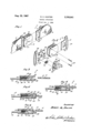
- FIGUREI 1 is a perspective view Iof a buckle structure constructed in accordance with the present invention.
- FIGURE 2 is an exploded View of the structure of FIGURE 1;
- FIGURE 3 is a sectional view of the structure of FIG- URE 1 taken along line 3 3;
- FIGURE 4 is a sectional view similar to FIGURE 3 illustrating engagement of the buckle structure
- FIGURE 5 is a sectional view similar to FIGURE 3 illustrating the buckle structure engaged.
- FIGURE 6 is a sectional view similar to FIGURE 3 illustrating disengagement of the buckle structure.
- FIGURE l there is shown a female clasp 10 aixed to one belt end 12 and a male coupling 14 axed to another 4belt end 16.
- the clasp is simple and clean.
- the for-mer is simply inserted into the latter.
- Stress lapplied across the ⁇ belt ends 12 and 16 will then 4be supported present invention is to probuckle which has relatively manufactured without expensive -by the buckle structure remaining wedded.
- the clasp 10 'includes a flat housing 18 (FIGURE 2) defining a flat space with opposed open ends.
- a pair of slidable members are then atlixed in the housing by rivet pins 20.
- a hook member 22 an-d a latch member 24 are held slidable relative the open ends of the housing by receiving the pins 20 transversely through elongate slots. These pins are riveted in the housing 18.
- the hook member 22 is of flat, generally-rectangular configuration with a belt-coupling integral loop 26. At the end of the member remote from the loop 26, there is formed a catch or hook 27 which is raised from the flat hook member 22.
- a pair of slots 28, through which the pins 20 extend are separated by a larger slot 30 in which a coil spring 31 dwells.
- the hook member slides in flat surface engagement against one wall 32 (FIGURE 3) of the housing 18.
- the opposed wall of the housing 34 is contiguous to a slidably mounted latch member 36 (FIGURES 2 and 3).
- the latch member defines parallel slots 38 which re- ,ceive the pins 20 and a longer central slot 40 which mates with the slot 30 in the hook member to receivably contain the coil spring 31.
- the latch member 36 is of a flat U shape in section, lproviding a central section 42 carrying the spring 31, an-d extending flat end sections 44 and 46, of which the section 46 is somewhat beveled.
- the coil -spring 31 holds the hook member 22 and the latch member 36 in a central position, however, the spring is yielda-ble to permit the hook member 22 to be moved to the right as shown) and the latch member to be moved to the left.
- the coupling 14 is engaged to the clasp 10 by forcing the latch member 24 to the left relative the housing 18, and is released from the clasp by forcing the hook member to the right relative the housing 18.
- the coupling 14 may take various forms; however, as shown it simply comprises a thickness of metal, for example, with the actual coupling section integrally formed with an elongate loop section 49 for attachment to a belt end as shown.
- the belt ends 12 and 16 can be attached to the loop section by stitching or otherwise as well known in the prior art.
- the component parts may be relatively simply formed as by stamping from rather heavy sheet metal stock, for example.
- the hook member 22 can be stamped or punched to simultaneously provide the slots and the hook Z7 therein.
- the coupling 14 and the latch member 36 can be similarly formed, as may the housing 18 by the addition of a forming step to form the housing into a rectangular closure.
- Grip surfaces 51 (FIGURE 1) at the sides of the housing can be for-med yas by grooves or other knurling either during stamping or forming of the housing.
- the components of the clasp 10 can 4be easily assembled, simply by mating the hook member 22 to the latch member 24, with the spring 32 in the slots therein, then placing those units into the housing 18 and setting the rivet pins 20.
- various other forms of pin fasteners can be employed rather than the rivet pins 20 as generally well known in the prior art.
- the unwed clasp 10 and mating coupling 14 are shown in FIGURE 3.
- To couple these members Ithe coupling 14 is forced into the clasp 10, slidably displacing the latch member 36 to the left (FIGURE 4) against the force of the spring 32.
- the attachment coupling 14 drops downward with an audible snap receiving the hook 27 in a mating hook opening 50 in the coupling 14 (FIGURE 5).
- forces applied as indicated by the arrows 52 and 54 in FIGURE 5 are unyieldingly supported by the buckle structure. This support results because of the positive engagement between the hook opening 50 in the coupling 14 and the hook 27 in the hook member 22. Therefore, the buckle can be ⁇ designed to support virtually any practical load.
- the coupling 14 is pulled or urged t-o the right, as shown in FIGURE 6, however, the force is applied not with respect to the -hook 27, but with respect to the housing 18.
- the hook member 22 is slidably displaced to the right, overcoming the force of the spring 32, so that the hook 27 is moved clear to the latch member 36 and the coupling 14 may easily slide out of engagement with the clasp 10.
- the engagement and disengagement occurs quite smoothly and is easily accomplished.
- the beveled end section 46 and the somewhat rounded end of the coupling 14 assists in sliding the members together.
- the hook 27 is slightly tapered to rearward, thus enabling the coupling 14 to raise therefrom.
- the releasing 4operation can be performed with one hand, as in the event of an emergency. This simply involves hold ing the housing 18 in the hand while urging the coupling 14 away from the housing, say with the thumb and one finger.
- the described clasp embodiment includes only four basic operating parts. With simplicity of this degree, the structure may be made very strong, durable and reliable.
- a buckle structure as for releasably locking two belt ends together comprising:
- a housing defining a channel of rigid walls with opposed open ends;
- a hook member slidably aixed contiguous one wall in said channel for movement between said open ends of said channel;
- a latch member slidably affixed contiguous another Wall in said channel -opposed to said one wall for movement between said open ends of said channel;
- a coil spring means xed in a space defined by mating recesses in hook member and said latch member, for urging said first hook member and said latch member in closed relationship between said opposed walls of said channel;
- a hook engaging coupling member insertable into said channel -by forced displacement of said latch member relative to said hook member and releasable therefrom by forced displacement of said hook member relative said latch member.
Landscapes
- Automotive Seat Belt Assembly (AREA)
Description
Allg- 22, 1967 R. A. HUNTER 3,336,641
' l BUCKLE STRUCTURE Filed Jan. 6, 1966 United States Patent() 3,336,641 BUCKLE STRUCTURE Robert A. Hunter, 8 Hockahum Road, Westport, Conn. 06880 Filed Jan. 6, 1966, Ser. No. 519,150 5 Claims. (Cl. Z4-230) The present invention relates to buckles as for use on seat belts and more particularly t-o a buckle that is positive locking yet safe, economical and simple to use.
In recent years, public recognition of the protection provided by seat belts in automobiles, has accounted for very general use of such belts. Of course, such belts have also been in widespread use for many years in aircraft, speed boats and the like. As a result, a wide variety of different belt buckle structures have been proposed over the years. However, a need continues to remain for a buckle structure of universal acceptance.
A seat belt buckle should possess certain characteristic features. Specifically, it should be positive locking (not spring held), it should be simple to operate and of basically sturdy design. Furthermore, a snapping lock with an audible click n closure is desirable to signal the user. Still another desirable feature for `a seat belt buckle is that it be releasable by using only lone hand, as in an emergency. Of course, in addition to these features simplicity of design is always important both as related to reliability and t-o economy of production.
Accordingly, it is an object of the present invention to provide an improved fbuckle, as for seat -belt use, which generally possesses the desirable characteristics for such buckles as considered above.
Another object of the present invention is to provide an improved buckle structure which is positive locking, rugged, simple to operate and yet capable of being embodied in a unit which can be very economically manufactured.
Still another object of the vide an improved seat belt few parts, which can be tooling or the like.
One further objectl of the present invention is to provide an improved seat belt buckle which has a clean unobstructed appearance, and which is simple in use and manufacture, yet rugged and positive-locking.
Additional objects and advantages of the present invention will become apparent from a consideration of the following description taken in conjunction with the accompanying drawings which are presented by way of example only and are not intended as a limitation upon the scope of the present invention as defined in the appended claims, and in which:
FIGUREI 1 is a perspective view Iof a buckle structure constructed in accordance with the present invention;
FIGURE 2 is an exploded View of the structure of FIGURE 1;
FIGURE 3 is a sectional view of the structure of FIG- URE 1 taken along line 3 3;
FIGURE 4 is a sectional view similar to FIGURE 3 illustrating engagement of the buckle structure;
FIGURE 5 is a sectional view similar to FIGURE 3 illustrating the buckle structure engaged; and
FIGURE 6 is a sectional view similar to FIGURE 3 illustrating disengagement of the buckle structure.
Referring now to FIGURE l, there is shown a female clasp 10 aixed to one belt end 12 and a male coupling 14 axed to another 4belt end 16. As shown, the clasp is simple and clean. To engage the coupling 14 to the clasp 10, the for-mer is simply inserted into the latter. Stress lapplied across the `belt ends 12 and 16 will then 4be supported present invention is to probuckle which has relatively manufactured without expensive -by the buckle structure remaining wedded. Disengaging Considering the structure in greater detail, the clasp 10 'includes a flat housing 18 (FIGURE 2) defining a flat space with opposed open ends. A pair of slidable members are then atlixed in the housing by rivet pins 20. Specifically, a hook member 22 an-d a latch member 24 are held slidable relative the open ends of the housing by receiving the pins 20 transversely through elongate slots. These pins are riveted in the housing 18.
The hook member 22 is of flat, generally-rectangular configuration with a belt-coupling integral loop 26. At the end of the member remote from the loop 26, there is formed a catch or hook 27 which is raised from the flat hook member 22. A pair of slots 28, through which the pins 20 extend are separated by a larger slot 30 in which a coil spring 31 dwells.
The hook member slides in flat surface engagement against one wall 32 (FIGURE 3) of the housing 18. The opposed wall of the housing 34 is contiguous to a slidably mounted latch member 36 (FIGURES 2 and 3). The latch member defines parallel slots 38 which re- ,ceive the pins 20 and a longer central slot 40 which mates with the slot 30 in the hook member to receivably contain the coil spring 31. The latch member 36 is of a flat U shape in section, lproviding a central section 42 carrying the spring 31, an-d extending flat end sections 44 and 46, of which the section 46 is somewhat beveled.
In the operation of the structure, the coil -spring 31 holds the hook member 22 and the latch member 36 in a central position, however, the spring is yielda-ble to permit the hook member 22 to be moved to the right as shown) and the latch member to be moved to the left. Thus, the coupling 14 is engaged to the clasp 10 by forcing the latch member 24 to the left relative the housing 18, and is released from the clasp by forcing the hook member to the right relative the housing 18.
The coupling 14 may take various forms; however, as shown it simply comprises a thickness of metal, for example, with the actual coupling section integrally formed with an elongate loop section 49 for attachment to a belt end as shown. The belt ends 12 and 16 can be attached to the loop section by stitching or otherwise as well known in the prior art.
In producing the Istructure illustratively described herein, the component parts may be relatively simply formed as by stamping from rather heavy sheet metal stock, for example. Specifically, the hook member 22 can be stamped or punched to simultaneously provide the slots and the hook Z7 therein. The coupling 14 and the latch member 36 can be similarly formed, as may the housing 18 by the addition of a forming step to form the housing into a rectangular closure. Grip surfaces 51 (FIGURE 1) at the sides of the housing can be for-med yas by grooves or other knurling either during stamping or forming of the housing.
The components of the clasp 10 can 4be easily assembled, simply by mating the hook member 22 to the latch member 24, with the spring 32 in the slots therein, then placing those units into the housing 18 and setting the rivet pins 20. Of course various other forms of pin fasteners can be employed rather than the rivet pins 20 as generally well known in the prior art.
Considering the operation of the buckle structure in detail, the unwed clasp 10 and mating coupling 14 are shown in FIGURE 3. To couple these members, Ithe coupling 14 is forced into the clasp 10, slidably displacing the latch member 36 to the left (FIGURE 4) against the force of the spring 32. When the latch member 36 is moved sufficiently to the left, the attachment coupling 14 drops downward with an audible snap receiving the hook 27 in a mating hook opening 50 in the coupling 14 (FIGURE 5). In this manner, the members are wedded and it is to be noted that forces applied as indicated by the arrows 52 and 54 in FIGURE 5, are unyieldingly supported by the buckle structure. This support results because of the positive engagement between the hook opening 50 in the coupling 14 and the hook 27 in the hook member 22. Therefore, the buckle can be `designed to support virtually any practical load.
To release the buckle, the coupling 14 is pulled or urged t-o the right, as shown in FIGURE 6, however, the force is applied not with respect to the -hook 27, but with respect to the housing 18. As a result, the hook member 22 is slidably displaced to the right, overcoming the force of the spring 32, so that the hook 27 is moved clear to the latch member 36 and the coupling 14 may easily slide out of engagement with the clasp 10.
In the operation of the :buckle structure, the engagement and disengagement occurs quite smoothly and is easily accomplished. In this regard, the beveled end section 46 and the somewhat rounded end of the coupling 14 assists in sliding the members together. In separating the members, it is to be noted that the hook 27 is slightly tapered to rearward, thus enabling the coupling 14 to raise therefrom.
Somewhat related to the ease with which the buckle can be mated and released, is the consideration that the releasing 4operation can be performed with one hand, as in the event of an emergency. This simply involves hold ing the housing 18 in the hand while urging the coupling 14 away from the housing, say with the thumb and one finger.
Another important feature of the invention resides in the simplicity with which structures embodying the invention can be produced. Specifically for example, the described clasp embodiment includes only four basic operating parts. With simplicity of this degree, the structure may be made very strong, durable and reliable.
Of course, as stated, various means can be employed with the basic structure hereof for attaching the buckle to belt ends and such devices can readily include adjustment means to vary the length of useful belt if desired.
These and other important features and advantages of the present invention will be apparent to those skilled in the art of buckles and the like, and furthermore various other structural embodiments hereof will also be apparent to such persons. Therefore, it is emphasized that the present invention is not to be limited in accordance with the foregoing illustrative example but shall be determined in accordance with the claims set forth below.
What is claimed is:
1. A buckle structure as for releasably locking two belt ends together, comprising:
a housing defining a channel of rigid walls with opposed open ends;
a hook member slidably aixed contiguous one wall in said channel for movement between said open ends of said channel;
a latch member slidably affixed contiguous another Wall in said channel -opposed to said one wall for movement between said open ends of said channel;
a coil spring means xed in a space defined by mating recesses in hook member and said latch member, for urging said first hook member and said latch member in closed relationship between said opposed walls of said channel; and
a hook engaging coupling member insertable into said channel -by forced displacement of said latch member relative to said hook member and releasable therefrom by forced displacement of said hook member relative said latch member.
2. A structure according to claim 1 wherein said housing comprises a substantially at rectangular closure defining external grip surfaces.
3. A structure according to claim 1 wherein said hook member comprises a substantially flat plate of somewhat rectangular configuration and said hook-engaging coupling member comprises a substantially flat plate defining an opening for engagement with said hook member.
4. A structure according to claim 3 wherein said hook member and said coupling member each include means for alxing a belt thereto.
5. A structure according to claim 1 wherein said hook member and said latch member are affixed to said housing by common pin means extending through elongate slots in said hook member and said latch member and xed in said housing.
References Cited UNITED STATES PATENTS 1,202,550 10/1965 Germany.
920,365 3/1963 Great Britain.
BERNARD A. GELAK, Primary Examiner.
Claims (1)
1. A BUCKLE STRUCTURE AS FOR RELEASABLY LOCKING TWO BELT ENDS TOGETHER, COMPRISING: A HOUSING DEFINING A CHANNEL OF RIGID WALLS WITH OPPOSED OPEN ENDS; A HOOK MEMBER SLIDABLY AFFIXED CONTIGUOUS ONE WALL IN SAID CHANNEL FOR MOVEMENT BETWEEN SAID OPEN ENDS OF SAID CHANNEL; A LATCH MEMBER SLIDABLY AFFIXED CONTIGUOUS ANOTHER WALL IN SAID CHANNEL OPPOSED TO SAID ONE WALL FOR MOVEMENT BETWEEN SAID OPEN ENDS OF SAID CHANNEL; A COIL SPRING MEANS FIXED IN A SPACE DEFINED BY MATING RECESSES IN HOOK MEMBER AND SAID LATCH MEMBER, FOR URGING SAID FIRST HOOK MEMBER AND SAID LATCH MEMBER IN CLOSED RELATIONSHIP BETWEEN SAID OPPOSED WALLS OF SAID CHANNEL; AND A HOOK ENGAGING COUPLING MEMBER INSERTABLE INTO SAID CHANNEL BY FORCED DISPLACEMENT OF SAID LATCH MEMBER RELATIVE TO SAID HOOK MEMBER AND RELEASABLE THEREFROM BY FORCED DISPLACEMENT OF SAID HOOK MEMBER RELATIVE SAID LATCH MEMBER.
Priority Applications (1)
| Application Number | Priority Date | Filing Date | Title |
|---|---|---|---|
| US519150A US3336641A (en) | 1966-01-06 | 1966-01-06 | Buckle structure |
Applications Claiming Priority (1)
| Application Number | Priority Date | Filing Date | Title |
|---|---|---|---|
| US519150A US3336641A (en) | 1966-01-06 | 1966-01-06 | Buckle structure |
Publications (1)
| Publication Number | Publication Date |
|---|---|
| US3336641A true US3336641A (en) | 1967-08-22 |
Family
ID=24067060
Family Applications (1)
| Application Number | Title | Priority Date | Filing Date |
|---|---|---|---|
| US519150A Expired - Lifetime US3336641A (en) | 1966-01-06 | 1966-01-06 | Buckle structure |
Country Status (1)
| Country | Link |
|---|---|
| US (1) | US3336641A (en) |
Cited By (15)
| Publication number | Priority date | Publication date | Assignee | Title |
|---|---|---|---|---|
| US3897611A (en) * | 1972-10-02 | 1975-08-05 | Allied Chem | Ejection tongue for buckle |
| US4069558A (en) * | 1975-11-10 | 1978-01-24 | Ray Eberhart | Latch mechanism |
| USD269389S (en) | 1980-07-17 | 1983-06-21 | Wood Kenneth H | Buckle for safety belt or harness |
| US4567629A (en) * | 1983-02-07 | 1986-02-04 | Kabushiki Kaisha Toka-Rika-Denki-Seisakusho | Buckle device |
| USD285383S (en) | 1985-08-23 | 1986-09-02 | Indiana Mills & Manufacturing, Inc. | Seat belt T-bar |
| USD287187S (en) | 1984-02-17 | 1986-12-16 | Olson Craig W | Belt buckle or similar article |
| USD292192S (en) | 1985-03-18 | 1987-10-06 | Nippon Notion Kogyo Co. Ltd. | Belt buckle |
| USD292898S (en) | 1984-11-28 | 1987-11-24 | Nippon Notion Kogyo Co. Ltd. | Buckle |
| US4744134A (en) * | 1985-11-20 | 1988-05-17 | Aciers Et Outillage Peugeot | Safety belt buckle, particularly for automobiles |
| USD338390S (en) | 1990-09-25 | 1993-08-17 | Yoshida Kogyo K.K. | Belt adjuster used on suspenders for clothing |
| US5426834A (en) * | 1993-03-26 | 1995-06-27 | Alliedsignal Inc. | End release seat belt buckle |
| US20150135483A1 (en) * | 2012-06-06 | 2015-05-21 | Illinois Tool Works Inc. | Multi-directional buckle assembly |
| EP2489409A3 (en) * | 2011-02-17 | 2018-01-17 | Löwenstein Medical Technology S.A. | Mounting device for a banding |
| USD888612S1 (en) * | 2018-05-17 | 2020-06-30 | Radio Systems Corporation | Nesting seatbelt tongue |
| USD1050947S1 (en) * | 2024-08-08 | 2024-11-12 | Fengyi Li | Seat belt buckle |
Citations (4)
| Publication number | Priority date | Publication date | Assignee | Title |
|---|---|---|---|---|
| GB920365A (en) * | 1960-02-23 | 1963-03-06 | Andrew Gray Carter | Improvements in buckles for safety belts |
| FR1330150A (en) * | 1962-02-06 | 1963-06-21 | Ed Vaux Ets | Improvements made to seat belts for motor vehicles or aircraft |
| US3130466A (en) * | 1961-02-06 | 1964-04-28 | Andrew G Carter | Simplified slide-action buckle mechanism |
| DE1202550B (en) * | 1961-09-25 | 1965-10-07 | Robert Schwartzkopff | Closure buckle, especially for safety belts in motor vehicles |
-
1966
- 1966-01-06 US US519150A patent/US3336641A/en not_active Expired - Lifetime
Patent Citations (4)
| Publication number | Priority date | Publication date | Assignee | Title |
|---|---|---|---|---|
| GB920365A (en) * | 1960-02-23 | 1963-03-06 | Andrew Gray Carter | Improvements in buckles for safety belts |
| US3130466A (en) * | 1961-02-06 | 1964-04-28 | Andrew G Carter | Simplified slide-action buckle mechanism |
| DE1202550B (en) * | 1961-09-25 | 1965-10-07 | Robert Schwartzkopff | Closure buckle, especially for safety belts in motor vehicles |
| FR1330150A (en) * | 1962-02-06 | 1963-06-21 | Ed Vaux Ets | Improvements made to seat belts for motor vehicles or aircraft |
Cited By (16)
| Publication number | Priority date | Publication date | Assignee | Title |
|---|---|---|---|---|
| US3897611A (en) * | 1972-10-02 | 1975-08-05 | Allied Chem | Ejection tongue for buckle |
| US4069558A (en) * | 1975-11-10 | 1978-01-24 | Ray Eberhart | Latch mechanism |
| USD269389S (en) | 1980-07-17 | 1983-06-21 | Wood Kenneth H | Buckle for safety belt or harness |
| US4567629A (en) * | 1983-02-07 | 1986-02-04 | Kabushiki Kaisha Toka-Rika-Denki-Seisakusho | Buckle device |
| USD287187S (en) | 1984-02-17 | 1986-12-16 | Olson Craig W | Belt buckle or similar article |
| USD292898S (en) | 1984-11-28 | 1987-11-24 | Nippon Notion Kogyo Co. Ltd. | Buckle |
| USD292192S (en) | 1985-03-18 | 1987-10-06 | Nippon Notion Kogyo Co. Ltd. | Belt buckle |
| USD285383S (en) | 1985-08-23 | 1986-09-02 | Indiana Mills & Manufacturing, Inc. | Seat belt T-bar |
| US4744134A (en) * | 1985-11-20 | 1988-05-17 | Aciers Et Outillage Peugeot | Safety belt buckle, particularly for automobiles |
| USD338390S (en) | 1990-09-25 | 1993-08-17 | Yoshida Kogyo K.K. | Belt adjuster used on suspenders for clothing |
| US5426834A (en) * | 1993-03-26 | 1995-06-27 | Alliedsignal Inc. | End release seat belt buckle |
| EP2489409A3 (en) * | 2011-02-17 | 2018-01-17 | Löwenstein Medical Technology S.A. | Mounting device for a banding |
| US20150135483A1 (en) * | 2012-06-06 | 2015-05-21 | Illinois Tool Works Inc. | Multi-directional buckle assembly |
| US9125458B2 (en) * | 2012-06-06 | 2015-09-08 | Illinois Tool Works Inc. | Multi-directional buckle assembly |
| USD888612S1 (en) * | 2018-05-17 | 2020-06-30 | Radio Systems Corporation | Nesting seatbelt tongue |
| USD1050947S1 (en) * | 2024-08-08 | 2024-11-12 | Fengyi Li | Seat belt buckle |
Similar Documents
| Publication | Publication Date | Title |
|---|---|---|
| US3336641A (en) | Buckle structure | |
| US4831694A (en) | Buckle having external finger grip | |
| EP1284613B1 (en) | Fasteners incorporating a whistle | |
| US3605210A (en) | Side locking seat belt buckle | |
| US5203058A (en) | Twin buckle for fastening straps and the like | |
| US5584105A (en) | Quick disconnect buckle | |
| US4282634A (en) | Buckle | |
| US4800629A (en) | Plastic buckle | |
| US9415247B2 (en) | Quick release connector for fall protection | |
| US6868591B2 (en) | Infant buckle | |
| US5774956A (en) | High-security buckle | |
| US8281464B2 (en) | Buckle | |
| US4793032A (en) | Side release buckle | |
| CN113056394A (en) | Seat belt apparatus and buckle | |
| US11375778B1 (en) | Buckle with secondary latch | |
| CA2339067A1 (en) | Safety snap buckle | |
| US6145172A (en) | Locking device for a side-release buckle | |
| US4631787A (en) | Buckle having manually releasable interlocking male and female portions | |
| US3218685A (en) | Buckle for safety belt | |
| US10413024B2 (en) | Fastening structure | |
| US3585692A (en) | Safety belt buckles | |
| JPS6029205B2 (en) | latching device | |
| US4751772A (en) | Two part waist buckle with snap-fitting retention feature | |
| US3131451A (en) | Safety belt buckle | |
| US4407049A (en) | Buckle for belts or the like |