US3234459A - Method and apparatus for locating faults in electrical cable lines by comparing the impedance of the entire faulted line to the impedance of a section of the line - Google Patents
Method and apparatus for locating faults in electrical cable lines by comparing the impedance of the entire faulted line to the impedance of a section of the line Download PDFInfo
- Publication number
- US3234459A US3234459A US784709A US78470959A US3234459A US 3234459 A US3234459 A US 3234459A US 784709 A US784709 A US 784709A US 78470959 A US78470959 A US 78470959A US 3234459 A US3234459 A US 3234459A
- Authority
- US
- United States
- Prior art keywords
- line
- conductor
- impedance
- conductors
- capacitance
- Prior art date
- Legal status (The legal status is an assumption and is not a legal conclusion. Google has not performed a legal analysis and makes no representation as to the accuracy of the status listed.)
- Expired - Lifetime
Links
- 238000000034 method Methods 0.000 title claims description 27
- 239000004020 conductor Substances 0.000 claims description 106
- 238000012360 testing method Methods 0.000 description 33
- 238000005259 measurement Methods 0.000 description 32
- 210000004899 c-terminal region Anatomy 0.000 description 5
- 230000000694 effects Effects 0.000 description 5
- 230000005284 excitation Effects 0.000 description 5
- 239000003990 capacitor Substances 0.000 description 4
- 238000010276 construction Methods 0.000 description 3
- 238000010586 diagram Methods 0.000 description 3
- 230000014509 gene expression Effects 0.000 description 3
- 238000009413 insulation Methods 0.000 description 3
- 235000018734 Sambucus australis Nutrition 0.000 description 1
- 244000180577 Sambucus australis Species 0.000 description 1
- 238000012937 correction Methods 0.000 description 1
- 238000012552 review Methods 0.000 description 1
- 230000035945 sensitivity Effects 0.000 description 1
Images

Classifications
-
- G—PHYSICS
- G01—MEASURING; TESTING
- G01R—MEASURING ELECTRIC VARIABLES; MEASURING MAGNETIC VARIABLES
- G01R31/00—Arrangements for testing electric properties; Arrangements for locating electric faults; Arrangements for electrical testing characterised by what is being tested not provided for elsewhere
- G01R31/08—Locating faults in cables, transmission lines, or networks
Definitions
- This invention relates to an improved method and apparatus for locating faults in electrical cables and the like. More particularly, it relates to a simple, easy-touse method and apparatus capable of accurate location of shorts and opens by comparing the impedance of the entire faulted line to the impedance of the section of line between the point of measurement and the fault.
- a popular system for detecting short circuits is the Murray loop, in which the resistance between the fault and one end of the faulted line is compared with the resistance of another line in the same cable.
- the use of this system involves a basic assumption, viz, that the resistance of the standard, i.e., the other line, bears the same relationship to line length as the resistance of the measured section of the faulted line.
- the cross sections of wires of the same gauge vary within relatively wide tolerance limits, and even conductors in the same cable exhibit a relatively wide range of resistance per unit length, since they are drawn through different dies.
- a more accurate method of locating shorts is the socalled Three Varley Method.
- Three measurements are made of various combinations of the faulted conductor, the conductor to which it is shorted and another conductor.
- the distance to the fault is then computed by multiplying this ratio by the total length of the line. Since the resistance per unit length of a conductor does not vary appreciably along the length thereof, the inaccuracies of the Murray loop are largely eliminated.
- fault location is desirably performed by relatively unskilled labor, and it has been found that numerous errors have resulted from the several measurements reice quired and the computations which must be made for a determination of the distance of the fault.
- Another troublesome factor stems from the necessity of a balance of the bridge circuit; sometimes balance cannot be obtained, requiring a change in the connections for the particular measurement.
- the invention accordingly comprises the several steps and the relation of one or more of such steps with respect to each of the others, and the apparatus embodying the features of construction, combinations of elements and arrangements of parts which are adapted to effect such steps, all as exemplified in the following detailed disclosure, and the scope of the invention will be indicated in the claims.
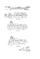
- FIGURE 1 is a schematic diagram of a test set circuit adapted for fault location according to my invention
- FIGURES 2 and 3 are simplified schematic circuit diagrams showing the operation of the test set of FIGURE 1 in locating a short circuit
- FIGURES 4 and 5 are simplified schematic circuit dia grams showing the operation of the test set of FIGURE 1 in locating an open circuit.
- my invention operates to locate a fault by comparing an impedance of the entire faulted line with the impedance of a section between the fault and one end of the line.
- the ratio between these impedance is the fractional distance of the fault from the end of the line at which the measurements are made.
- the impedance utilized is the resistance of the line, and where a break or open circuit is to be located, the capacitance between the line and another conductor is utilized.
- the measurements involved require the balancing of a simple bridge circuit by moving the tap of a potentiometer forming two arms of a simple bridge circuit. The faulted conductors and other conductors form the other arms.
- the present invention requires but two measurements.
- One of these determines the ratio of the impedance of the section between the test set and the fault to the sum of the impedances of the entire faulted line and another line.
- the other determines a ratio relating the impedance of the section in question to another impedance including that of the other line.
- Conductor 12 may be another line in the same cable as line It) or in another cable, or it may be the cable armor or sheath or even the ground itself, and thus the term conductor, as used herein and in the claims, is not restricted to any particular form of electrically conducting medium.
- short circuit includes high resistance paths between conductors, since these, as well as low resistance connections, are susceptible of accurate location by the system to be described. Two more conductors, 1'6 and 18, extend along.
- a test set generally indicated at 20 includes a potentiometer '22 with a tap'24.
- the tap is mechanically linked to a dial 26 calibrated in terms of the ratio, R /R, oi the resistance R te the tap 24 and one end 27 of the potentiometer 2.2 to'th'e entire resistance R of the potentiometer.
- a sensitive current or voltmeter 28 is connected across potentiometer 22 between a pair of terminals X and Y.
- the test set is completed for the measurements of FIGURES 2' and 3 by a battery 30 connected between the tap 24 and athird terminal C.
- a firstmeasurement is madeby connecting the apparatus as shown in FIGURE 3 with the Y and X terminals connectedto line It) and conductor 16' and the C terminal connectedto conductor 18.
- the resulting bridge circuit includes the portions of the potentiometer 22' on either side oft'he tap'24'as two of its arms; and the line 10 and conductor 1 6 are the other two arms.
- the bridge is brought to-bala'nce' asindicated by'a' null reading of the met'er-28,-and the readingof 'the'dial '26"provides the information,
- Rltlg is the resistance of the remainder of the line 10
- R16 is'the resistance of'the conductor 16.
- the C terminal'of the test set 20 is then moved to the conductor 1-2-fora second' measurement, as'shown in FIG- URE 2.
- two arms of the bridge are, asbefore, the twoportionsof the potentiometer 22 on either side -of the tap 24.
- One of the'remaining arms consists of theresistance R19 and the other, resistances R10 and-R16-.
- the latter fraction l/L is the fractional distance of the fault '14'from the near end of the line ltl connected to the test set 20. Multiplication of this fraction by the known length L of the faulted line gives the actual distance of the fault 14 in units of length.
- the faulted line 10 may comprise two conductors 10a and 10b (FIGURES 2 and 3) of different sizes or gauges. In that event, the line would. be termed a mixed gauge line having two mixed gauges as shown.
- the location of a fault in a mixed gauge line, by my invention, involves the same measurements as those described above for a single gauge use, The connections and readings taken are exactly the same. However, the computation is somewhat dilfernt.
- fault 14 is in the seco nd section Nb, and this would be indicated by a value of K greater than 1 L1 +111 L2
- the distance to the fault would be given by Again, the computations required are simpler than those used in other fault locating systems capable of reasonable accuracy.
- FIGURES 4 and 5 I have illustrated a line32 liaving a fault 34 in the form of a break or open circuit to be located by useof the test set 20. Conductors 36, 38 and at) extending between the ends of the faulted line 32 are also used in the requiredmeasurements.
- the test set Ztt utilizes an alternating current generator illustratively indicated at 42 in place of' the battery 30 of FIGURES 2 and 3 in order to make use of the capacitances between certain of the conductors in determining the distance l to the fault 34.
- Equation 9 is the ratio of the capacitance of section 32a of the faulted line 32 to the entire capacitance between the line and conductor 36 and is therefore equal to the fractional distance, 1/1. of the fault 34 from the near end of line 32.
- the two measurements described above may also be used in locating a break in a mixed capacitance line, i.e.,
- the measured value of K will be less than
- L is the length of the remote segment
- N is the nominal capacitance per unit length between the line 32 and conductor 36 in the near segment divided by the nominal capacitance between the line and conductor 36 in the remote segment
- the distance thereof fromthe test set is given by If the break is in the remote segment, the distance is given y 1 PK L 2V PK+P-K) 1T
- the jumper connections 44 and 46 at the remote ends of the conductors may, of course, be made by latching type relays energized from the end at which the test set measurements are made.
- the battery 30 is connected in series with a variable sensitivity adjusting resistor 48.
- the generator 42 takes the form of an oscillator connected between the C terminal and contact S1 of a switch S1, while battery 30 is connected to a contact SI
- the movable contact or wiper Si of switch S1 is connected to the sliding tap 24 of potentiometer 22, and thus the excitation of the bridge circuit of which potentiometer 22 is a part may be changed from alternating to direct-current by proper setting of this switch.
- the meter 28 is connected between the X terminal and the movable contact S2 of a switch S2.
- a contact S2 is connected to the Y terminal, and a contact S2,, is connected to the output of an amplifier 59 whose input is derived from the voltage between the X and Y terminals.
- the X terminal is grounded to a chassis in the test set as indicated at 62, the latter being isolated from the actual earth ground.
- an oscillator 64 whose frequency is the same as that of generator 42, is connected in series with a capacitor 66 between the tap 24 and chassis ground 62.
- the amplifier 50 preferably includes a suitable rectifier so that the meter 28. connected to its output may be a direct current meter of suitable construction.
- test set 20 is arranged as shown in simplified form in FIGURES 4 and 5, adapted for location of a break in a conductor.
- switches which may be ganged for ease of manipulation are in the other or b. positions, the test set circuit of FIGURES 1 and 2 is achieved.
- oscillator 64 and capacitor 66 The purpose of oscillator 64 and capacitor 66 is to eliminate the effect of the capacitance between the test set and actual ground. Stray capacitances always exist between the test set chassis (and the X terminal connectod thereto) and the earth, :and also between the earth and the conductors connected to the C and Y terminals. In fact, the conductor 36 or 38 (FIGURES 4 and 5) may in some instances be the earth or cable armor in electrical contact therewith. Thus, there are resultant stray :capacitances between the X terminal and the C and Y terminals.
- the stray capacitance (not shown) between the X and Y terminals is across the entire potentiometer 22 and therefore does not affect balance of the measuring bridge circuit.
- the stray capacitance (not shown) between the X and C terminals is in parallel with the capacitance C1 and therefore will afiect bridge balance and result in inaccurate measurement of the I ratio
- the oscillator 64 operates at the same frequency as oscillator 42 and in phase opposition therewith, as indicated bythe polarity signs. Accordingly, oscillator 64 applies a signal between the X terminal and tap 24 in phase opposition to the current from generator 42 between these points through the stray capacitances.
- Capacitor 66 is adjusted so that the two currents are equal in magnitude, thereby cancelling the effect of such icapacitances. In practice, I have found enemy in view of these factors. spurious signals are received,rmeans should be provided being from the :same endof the.line.
- that'capacitor '66 maybe set in the factory and remain fixed thereafter in most applications. It will be apparent .that oscillator 64and generator 42 may be combined, so long as the .respective outputs are isolated sufliciently from each other.
- the capacitance cancelling feature vof the test set 20 is als0.offirnportance in making certain measurements, other than Lthosedescribd above, wherein the test set isused as a straight capacitance bridge for more direct measurement of the capacitance ratios in a broken line.
- This latter type 'of measurement is often made where a line has two breaks, and the distance to one from one end ofrthe line is, known.
- FIGURES 4. and 5 it should be noted at this point that voltages will be jinducedby the excitation from the generator 42 in other conductors (not shown) capacitively coupled to those used in themeasurements. However, these signals have no effect .on the measurements taken with my system inasmuch. as they are. self-cancelling in nature.
- the frequenc er the generator 42 should be sufficiently low that the reactances of the measured capacitancesaresubstantiallyfless than the resistances and self inductances of the conductors used in the measurements,
- thefrequency should be different from that ofany stray 'spurious signals which may be picked by the conductors used inthe measurements, most notably, the standard-power line frequency of 60 cycles per/second and harmonics thereof. I have found that .100 cycles per second is awsuitable excitation fre- Moreover, when such to difierentiate them from the bridge unbalance signal; and, accordingly, earphones 'may' be substituted for the rmeter 28-and the. amplifier50, whereby the operator may determine by ear when an actual bridge mill is obtained.
- the faults are located by comparing an impedance of the section of the faulted line between thefault and the test set to the impedance of theentireline, thereby affording a high degree of accuracy.
- the impedanceutili'zed is the electrical resist-anceof the line
- the impedance utilized is vthe capacitance between the conductor and other conductors extending parallel thereto. In either case, but two measurements .arerequiredboth of these From the readings. obtained, the fractional distances.
- said. potentiometer having a.rnovable tap, whereby the potentiometer impedances oneither side'of' said tapand the line capacitances connected to s'aidpotentiometer form a bridge circuit,.said method 'alsdincludirigthe application of excitation between a pair. ofopposite terminals of said bridge circuit ,and the adjustment 'of'said tap to provide a null voltage between the remaining terminals of said bridge.
- a method for locating a fault in the form of a break or the like in a first conductor that extends from either side of said break between near and far ends said method locating said break from said near end of said first conductor by comparing a first capacitance consisting of the capacitance between the section of said first conductor between said near end and said fault and a second conductor co-extensive with said first conductor between said near and far ends with the entire capacitance between said first and second conductors, the steps of connecting said first and second conductors with a third conductor co-extensive with said first conductor between said near and far ends and with two relatively inverselyvariable impedance elements to form a first bridge circuit that can be balanced to measure, as a first number N1, the ratio of said first capacitance to the sum of said entire capacitance plus the capacitance between said second and third conductors, and connecting said first and third conductors with said impedance elements to form a second bridge circuit that can be balanced to measure, as
- test set adapted for location of a fault in an electrical conductor, said test set comprising, in combination, a potentiometer having first and second ends and a movable tap, a first terminal connected to said first end of said potentiometer and a second terminal connected to said second end thereof, indicating means adapted to indicate the proportion of the entire impedance of said potentiometer between said tap and one of said ends, a third terminal, a direct-current source and a first alternating-current source, means for alternatively connecting said sources between said tap and said third terminal, voltage indicating means connected .to said first and second ends of said potentiometer and adapted thereby to determine the voltage across said potentiometer, said first end of said potentiometer being connected to a metallic chassis in said test set, and a second
- said second alternating-current source includes an oscillator whose output is in series with a variable impedance element, thereby to facilitate adjustment of the characteristics of said compensating signal.
Landscapes
- Physics & Mathematics (AREA)
- General Physics & Mathematics (AREA)
- Locating Faults (AREA)
Description
Feb. 8, 1966.
Filed Jan. 2, 1959 J. METHOD AND APPARATUS FOR A. BRAZEE LOCATING FAULTS IN ELECTRICAL CABLE LINES BY COMPARING THE IMPEDANCE OF THE ENTIRE FAULTED LINE TO THE IMPEDANCE OF A SECTION OF THE LINE 2 Sheets-Sheet 1 :1: OSCILLATOR 30 fig 64 0 L A v 0 ll. C\ s OSCILLATOR I j l 42 F l G. I
so I 2? C l2 I'l D l4- D i Y IO. 2"; IO R loo lOb 28 Rl6 i/ ls 24 22 F l G. 2
INVENTOR.
JOHN A. BRAZEE BY w gdfimfifm ATTORNEYS J. A. BRAZEE Feb. 8, 1966 METHOD AND APPARATUS FOR LOGATING FAULTS IN ELECTRICAL CABLE LINES BY COMPARING THE IMPEDANCE OF THE ENTIRE FAULTED LINE TO THE IMPEDANCE OF A SECTION OF THE LINE 3 Sheets-Sheet 2 Filed Jan. 2, 1959 IOGJ |ob- F l G. 3
F I G. 4
INVENTOR.
JOHN A. BRAZEE ATTORNEYS United States Patent 3 234,459 METHQD AND APPARATUS FOR LOCATING FAULTS IN ELECTRICAL CABLE LINES BY COMPARING THE IMPEDANCE 0E THE ENTERE FAULTED LINE TO THE HMPEDANCE 0F A SECTION OF THE LINE John A. Brazee, Wallingford, Conn, assignor to Whitney Blake Company, New Haven, Conn. Fiied Jan. 2, 1959, Ser. No. 784,799 Claims. (Cl. 32452) This invention relates to an improved method and apparatus for locating faults in electrical cables and the like. More particularly, it relates to a simple, easy-touse method and apparatus capable of accurate location of shorts and opens by comparing the impedance of the entire faulted line to the impedance of the section of line between the point of measurement and the fault.
It is well known that the resistance of an electrical conductor varies in direct proportion to its length. Further, the capacitance between the conductor and another conductor in the same cable varies in the same manner, since the spacing between the two conductors, indeed between all other conductors in the cable, is constant throughout its length. Accordingly, it is possible to locate a fault in a conductor by comparing the resistance or capacitance of the section between the fault and one end of the conductor with a standard impedance of known relationship to the length of the line. Ordinarily, capacitance measurements are used for location of breaks and resistance measurements for the location of short circuits; and the measurements are made with bridge circuits which compare the impedance involved in a wellknown manner.
A popular system for detecting short circuits is the Murray loop, in which the resistance between the fault and one end of the faulted line is compared with the resistance of another line in the same cable. The use of this system involves a basic assumption, viz, that the resistance of the standard, i.e., the other line, bears the same relationship to line length as the resistance of the measured section of the faulted line. However, the cross sections of wires of the same gauge vary within relatively wide tolerance limits, and even conductors in the same cable exhibit a relatively wide range of resistance per unit length, since they are drawn through different dies. Furthermore, it may not be feasible to use, as a standard, a line in the same cable, and if another line paralleling the faulted conductor is used, its temperature may be different, thereby adding a further element of error. Also, in many cases it is desirable to make the measurements at a test station in a telephone exchange or the like, from which lead wires connect the faulted cable to the point of measurement. This requires additional computation to eliminate the effect of lead resistance.
A more accurate method of locating shorts is the socalled Three Varley Method. Three measurements are made of various combinations of the faulted conductor, the conductor to which it is shorted and another conductor. By subtraction and division of the results of the various measurements, one may arrive at the ratio of the resistance from the point of measurement to the fault to the entire resistance of the faulted line. The distance to the fault is then computed by multiplying this ratio by the total length of the line. Since the resistance per unit length of a conductor does not vary appreciably along the length thereof, the inaccuracies of the Murray loop are largely eliminated. However, fault location is desirably performed by relatively unskilled labor, and it has been found that numerous errors have resulted from the several measurements reice quired and the computations which must be made for a determination of the distance of the fault. Another troublesome factor stems from the necessity of a balance of the bridge circuit; sometimes balance cannot be obtained, requiring a change in the connections for the particular measurement.
The location of breaks has heretofore been accomplished by comparing the capacitance between a section of the faulted conductor and "another conductor with the capacitance between another pair of conductors in the same cable. As with resistance, the capacitances between pairs of conductors in a cable may vary rather widely, and therefore these prior systems have been subject to large inaccuracies. It should be noted that an error of as little as a hundred feet in the measured location of a fault in an armored cable suspended on poles or buried in the ground can result in considerable additional expenditure in arriving at its actual location and correction.
Accordingly, it is a principal object of my invention to provide an improved method and apparatus for accurate location of faults in electrical conductors. It is another object of my invention to provide a method and apparatus of the above character capable of locating both short and open circuit faults. A further object of the present invention is to provide a method and apparatus of the above character requiring a minimum number of simple measurements and computations, and thereby lending itself to expeditious operation by unskilled personnel. A still further object of the invention is to provide a method and apparatus of the above character capable of fault location in a line comprising serially connected conductors of different sizes. Yet another object of the invention is to provide apparatus of the above character having high precision and yet readily constructed of relatively low cost components. Other objects of the invention will in part be obvious and will in part appear hereinafter.
The invention accordingly comprises the several steps and the relation of one or more of such steps with respect to each of the others, and the apparatus embodying the features of construction, combinations of elements and arrangements of parts which are adapted to effect such steps, all as exemplified in the following detailed disclosure, and the scope of the invention will be indicated in the claims.
For a fuller understanding of the nature and objects of the invention, reference should be had to the following detailed description taken in connection with the accompanying drawings, in which:
FIGURE 1 is a schematic diagram of a test set circuit adapted for fault location according to my invention,
FIGURES 2 and 3 are simplified schematic circuit diagrams showing the operation of the test set of FIGURE 1 in locating a short circuit, and
FIGURES 4 and 5 are simplified schematic circuit dia grams showing the operation of the test set of FIGURE 1 in locating an open circuit.
In general, my invention operates to locate a fault by comparing an impedance of the entire faulted line with the impedance of a section between the fault and one end of the line. The ratio between these impedance is the fractional distance of the fault from the end of the line at which the measurements are made. Where the fault is a short circuit, the impedance utilized is the resistance of the line, and where a break or open circuit is to be located, the capacitance between the line and another conductor is utilized. The measurements involved require the balancing of a simple bridge circuit by moving the tap of a potentiometer forming two arms of a simple bridge circuit. The faulted conductors and other conductors form the other arms. The present invention requires but two measurements. One of these determines the ratio of the impedance of the section between the test set and the fault to the sum of the impedances of the entire faulted line and another line. The other determines a ratio relating the impedance of the section in question to another impedance including that of the other line. By simple arithmetic calculation involving the two ratios, one may arrive at a third ratio relating the impedance of the section in question to that of the entire faulted line.
Turning now to FIGURES 2 and 3, a faulted lined!) isshort circuited to another conductor 12 as indicated at 14. Conductor 12 may be another line in the same cable as line It) or in another cable, or it may be the cable armor or sheath or even the ground itself, and thus the term conductor, as used herein and in the claims, is not restricted to any particular form of electrically conducting medium. Furthermore, the term short circuit includes high resistance paths between conductors, since these, as well as low resistance connections, are susceptible of accurate location by the system to be described. Two more conductors, 1'6 and 18, extend along. the length L of the faulted line ltLand ajumper l is used to connect the 'far' ends of line I and conductors 16 land 18 The present invention is adapted to determine the distance I from one endcf the line It) to the fault 14 in a manner to be described. 7 I v More particularly, as shown in FIGURES 2 and 3, a test set generally indicated at 20 includes a potentiometer '22 with a tap'24. The tap is mechanically linked to a dial 26 calibrated in terms of the ratio, R /R, oi the resistance R te the tap 24 and one end 27 of the potentiometer 2.2 to'th'e entire resistance R of the potentiometer. A sensitive current or voltmeter 28 is connected across potentiometer 22 between a pair of terminals X and Y. The test setis completed for the measurements of FIGURES 2' and 3 by a battery 30 connected between the tap 24 and athird terminal C.
Operationof the test set 24 in the location of the fault l i in'line it is as follows:
A firstmeasurement is madeby connecting the apparatus as shown in FIGURE 3 with the Y and X terminals connectedto line It) and conductor 16' and the C terminal connectedto conductor 18. The resulting bridge circuit includes the portions of the potentiometer 22' on either side oft'he tap'24'as two of its arms; and the line 10 and conductor 1 6 are the other two arms. The bridge is brought to-bala'nce' asindicated by'a' null reading of the met'er-28,-and the readingof 'the'dial '26"provides the information,
where R101 is'the' resistance of the section of line ll) lying between the Y terminal and the fault 14,
Rltlgis the resistance of the remainder of the line 10, and
R16 is'the resistance of'the conductor 16.
The C terminal'of the test set 20 is then moved to the conductor 1-2-fora second' measurement, as'shown in FIG- URE 2. With this connection, two arms of the bridge are, asbefore, the twoportionsof the potentiometer 22 on either side -of the tap 24. One of the'remaining arms consists of theresistance R19 and the other, resistances R10 and-R16-. When the bridge is balanced, dial 26 indicates,
'1 R10,+R102 L (3) The latter fraction l/L is the fractional distance of the fault '14'from the near end of the line ltl connected to the test set 20. Multiplication of this fraction by the known length L of the faulted line gives the actual distance of the fault 14 in units of length.
It is seen that only two readings on the test set 20 are required for location of the fault 14. T hese readings are easily taken from the dial 26, and between readings only one connection, that of the C terminal, is changed. Furthermore, the computation required to convert the readings into the location of the fault is elementary in nature and easily handled by personnel having minimum trainmg.
In some cases, the faulted line 10 may comprise two conductors 10a and 10b (FIGURES 2 and 3) of different sizes or gauges. In that event, the line would. be termed a mixed gauge line having two mixed gauges as shown. The location of a fault in a mixed gauge line, by my invention, involves the same measurements as those described above for a single gauge use, The connections and readings taken are exactly the same. However, the computation is somewhat dilfernt. If section 10a closest to the test set 20 were shorted, the measured value of K, as determined above, would be less than where L is the length of the near section 10a, L is the length of the far section 1%, and v M is the nominal resistance per unit length for the gauge size of the second section divided by the nominal resistance per unit length of the gauge size in the first section, V
and the distance to the fault from the test set 20 would be In the example shown, fault 14 is in the seco nd section Nb, and this would be indicated by a value of K greater than 1 L1 +111 L2 The distance to the fault would be given by Again, the computations required are simpler than those used in other fault locating systems capable of reasonable accuracy.
Similar expressions maybe derived for location of faults in lines having any number ofr'nixed gauges. For men mum accuracy, however, I prefer to determine first the section containing the fault from Expression 4, orsimilar expressions for greater numbers of mixed gauges, then disconnect the section in order to make a direct measurement on it. 7
In FIGURES 4 and 5, I have illustrated a line32 liaving a fault 34 in the form of a break or open circuit to be located by useof the test set 20. Conductors 36, 38 and at) extending between the ends of the faulted line 32 are also used in the requiredmeasurements. The test set Zttutilizes an alternating current generator illustratively indicated at 42 in place of' the battery 30 of FIGURES 2 and 3 in order to make use of the capacitances between certain of the conductors in determining the distance l to the fault 34.
More particularly, between conductor 36 and the near section 32a of line 32 there is a capacitance C1, and between conductor 36 and the far section 32b of the faulted line, there is a capacitance C2. Further, there is a capacitance C3 between conductors 38 and 40. The X and Y terminals of the test set 2 0are connected to section 32a and conductor 46, respectively, and terminal C is connected to conductors36 and 38. A jumper 44 connects the'ends of conductors 36 and 38' remote from Jumper 46 is then removed and a second measurement taken with the connections shown in FIGURE 5. With the bridge at balance R, Cl F 01 C3 (8) It can be shown that PK Cl The right-hand side of Equation 9 is the ratio of the capacitance of section 32a of the faulted line 32 to the entire capacitance between the line and conductor 36 and is therefore equal to the fractional distance, 1/1. of the fault 34 from the near end of line 32. Ac- ;cordingly, one may determine the actual distance to the fault 34 by performing the arithmetic operations on the a measured values of K and P indicated in the left-hand side .of Equation 9 and multiplying the resulting fraction by the total length L of the line 32.
- The above method of locating breaks in lines is substantially more accurate than prior methods, since the capacitances C1 and C2 are determined by the insulation between the line 32 and the conductor 36. The insulation around a given conductor is essentially constant -over the length thereof, and therefore the capacitance between'two such conductors will vary almost exactly linearly with the distance. Accordingly, the fraction of the total capacitance (CH-C2) is an accurate indication of the distance to the fault 34. On the other hand,
prior methods have utilized the nominal capacitance per unit length between conductors or have compared various capacitances along the faulted conductor with the capacitance between two conductors of an entirely different pair. Because of the variation in conductor insulation permitted by-the tolerance ranges, considerable inaccuracies resulted from these prior systems.
The two measurements described above may also be used in locating a break in a mixed capacitance line, i.e.,
a line having segments of different capacitances. For example, if the line comprises segments of two different capacitances, and the break is in the near segment connected to the test set 20, the measured value of K will be less than,
' where L is the length of the near segment,
L is the length of the remote segment, and
N is the nominal capacitance per unit length between the line 32 and conductor 36 in the near segment divided by the nominal capacitance between the line and conductor 36 in the remote segment,
- where the break is in the near segment, the distance thereof fromthe test set is given by If the break is in the remote segment, the distance is given y 1 PK L 2V PK+P-K) 1T For maximum accuracy, it is again advisable to locate the section in which the break has occurred and then isolate this section for further measurement in the manner described above for a one-gauge line. The jumper connections 44 and 46 at the remote ends of the conductors may, of course, be made by latching type relays energized from the end at which the test set measurements are made.
Turning now to FIGURE 1, showing the test set in greater detail, the battery 30 is connected in series with a variable sensitivity adjusting resistor 48. Preferably, the generator 42 takes the form of an oscillator connected between the C terminal and contact S1 of a switch S1, while battery 30 is connected to a contact SI The movable contact or wiper Si of switch S1 is connected to the sliding tap 24 of potentiometer 22, and thus the excitation of the bridge circuit of which potentiometer 22 is a part may be changed from alternating to direct-current by proper setting of this switch.
The meter 28 is connected between the X terminal and the movable contact S2 of a switch S2. A contact S2 is connected to the Y terminal, and a contact S2,, is connected to the output of an amplifier 59 whose input is derived from the voltage between the X and Y terminals. The X terminal is grounded to a chassis in the test set as indicated at 62, the latter being isolated from the actual earth ground. Illustratively, an oscillator 64, whose frequency is the same as that of generator 42, is connected in series with a capacitor 66 between the tap 24 and chassis ground 62. The amplifier 50 preferably includes a suitable rectifier so that the meter 28. connected to its output may be a direct current meter of suitable construction. Thus, with switches S1 and S2 in the positions shown in FIGURE 1, test set 20 is arranged as shown in simplified form in FIGURES 4 and 5, adapted for location of a break in a conductor. When the switches which may be ganged for ease of manipulation, are in the other or b. positions, the test set circuit of FIGURES 1 and 2 is achieved.
The purpose of oscillator 64 and capacitor 66 is to eliminate the effect of the capacitance between the test set and actual ground. Stray capacitances always exist between the test set chassis (and the X terminal connectod thereto) and the earth, :and also between the earth and the conductors connected to the C and Y terminals. In fact, the conductor 36 or 38 (FIGURES 4 and 5) may in some instances be the earth or cable armor in electrical contact therewith. Thus, there are resultant stray :capacitances between the X terminal and the C and Y terminals. Referring to FIGURES 4 and 5, it is seen that the stray capacitance (not shown) between the X and Y terminals is across the entire potentiometer 22 and therefore does not affect balance of the measuring bridge circuit. However, the stray capacitance (not shown) between the X and C terminals is in parallel with the capacitance C1 and therefore will afiect bridge balance and result in inaccurate measurement of the I ratio Returning to FIGURE 1, the oscillator 64 operates at the same frequency as oscillator 42 and in phase opposition therewith, as indicated bythe polarity signs. Accordingly, oscillator 64 applies a signal between the X terminal and tap 24 in phase opposition to the current from generator 42 between these points through the stray capacitances. Capacitor 66 is adjusted so that the two currents are equal in magnitude, thereby cancelling the effect of such icapacitances. In practice, I have found enemy in view of these factors. spurious signals are received,rmeans should be provided being from the :same endof the.line.
that'capacitor '66 maybe set in the factory and remain fixed thereafter in most applications. It will be apparent .that oscillator 64and generator 42 may be combined, so long as the .respective outputs are isolated sufliciently from each other.
The capacitance cancelling feature vof the test set 20 is als0.offirnportance in making certain measurements, other than Lthosedescribd above, wherein the test set isused as a straight capacitance bridge for more direct measurement of the capacitance ratios in a broken line. This latter type 'of measurement is often made where a line has two breaks, and the distance to one from one end ofrthe line is, known. Referring to FIGURES 4. and 5, it should be noted at this point that voltages will be jinducedby the excitation from the generator 42 in other conductors (not shown) capacitively coupled to those used in themeasurements. However, these signals have no effect .on the measurements taken with my system inasmuch. as they are. self-cancelling in nature.
.The frequenc er the generator 42 should be sufficiently low that the reactances of the measured capacitancesaresubstantiallyfless than the resistances and self inductances of the conductors used in the measurements,
but high enough to provide unbalance currents of a fmag'nitudeeasily amplified toan acceptable level by the amplifier 50. Further, thefrequencyshould be different from that ofany stray 'spurious signals which may be picked by the conductors used inthe measurements, most notably, the standard-power line frequency of 60 cycles per/second and harmonics thereof. I have found that .100 cycles per second is awsuitable excitation fre- Moreover, when such to difierentiate them from the bridge unbalance signal; and, accordingly, earphones 'may' be substituted for the rmeter 28-and the. amplifier50, whereby the operator may determine by ear when an actual bridge mill is obtained.
.Thus, I have-described an improved system for locating faults-in electrical'conductors. The faults are located by comparing an impedance of the section of the faulted line between thefault and the test set to the impedance of theentireline, thereby affording a high degree of accuracy. Where the fault is a short circuit or similar failure, the impedanceutili'zed is the electrical resist-anceof the line, and where. thejfault is a break or other failure having a likeseffect, the impedance utilized is vthe capacitance between the conductor and other conductors extending parallel thereto. In either case, but two measurements .arerequiredboth of these From the readings. obtained, the fractional distances. of thefaults from themeas-ured endsofthe faulted lines may'easily be computed. Themethodis thussusc'eptible of practice by relativelyuntrained, unskilled personnel. Moreover, thea pparat-us described above issimple in nature and of relatively low costconstruc'tion.while providing accuracy of fault locating, including compensation forstray capacitances. Itis easy tofset upinrthefield and simple to operate.
Further, it will be notedthat the onlyhigh precision corriponentrin the.test set.20 isthe potentiometer22,
whereas in prior instruments, precision resistors of .both a fixed and variable nature were required. It is well known that a high precision potentiometer, providing a voltage or resistance ratio rather than an actual resistance value, is much .less. costlyto construct and calibrate'than =a-variable resistorh'of the same precision.
It will-thus be seen that the objects set forth above, among'those made apparent from the preceding description, are efficiently attained and, sincecertain changes may be made in carrying out the above method and in the construction set'forth without departing from the scope ofthe invention, it is intended that all matter contained in the above description or shown in the accoma panying drawings shall be interpretedas illustrative and not in a limiting sense.
It is also to be understood that the followingclaims are intended to cover all of the generic and specific ,features of the invention herein described, and all statements of the scope of the invention which, as a matter of language, might be said to fall therebetwe'en.
I claim:
1. A method of locating a break in a fau'lted'first-conductor in a first pair of conductors from one end thereof by comparing thecapacitancebetween one section of said faulted first conductor and the second conductor of said first ,pair with the entire capacitance 'bet'ween said conductors, said method comprising-the "steps of rneasun ing the ratio of said capacitance of said sec'tiondoth'e capacitance of the entire faulted conductor plus the capacitance betweenthird andQfourth conductors extending from one end of said first pair to the other and measuring the ratio of said capacitance of'said'se'ction to that of said section plus thatbetween said third and fourth conductors.
,across the :near ends ofv said first audit-bird conductors,
said. potentiometer having a.rnovable tap, whereby the potentiometer impedances oneither side'of' said tapand the line capacitances connected to s'aidpotentiometer form a bridge circuit,.said method 'alsdincludirigthe application of excitation between a pair. ofopposite terminals of said bridge circuit ,and the adjustment 'of'said tap to provide a null voltage between the remaining terminals of said bridge. I
4. The method defined in claim 2 in which during the second-mentioned of said measuring steps the only connection between the remote. ends of said conductors is a connection between said second conductor and said-fourth conductor. V
5. In a method for locating, a'fault in the form f a break or the like in a first conductorby-means;of-two measurements made at one end of said first conductor-s0 as to compare the capacitance between one section of said first conductor and conducting means that extend with said first conductor between the near-and-remo'te ends thereof with the entire capacitancebetween-said first conductor and said conducting means; said ir'iethod utilizing a further conductorextending between said heat and remote ends .of said first conductor; the steps of connecting the end terminals of apotentiometer'across I the near ends of said first and further conductors, said potentiometer having a calibrated movable tap; connecting excitation means and a detector in such manner-as to form a first bridge circuit two of Whose arms are the portions of said potentiometer. on either side of said tap and whose other arms include the capacitances between each of said first and further conductors and saidconducting means; adjusting said tapv to nullsaidfi rst bridge circuit; determining at the-null position of the; P QIQ tti'Ometer the ratio of the resistance of said potentiometer between said tap and one end of said potentiometer to the total resistance of said potentiometer; forming a further bridge circuit by further connecting together the remote ends of said first and further conductors; adjust ing said tap to null said second bridge circuitdete'rmining at the null position of said second bridge circuit the ratio of the resistance of saidpotentiometer between said tap and one end of said potentiometer to the total resistance of said potentiometer; and combining said determined ratios to provide said comparison.
6. The method defined in claim in which said first and further conductors are in difierent pairs of conductors and comprising the further step of connecting in parallel the conductors paired with said first and further conductors thereby to form said conducting means.
7. In a method for locating a fault in the form of a break or the like in a first conductor that extends from either side of said break between near and far ends, said method locating said break from said near end of said first conductor by comparing a first capacitance consisting of the capacitance between the section of said first conductor between said near end and said fault and a second conductor co-extensive with said first conductor between said near and far ends with the entire capacitance between said first and second conductors, the steps of connecting said first and second conductors with a third conductor co-extensive with said first conductor between said near and far ends and with two relatively inverselyvariable impedance elements to form a first bridge circuit that can be balanced to measure, as a first number N1, the ratio of said first capacitance to the sum of said entire capacitance plus the capacitance between said second and third conductors, and connecting said first and third conductors with said impedance elements to form a second bridge circuit that can be balanced to measure, as a second number N2, the ratio of said first capacitance to the sum of said first capacitance plus the capacitance between said second and third conductors.
8. The method defined in claim 7 comprising the further steps of determining the distance L along the path of said first conductor between said near and far ends thereof, and determining the distance I from said near end to said fault by combining said numbers according to the formula 9. A test set adapted for location of a fault in an electrical conductor, said test set comprising, in combination, a potentiometer having first and second ends and a movable tap, a first terminal connected to said first end of said potentiometer and a second terminal connected to said second end thereof, indicating means adapted to indicate the proportion of the entire impedance of said potentiometer between said tap and one of said ends, a third terminal, a direct-current source and a first alternating-current source, means for alternatively connecting said sources between said tap and said third terminal, voltage indicating means connected .to said first and second ends of said potentiometer and adapted thereby to determine the voltage across said potentiometer, said first end of said potentiometer being connected to a metallic chassis in said test set, and a second alternatingcurrent source adapted to apply a compensating signal between said tap and said first end substantially equal in frequency and magnitude and opposite in phase to the signal appearing across said tap and first end from said first source through stray capacitance in the measuring system incorporating said test set.
10. The combination defined in claim 9 in which said second alternating-current source includes an oscillator whose output is in series with a variable impedance element, thereby to facilitate adjustment of the characteristics of said compensating signal.
References Cited by the Examiner UNITED STATES PATENTS 1,034,609 8/1912 Friendly 32452 1,871,967 8/1932 Edwards et al 324-52 2,551,942 5/1951 Greene 324-52 2,615,076 10/ 1952 Miller 32452 OTHER REFERENCES Laying Cable in the Forward Area, pamphlet by Signal Corps, US. Army, released I an. 31, 1923, pp. 17, 18 and 19.
Northrup: article entitled, Two Simple Methods for locating Faults in Cables, pp. 278, 279 of Electrical Review for Aug. 29, 1903, vol. 43, No. 9.
WALTER L. CARLSON, Primary Examiner.
SAMUEL BERNSTEIN, LLOYD MCCOLLUM,
FREDERICK M. STRADER, Examiners.
Claims (1)
1. A METHOD OF LOCATING A BREAK IN A FAULTED FIRST CONDUCTOR IN A FIRST PAIR OF CONDUCTORS FROM ONE END THEREOF BY COMPARING THE CAPACITANCE BETWEEN ONE SECTION OF SAID FAULTED FIRST CONDUCTOR AND THE SECOND CONDUCTOR OF SAID FIRST PAIR WITH THE ENTIRE CAPACITANCE BETWEEN SAID CONDUCTORS, SAID METHOD COMPRISING THE STEPS OF MEASURING THE RATIO OF SAID CAPACITANCE OF SAID SECTION TO THE CAPACITANCE OF THE ENTIRE FAULTED CONDUCTOR PLUS THE CAPACITANCE BETWEEN THIRD AND FOURTH CONDUCTORS EXTENDING FROM ONE END OF SAID FIRST PAIR TO THE OTHER, AND MEASURING THE RATIO OF SAID CAPACITANCE TO THE OTHER, AND TO THAT OF SAID SECTION PLUS THAT BETWEEN SAID THIRD AND FOURTH CONDUCTORS.
Priority Applications (1)
| Application Number | Priority Date | Filing Date | Title |
|---|---|---|---|
| US784709A US3234459A (en) | 1959-01-02 | 1959-01-02 | Method and apparatus for locating faults in electrical cable lines by comparing the impedance of the entire faulted line to the impedance of a section of the line |
Applications Claiming Priority (1)
| Application Number | Priority Date | Filing Date | Title |
|---|---|---|---|
| US784709A US3234459A (en) | 1959-01-02 | 1959-01-02 | Method and apparatus for locating faults in electrical cable lines by comparing the impedance of the entire faulted line to the impedance of a section of the line |
Publications (1)
| Publication Number | Publication Date |
|---|---|
| US3234459A true US3234459A (en) | 1966-02-08 |
Family
ID=25133292
Family Applications (1)
| Application Number | Title | Priority Date | Filing Date |
|---|---|---|---|
| US784709A Expired - Lifetime US3234459A (en) | 1959-01-02 | 1959-01-02 | Method and apparatus for locating faults in electrical cable lines by comparing the impedance of the entire faulted line to the impedance of a section of the line |
Country Status (1)
| Country | Link |
|---|---|
| US (1) | US3234459A (en) |
Cited By (14)
| Publication number | Priority date | Publication date | Assignee | Title |
|---|---|---|---|---|
| US3284704A (en) * | 1962-04-10 | 1966-11-08 | Western Electric Co | Method for determining the magnitude of an open fault in one of a pair of current carrying conductors by measuring the voltage across a capacitance in series with the capacitance of said pair |
| US3358226A (en) * | 1963-06-14 | 1967-12-12 | Whitney Blake Co | Cable fault locator employing shielded tuned amplifier circuitry |
| US3913010A (en) * | 1973-07-16 | 1975-10-14 | Amax Inc | Means and method for measuring electrical-ground resistance between earth-separated locations |
| US4023154A (en) * | 1976-04-09 | 1977-05-10 | Willie George Comeaux | Apparatus for detecting location of metal cable failure |
| US4095174A (en) * | 1976-01-22 | 1978-06-13 | Towa Electric Co., Ltd. | System for detecting leakage faults in a pipeline by measuring the distributed capacitance of sections of a sensing cable buried parallel to said pipeline |
| US4399402A (en) * | 1981-08-31 | 1983-08-16 | Bell Telephone Laboratories, Incorporated | Resistive fault sectionalization |
| US4410850A (en) * | 1981-10-16 | 1983-10-18 | Bell Telephone Laboratories, Incorporated | Water-compensated open fault locator |
| US4424479A (en) | 1981-10-05 | 1984-01-03 | Bell Telephone Laboratories, Incorporated | Loop fault location |
| US4446421A (en) * | 1981-06-22 | 1984-05-01 | Grumman Aerospace Corporation | Apparatus and method for locating faults in cables |
| JPS6090683U (en) * | 1983-11-25 | 1985-06-21 | 日本ラコー株式会社 | Cable breakage location finder |
| US4571577A (en) * | 1982-01-27 | 1986-02-18 | Boussois S.A. | Method and apparatus for determining the coordinates of a point on a surface |
| US4843327A (en) * | 1987-06-03 | 1989-06-27 | Raychem Corporation | Branched sensor system |
| US4931741A (en) * | 1987-06-03 | 1990-06-05 | Raychem Corporation | Branched sensor system |
| US5639390A (en) * | 1993-12-24 | 1997-06-17 | Tokyo Electron Limited | Conductor pattern check apparatus for locating and repairing open circuits |
Citations (4)
| Publication number | Priority date | Publication date | Assignee | Title |
|---|---|---|---|---|
| US1034609A (en) * | 1907-05-13 | 1912-08-06 | Herbert M Friendly | Method of fault location on electrical conductors. |
| US1871967A (en) * | 1930-03-13 | 1932-08-16 | American Telephone & Telegraph | Electrical testing system |
| US2551942A (en) * | 1947-11-29 | 1951-05-08 | Greene Thomas | Apparatus for locating faults in electric circuits |
| US2615076A (en) * | 1948-12-13 | 1952-10-21 | Richard F Miller | Method and apparatus for testing and locating faults in continuous conductors |
-
1959
- 1959-01-02 US US784709A patent/US3234459A/en not_active Expired - Lifetime
Patent Citations (4)
| Publication number | Priority date | Publication date | Assignee | Title |
|---|---|---|---|---|
| US1034609A (en) * | 1907-05-13 | 1912-08-06 | Herbert M Friendly | Method of fault location on electrical conductors. |
| US1871967A (en) * | 1930-03-13 | 1932-08-16 | American Telephone & Telegraph | Electrical testing system |
| US2551942A (en) * | 1947-11-29 | 1951-05-08 | Greene Thomas | Apparatus for locating faults in electric circuits |
| US2615076A (en) * | 1948-12-13 | 1952-10-21 | Richard F Miller | Method and apparatus for testing and locating faults in continuous conductors |
Cited By (15)
| Publication number | Priority date | Publication date | Assignee | Title |
|---|---|---|---|---|
| US3284704A (en) * | 1962-04-10 | 1966-11-08 | Western Electric Co | Method for determining the magnitude of an open fault in one of a pair of current carrying conductors by measuring the voltage across a capacitance in series with the capacitance of said pair |
| US3358226A (en) * | 1963-06-14 | 1967-12-12 | Whitney Blake Co | Cable fault locator employing shielded tuned amplifier circuitry |
| US3913010A (en) * | 1973-07-16 | 1975-10-14 | Amax Inc | Means and method for measuring electrical-ground resistance between earth-separated locations |
| US4095174A (en) * | 1976-01-22 | 1978-06-13 | Towa Electric Co., Ltd. | System for detecting leakage faults in a pipeline by measuring the distributed capacitance of sections of a sensing cable buried parallel to said pipeline |
| US4023154A (en) * | 1976-04-09 | 1977-05-10 | Willie George Comeaux | Apparatus for detecting location of metal cable failure |
| US4446421A (en) * | 1981-06-22 | 1984-05-01 | Grumman Aerospace Corporation | Apparatus and method for locating faults in cables |
| US4399402A (en) * | 1981-08-31 | 1983-08-16 | Bell Telephone Laboratories, Incorporated | Resistive fault sectionalization |
| US4424479A (en) | 1981-10-05 | 1984-01-03 | Bell Telephone Laboratories, Incorporated | Loop fault location |
| US4410850A (en) * | 1981-10-16 | 1983-10-18 | Bell Telephone Laboratories, Incorporated | Water-compensated open fault locator |
| US4571577A (en) * | 1982-01-27 | 1986-02-18 | Boussois S.A. | Method and apparatus for determining the coordinates of a point on a surface |
| JPS6090683U (en) * | 1983-11-25 | 1985-06-21 | 日本ラコー株式会社 | Cable breakage location finder |
| US4843327A (en) * | 1987-06-03 | 1989-06-27 | Raychem Corporation | Branched sensor system |
| US4931741A (en) * | 1987-06-03 | 1990-06-05 | Raychem Corporation | Branched sensor system |
| US5639390A (en) * | 1993-12-24 | 1997-06-17 | Tokyo Electron Limited | Conductor pattern check apparatus for locating and repairing open circuits |
| US5844199A (en) * | 1993-12-24 | 1998-12-01 | Tokyo Electron Ltd | Conductor pattern check apparatus for locating and repairing short and open circuits |
Similar Documents
| Publication | Publication Date | Title |
|---|---|---|
| US3248646A (en) | Location of cable faults by comparing a section of the faulted cable with a part of the section | |
| CN109900943A (en) | A kind of D.C. resistance voltage divider arrangement and its method for self-calibrating with self-calibration function | |
| US2329098A (en) | Apparatus for determining the insulating values of dielectrics | |
| US2129880A (en) | Thermionic measuring device | |
| US2649571A (en) | Bridge for resistance measurement | |
| US2841765A (en) | Electric ohmmeter | |
| US2481500A (en) | Electrical measuring instrument and circuits therefor | |
| US4054832A (en) | System and method of measurement of insulation qualities of three-phase power equipment | |
| US1660405A (en) | High-frequency-measuring system | |
| US3039050A (en) | Impedance bridge circuit | |
| US2481492A (en) | Intensity, intensity ratio, and phase difference measuring system for geophysical prospecting | |
| US2623916A (en) | Electrical measuring system | |
| US2288310A (en) | Apparatus for geoelectric and seismic investigations | |
| US2302230A (en) | Method and apparatus for measuring the power factor of electrical devices | |
| US3535635A (en) | Method and apparatus for measuring noise in an active element | |
| US5216373A (en) | Circuit element measuring apparatus and method for measuring a parameter of a DUT including a compensation network having an admittance characteristic | |
| US1997164A (en) | Electrical characteristics of conductors | |
| US2176759A (en) | Fault finding bridge | |
| US3358226A (en) | Cable fault locator employing shielded tuned amplifier circuitry | |
| US2959733A (en) | Hall effect magnetometer | |
| US3453536A (en) | Common power supply resistance bridge system providing excitation,individual bridge sensor resistance,and signal output terminals all referenced to a common potential | |
| US3363178A (en) | Bridge apparatus for determining the hybrid parameters of a transistor under test | |
| US3437925A (en) | Circuit for converting resistance values of unknown resistor to electrical potential signal for measurement purposes | |
| US2657356A (en) | Instrument for determining ratio and polarity of transformers | |
| US2677102A (en) | Transfer conductance test set |