US320291A - Half to james a - Google Patents
Half to james a Download PDFInfo
- Publication number
- US320291A US320291A US320291DA US320291A US 320291 A US320291 A US 320291A US 320291D A US320291D A US 320291DA US 320291 A US320291 A US 320291A
- Authority
- US
- United States
- Prior art keywords
- shaft
- wheel
- wick
- shoulder
- wheels
- Prior art date
- Legal status (The legal status is an assumption and is not a legal conclusion. Google has not performed a legal analysis and makes no representation as to the accuracy of the status listed.)
- Expired - Lifetime
Links
- 210000002832 Shoulder Anatomy 0.000 description 54
- 230000000875 corresponding Effects 0.000 description 12
- 230000000694 effects Effects 0.000 description 2
- 239000000203 mixture Substances 0.000 description 2
- 239000000779 smoke Substances 0.000 description 2
- 230000000391 smoking Effects 0.000 description 2
- 238000009966 trimming Methods 0.000 description 2
Images
Classifications
-
- F—MECHANICAL ENGINEERING; LIGHTING; HEATING; WEAPONS; BLASTING
- F23—COMBUSTION APPARATUS; COMBUSTION PROCESSES
- F23D—BURNERS
- F23D3/00—Burners using capillary action
Definitions
- Nrrn rates l arrrwr Fries.
- HOPKINS A. SANFORD, OF NEXV HAVEN, CONNECTICUT, ASSIGNOR OF ONE HALF TO J AMES A. CROUTHERS, OF NElV YORK, N. Y.
- I 5 t a perspective view of the wheel E, showing the hub constructed to form the clutch.
- This invention relates to an im )rovement in the device employed in flat-wicked lamps for adjusting the elevation of the wick.
- wick-adjusters in which the two feedwheels are so united as to be turned simultaneously the wick is moved bodily, and if the wick be not cut parallel with the upper end of the wick-tube the higher projections of the wick will cause the flame to smoke, and if the wick be drawn down to prevent that smoking the extent of flame is reduced far below the capacity of the lamp.
- the object of my invention is to adjust 0 either edge of the wick independent of the other or the whole wick bodily, as may be required to bring the upper end of the wickinto its proper relation to the upper end of the wick-tube, to overcome defects in trimming or cutting the wick; and the invention consists in combining,with the wick-tube, a horizontal wick-adjuster shaft, in.
- A represents the base of the burner B
- wick-tube the longitudinal wickznljuster shalt, arranged through the base in its usual relation to the wick-tube, but free for longi tudinal movement to acertain extent.
- D and 5 5 E are two wickadjuster wheelsof usual form, arranged loose upon the shaft C, and extending through slots a into the wicktuhe, so as to impinge upon the wick in the tube in the usual manner for adjusting wheels in lampburners.
- the shaft C is provided at its outer end with a head, F, by which the shalt may be rotated in the usual manner, and also by means of which the shaft may be drawn outward from theposition in Fl 1 to the extreme 6 5 position in Fig.
- the wheel 1) which is the inner or most distant wheel from the head of the shaft, is constructed with a shoulder, b, on its face toward the head of the shaft, and is also pro Vided with a similar shoulder, (1, upon the opposite side.
- the wheel E is provided with a shoulder, 0, upon its side toward the head of the shaft. This shoulder @011 the wheel E is of greater length than the shoulder l) on the wheel D. These shoulders may bepins fixed in the wheels.
- a radially-preyecting stud, f is arranged on the side of the wheel D cor- 8o responding to the shoulder b, and on the shaft C on the side of the wheel E corresponding to the shoulder e is a similar stud, h, and so that in the rotation of the shaft the said stud will engage the respective shoulders I) 0 and cause those wheels to revolve with the shaft.
- the shoulder a is longer than the shoulder b, and so that the shaft maybe drawn outward to the position seen in Fig. 2, so as to take the stud f so far from the wheel D that in rotation of 0 the shaft the stud f will not strike the shoulder 1), but the stud Jr will still engage the shoulder 6, as in Fig. 2.
- the best method of forming the shoulders upon the wheels is to construct the wheel with a hub to embrace the shaft, and cut the shoulder in the hub, as seen in Fig. 4; but any suitable clutching device may be applied to the wheels to engage corresponding studs on the shaft, and so that the shaft at one extreme will clutch both wheels, at the other extreme will clutch but one of the wheels, and at an intermediate position will clutch the other wheel only.
- the head F may be upon the opposite end of the shaft, as indicated in broken lines, Fig. 1. As here illustrated, it is. at the righthand end, and which is its usual position, and I have described the arrangement of the clutching mechanism with relation to the wheel in that position; but I do not wish to be understood as limiting my invention to such position, it only being essential that the shaft shall be free for longitudinal movement independent of the wheels, the shaft and wheels provided with a clutch mechanism by which at one extreme movement of the shaft both wheels are engaged, at the other extreme the one wheel only is engaged, and at the intermediate position the other wheel only is engaged.
- WVhat I do claim is- 1.
Description
(No Model.)
H. A. SANFORD.
WIGK ADJUSTER. No. 320,291. Patented June 16, 1885.
Nrrn rates l arrrwr Fries.
HOPKINS A. SANFORD, OF NEXV HAVEN, CONNECTICUT, ASSIGNOR OF ONE HALF TO J AMES A. CROUTHERS, OF NElV YORK, N. Y.
WlCK-ADJUSTER.
CPECIFICA'IION forming part of Letters Patent No. 320,291, dated June 16. 1885 Application filed October 13. L884.
To all whom it may concern:
Be it known that I, Hormns A. SANFORD, of New Haven, in the county of New Haven and State of Connecticut,haveinvented a new Improvement in \VickAdjusters; and I do hereby declare thefollowing,when taken in connection with accompanying drawings, and the letters of reference marked thereon, to be a full, clear, and exact description of the same,
IO and which said drawings constitute part of this specification and represent, in
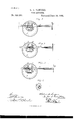
Figures 1., 2, and 3, horizontal sections through the base of the burner, showing the adjustingshaft in its various positions; Fig.
I 5 t, a perspective view of the wheel E, showing the hub constructed to form the clutch.
This invention relates to an im )rovement in the device employed in flat-wicked lamps for adjusting the elevation of the wick. In
wick-adjusters in which the two feedwheels are so united as to be turned simultaneously the wick is moved bodily, and if the wick be not cut parallel with the upper end of the wick-tube the higher projections of the wick will cause the flame to smoke, and if the wick be drawn down to prevent that smoking the extent of flame is reduced far below the capacity of the lamp.-
The object of my invention is to adjust 0 either edge of the wick independent of the other or the whole wick bodily, as may be required to bring the upper end of the wickinto its proper relation to the upper end of the wick-tube, to overcome defects in trimming or cutting the wick; and the invention consists in combining,with the wick-tube, a horizontal wick-adjuster shaft, in. the usual relalation to the wick-tube, with two wick-adjusting wheels loose on said shaft and working 0 through openings in the wick-tube, the said shaft and wheels constructed with elutclrconnections, whereby by a longitudinal movement of the shaft to one extreme both wheels will be clutched or engaged with the shaft and so 4 5 as to revolve with it, or,moved to the opposite extreme, one of the wheels only will be e11- gaged with the shaft, the other free, and at an intermediate longitudinal position of the shaft the other wheel will be engaged and the first free, and as more fully hereinafter described.
A represents the base of the burner B, the
(N0 model.)
wick-tube; C, the longitudinal wickznljuster shalt, arranged through the base in its usual relation to the wick-tube, but free for longi tudinal movement to acertain extent. D and 5 5 E are two wickadjuster wheelsof usual form, arranged loose upon the shaft C, and extending through slots a into the wicktuhe, so as to impinge upon the wick in the tube in the usual manner for adjusting wheels in lampburners. The shaft C is provided at its outer end with a head, F, by which the shalt may be rotated in the usual manner, and also by means of which the shaft may be drawn outward from theposition in Fl 1 to the extreme 6 5 position in Fig. 3, or returned, or moved to the intermediate position, as seen in Fig. 2. The wheel 1), which is the inner or most distant wheel from the head of the shaft, is constructed with a shoulder, b, on its face toward the head of the shaft, and is also pro Vided with a similar shoulder, (1, upon the opposite side. The wheel E is provided with a shoulder, 0, upon its side toward the head of the shaft. This shoulder @011 the wheel E is of greater length than the shoulder l) on the wheel D. These shoulders may bepins fixed in the wheels.
Into the shaft C a radially-preyecting stud, f, is arranged on the side of the wheel D cor- 8o responding to the shoulder b, and on the shaft C on the side of the wheel E corresponding to the shoulder e is a similar stud, h, and so that in the rotation of the shaft the said stud will engage the respective shoulders I) 0 and cause those wheels to revolve with the shaft. The shoulder a is longer than the shoulder b, and so that the shaft maybe drawn outward to the position seen in Fig. 2, so as to take the stud f so far from the wheel D that in rotation of 0 the shaft the stud f will not strike the shoulder 1), but the stud Jr will still engage the shoulder 6, as in Fig. 2. In that condition the retation of the shaft C will turn the wheel E, but leave the wheel D free, and so that the wick 5 will be acted upon only by the wheel E, and that edge of the wick will be adjusted without effect upon the wick at the opposite edge. On the shaft on the reverse side of the wheel D is a radial stud, 13, but so far distant from the stud it that it (the stud i) cannot engage the shoulder d on thewheel D until the shaft has been moved outward so far as to take the stud h out of reach of the shoulder e, as seen in Fig. 3; but when the shaft is drawn so far outward as to permit the stud h to escape the shoulder 6, then the stud i will engage the shoulder d on the wheel D, as indicated in Fig. 3, and in that position the rotation of the shaft 0 will be imparted to the wheel. D, leaving the wheel E free, and so that the wheel D will act upon the wick independent of the wheel E, and adjust that edge of the wick independent of the opposite edge of the wick. Therefore by' moving the shalt longitudinally to engage either or both wheels, as the case may be, the wick may be adjusted bodily, or either edge independent of the other.
The best method of forming the shoulders upon the wheels is to construct the wheel with a hub to embrace the shaft, and cut the shoulder in the hub, as seen in Fig. 4; but any suitable clutching device may be applied to the wheels to engage corresponding studs on the shaft, and so that the shaft at one extreme will clutch both wheels, at the other extreme will clutch but one of the wheels, and at an intermediate position will clutch the other wheel only.
It will be understood that the head F may be upon the opposite end of the shaft, as indicated in broken lines, Fig. 1. As here illustrated, it is. at the righthand end, and which is its usual position, and I have described the arrangement of the clutching mechanism with relation to the wheel in that position; but I do not wish to be understood as limiting my invention to such position, it only being essential that the shaft shall be free for longitudinal movement independent of the wheels, the shaft and wheels provided with a clutch mechanism by which at one extreme movement of the shaft both wheels are engaged, at the other extreme the one wheel only is engaged, and at the intermediate position the other wheel only is engaged.
I am aware that lamp-bu rners have been pro vided with two wheels arranged for an adj ustment independent of each other, and therefore do not claim, broadly, such a wick-adjusting device; but
WVhat I do claim is- 1. In alamp-burner, the combination of the Wiok-tube B, the horizontal shafts 0, parallel with the plane of the wick-tube, free for longitudinal movement and for rotation, the adj usting-wheels D E, arranged loose upon said shaft and extending through slots in the wick-tube, the said shaft and wheels constructed with clutch engagement, either wheel independent of the other or both together, such engagement being made under the longitudinal movement of the shaft, substantially as described.
2; The combinationof the wick-tube B, the horizontal shaft 0, parallel with the plane of the Wick-tube and free for longitudinal and rotative movement in the base of the burner, the two wheels D E, arranged loose upon said shaft and extending through slots in the wicktube, the wheel D, provided with a shoulder, b, on its inside, and with a shoulder, d, upon its outside, the wheel E, provided with a shoulder, 0, corresponding to the shoulder b on the wheel D and upon the same side of the wheel E, the said shoulder e of greater length than the shoulder b, the shaft provided with a stud, h, corresponding to the shoulder 0, with a stud, f, corresponding to the shoulder b, and with a stud, 2', corresponding to the shoulder 01, substantially as described, and whereby at one extreme longitudinal movement of the shaft O the two wheels will be engaged with the shaft, at the other extreme longitudinal movement but one wheel will be engaged with the shaft, leaving the other free, and at an intermediate position the other wheel only will be engaged, leaving the one wheel free.
HOPKINS A. SANFORD.
Publications (1)
| Publication Number | Publication Date |
|---|---|
| US320291A true US320291A (en) | 1885-06-16 |
Family
ID=2389432
Family Applications (1)
| Application Number | Title | Priority Date | Filing Date |
|---|---|---|---|
| US320291D Expired - Lifetime US320291A (en) | Half to james a |
Country Status (1)
| Country | Link |
|---|---|
| US (1) | US320291A (en) |
-
0
- US US320291D patent/US320291A/en not_active Expired - Lifetime
Similar Documents
| Publication | Publication Date | Title |
|---|---|---|
| US1244533A (en) | Shaft-coupling. | |
| US320291A (en) | Half to james a | |
| US677592A (en) | Clutch. | |
| US779055A (en) | Wick-raiser for oil-burners. | |
| US178029A (en) | Improvement in expansion-pulleys | |
| US354367A (en) | William h | |
| US557024A (en) | Xnumm | |
| US188418A (en) | Improvement in stove-pipe dampers | |
| US150579A (en) | Improvement in axles for vehicles | |
| US272687A (en) | William hayes | |
| US313678A (en) | Mabion a | |
| US266221A (en) | John sweeney | |
| US328417A (en) | Roller-skate | |
| US183581A (en) | Improvement in chimney-caps | |
| US314928A (en) | Wick-adjuster for oil-stoves | |
| US461929A (en) | Friction-clutch | |
| US409639A (en) | And james s | |
| US301842A (en) | Dayid c | |
| US133051A (en) | Improvement in vapor-burners | |
| US131449A (en) | Improvement in friction-pulleys | |
| US357545A (en) | Lewis j | |
| US327331A (en) | Sad-iron | |
| USRE14806E (en) | neville | |
| US644290A (en) | Power-transforming machine. | |
| US177241A (en) | Improvement in harvesters |