US3199130A - Shoe heating machines - Google Patents
Shoe heating machines Download PDFInfo
- Publication number
- US3199130A US3199130A US278058A US27805863A US3199130A US 3199130 A US3199130 A US 3199130A US 278058 A US278058 A US 278058A US 27805863 A US27805863 A US 27805863A US 3199130 A US3199130 A US 3199130A
- Authority
- US
- United States
- Prior art keywords
- fingers
- outsole
- heating
- shoe
- inoperative
- Prior art date
- Legal status (The legal status is an assumption and is not a legal conclusion. Google has not performed a legal analysis and makes no representation as to the accuracy of the status listed.)
- Expired - Lifetime
Links
Images


Classifications
-
- A—HUMAN NECESSITIES
- A43—FOOTWEAR
- A43D—MACHINES, TOOLS, EQUIPMENT OR METHODS FOR MANUFACTURING OR REPAIRING FOOTWEAR
- A43D25/00—Devices for gluing shoe parts
- A43D25/20—Arrangements for activating or for accelerating setting of adhesives, e.g. by using heat
Definitions
- the present invention relates to a novel apparatus for heating shoe parts and, more specifically, to a machine for heating an outsole and a shoe 'bottom prior to the attachment of an outsole thereto and activating, by the application of heat, adhesive which has been applied to an outsole thereby to .prepare the shoe bottom and outsole for adhesive joinder.
- One commercial process employed in the manufacture of shoes for attaching an outsole and a shoe bottom comprises forming a substantially solvent free ribbon of thermoplastic synthetic polymer resin adhesive by depositing the adhesive in molten condition upon marginal surface portions of the outsole and ⁇ cooling the ribbon to render it self-supporting, subsequently heating the ribbon and the portions of the outsole underlying it to restore the adhesive to molten condition and to prepare the underlying sole area for permanent adhesive attachment and concurrently heating the bottom portion of the shoe to which the outsole is to be attached.
- the shoe bottom and outsole are then brought together with the ribbon of molten adhesive between them and pressure applied to force the adhesive into permanent attaching relation with the heated surfaces of both the outsole and shoe bottom, the adhesive being then solidified by cooling.
- an object of the present invention is to provide a cement activating apparatus having means for automatically introducing a shoe outsole to a heating element in the apparatus and means for automatically extracting the outsole therefrom.
- a further object of this invention is the controlled correlation of the shoe upper and outsole exposure time.
- the end to lbe attained is the regulation of the interim of exposure of the outsole in accordance with the period of exposure of the shoe bottom such that each-of the members has the proper amount of heat transferred thereto and such that heating of the two members is completed simultaneously.
- a heating apparatus comprising heating means, mean-s for mounting a shoe bottom in position to be heated, means for supporting an outsole for exposure to ysaid heating means, ingress means Y for introducing the outsole to said heating means and egress means for extracting an outsole from exposure to said heating means.
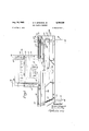
- FiG. l is a front View, partly in section, of a machine embodying the features of the invention.
- lFlG. 2 is a right side view of the machine illustrated in FiG. l, with a portion of the casing being broken away and parts shown in section;
- PEG. 3 is a view showing a control panel to be employed with the machine shown in FIG. l;
- FIG. 4 is a front View, partly in section, of the extractor mechanism located at the rear of the machine illustrated in PEG. l;
- FIG. 5 is an enlarged view showing a portion of the extractor mechanism shown in FIG. 4;
- FG. 6 is a detail view of the means for determining the terminal positions 4of the extractor means illustrated in FIG. 5;
- FlG. 7 is a view taken along the line VII-VII of FIG. 5 g
- FG. 8 is a top plan View of conveying means embodying the features of the subject invention.
- FlG. 9 is an electrical diagram.
- the frame of the machine comprises a lhollow base 10 supported on legs l2, FIGS. l and 2.
- the heating elements of the apparatus are mounted in a housing 14 secured to the upper portion of the base l@ and located above the midportion thereof.
- the relative positioning of the housing 14 with respect to the -base l@ is such as to facilitate the passage of an outsole therebetween in proximity to one of the heating elements whereby the outsole is subjected thereto.
- an outsole is introduced and extracted from exposure to one of the heating elements of the machine by conveyor means located 4in the base lil land a lasted shoe upper is receive-d in the upper portion of the housing 14 whereby the bottom thereof is conditioned by another of the heating elements of the machine.
- the housing 14 is divided into upper and lower chambers 16 and 1S respectively, by a dividing plate 2t), the upper chamber 16 having metal sheathed heating elements 22, 22 mounted therein for heating the bottom of a shoe upper positioned in the housing 14 and the lower chamber l having infrared module heating elements 24 mounted therein for heating an outsole conveyed in the base itl,
- the heating elements 22, 22 are mounted in an insulating wall 26 (FlG. 2) extending longitudinally across the rear of the upper chamber 16 thereby to provide a compartment 25 within the chamber 16 for the terminal contacts 27 of the heating elements 22, 22.
- Collars 23, 23 are employed to secure the heating elements 22, 22 in position in the wall 26 and angle members 3@ support the elements Z2, 22 in proper location.
- the ends of the heating elements 22, 22 remote from the wall 26 are bent upwardly to facilitate the heating of the heel portion of a shoe thereby to attain uniform heating of the shoe bottom.
- a shoe is held with its bottom in exposed relation to the heating elements 22, 22 by a toe rest 32 extending longitudinally across the central portion of the upper chamber and a heel rest 34 extending longitudinally across the forward portion thereof.
- the toe rest 32 and heel rest 34 comprise end plates 36, 38 and a plurality of rods lill, 42 extending therebetween, respectively, said side plates 36, 3d being secured to side walls 39, 39 of the chamber.
- the forward portion of the upper chamber is insulated by a wall d4.
- the lower chamber 1d has insulating walls 46, 4S on the front and rear sides thereof, the bottom of the chamber being open to facilitate the transfer of heat to an outsole.
- the heating elements 24- are suspended from a bracket Si? by angle members 52, 54, the bracket 5d being adjustably mounted in plates 58, 5S secured to the lower surface of the dividing plate and extending downwardly therefrom and transversely thereof.
- the plates 58, 5S and bracket 5i) are provided with a plurality of sets of tap holes 6i) cooperatively alined in the said members.
- the bracket 59 and, therefore, the heating elements 2d can thus be located in a variety of positions by the alinement of selected tapholes in the said members and the insertion of retaining studs 62 therethrough.
- the inner side walls 39, 39 of the housing are provided with vent holes 66 in the area of the lower chamberk 18.
- the sides of the housing are provided with outer insulating walls 68, 79 which define vent passages 72, 74 in cooperation with the inner side walls 39, 39.
- vent louvers are provided in the rear side wall.
- All of the inner surfaces of the upper and lower chambers 16 and 1S are plated with reflective aluminum to obtain maximum use of the heat generated by the heating elements.
- the base 10 has a plurality of wires Slt extending longitudinally in the upper portion thereof for supporting an outsole to be subjected to the heating elements 24.
- the support wires Sii extend through apertures 82 in a lateral end portion 84 of the base 1li, the terminal portion of the wires having arresting blocks S6 secured thereto which contact the outer face of the end portion 3d thereby to maintain the Wires in position, longitudinally across the base in immediate proximity to the heating elements 24, through apertures 83 in a lateral end portion 9i? opposite the end portion 34 and in alinement with the apertures 32 therein, and over a shaft 92.
- the terminal portion of the wires S0 remote from the arresting blocks 86 are secured to the base 1) by angle members 93 mounted thereon. Tension is maintained in the wires 80 by springs 94 interposed between the ends thereof and the angle member 93, as illustrated in FIG. 1.
- the springs 94 are essentially employed to compensate for expansion of the wires Si? resulting from exposure to the heating elements 24.
- r ⁇ he conveyor means comprises discrete apparatus for introducing an outsole to the heating elements 24 and for extracting the outsole therefrom, the apparatus being fundamentally identical with certain exceptions necessary to accomplish the distinct functions to be performed by the wo.
- the introducing apparatus 190 hereinafter referred to as the ingress means, is located in the front portion of the base 1t) and the'extracting apparatus 1412, hereinafter referred to as the egress means, is located in the rear portion thereof, as illustrated in FIGS. 2 and 8.
- the ingress means comprises a drive cylinder 194 and a piston housed therein having a drive rod 106 attached thereto and extending outwardly from the cylinder 1li-4.
- a feed arm carrier 108 is affixed to the end of the drive rod 106 remote from the cylinder 104, as shown in FIG. 1, the feed arm thus being movable in response to the movement of the aforesaid piston.
- the carrier 168 is guided for movement along a predetermined path by a shaft 112 along which ride spaced ears 110 projecting upwardly from the carrier.
- the shaft 112 is affixed to the base 10 by securing members 114 and 116 mounted on opposite ends thereof.
- the movement of the carrier 108 is additionally restricted by a guide roll 120 secured to the lower end of an L-shaped leg 122 affixed to the carrier 10S and slidable in a U-shaped track 124 mounted on the base 1li, extending therealong in parallel relation to the shaft 112.
- the co-operative action of the guide roll 12@ and track 124 prevents pivotal movement of the carrier 1h11 about the shaft 112.
- the carrier 193 has secured thereto a feed arm 139 extending rearwardly therefrom transversely to the wires 8? and thereunder.
- a plurality of spaced essentially L- shaped fingers 152 are secured to the arm 130 and extend upwardly therefrom between and above the wires S0, as illustrated in FiGS. 1, 2, and 8.
- an outsole to be heated is placed on the wires Sii between the fingers 132 and the housing 14 and pressure fluid is admitted to the right hand side of the cylinder 1114, as viewed in FIG. 1, thereby to drive the carrier 111 and, thus, the fingers 132 toward the housing 1d whereby the lingers 132 Contact the outsole and convey it into operative position under the heating elements 24.
- the operative terminal position of the carrier 103 and, therefore, the fingers 132 is determined by Contact of an L-shaped switch actuator 134 mounted on the leg 122 with a switch 131i mounted on the base 1@ in the midportion thereof, the terminal position being such as to place the outsole under the heating elements 24.
- the actuated switch 136 de-energizes a solenoid valve 133 (FlG. 9) which stops the introduction of pressure fluid to the right end of the cylinder 1&4 and initiates the introduction of pressure fluid to the left side thereof thereby to return the carrier 1% and fingers 132 to their normal inoperative positions.
- the egress means 162 comprises a drive cylinder 159, a drive rod 152, a feed arm carrier 154, ears 156, 156, a shaft 15S, securing members 161i and 162, a guide roll 164, an L-shaped leg 166, a U-shaped track 163, a switch actuator 170, and switch 172 all physically identical and functionally similar to the corresponding members in the ingress means 19t).
- the above referenced membersof the egress means 1112 are, however, reversed in relative location on the base 10, as compared to the corresponding members of the ingress means, 'since the ingress and egress means are initially located on opposite ends of the base 10, as best illustrated in FG. 8.
- the function of the egress means is the extraction of an outsole from exposure to the heating elements 24 and, accordingly, the components ofthe apparatus which contact the outsole and those immediately appurtenant thereto are physically and functionally distinct from the corresponding components of the ingress means, as hereinafter delineated.
- the carrier 154 has a boss 174, FIG. 7, mounted thereon extending inwardly therefrom having a bushing therein co-operatively alined with a bushing positioned in the carrier 154 for receiving a rotatable shaft 176.
- a rocker arm 17S having an upwardly projecting contact portion 181) is affixed to the shaft 176 adjacent the inward end of the boss 174.
- the rocker arm 17S has secured thereto a feed arm 182 extending forwardly therefrom transversely of the wires Si) and thereunder.
- a plurality of spaced essentially L- shaped fingers 184 are secured to the arm 132, ⁇ the fingers 134 being pivotal between an upper operative position between and above the wires and a lower inoperative position below the surface defined by the wires Sil, as hereinafter described.
- a positioning arm 136 is affixed to the terminal portion of the shaft 176 spaced from the rocker arm 178, the arm 136 being located on the opposite side of the carrier 154 from the arm 17S.
- the arm 186 extends toward the center of the apparatus along the rear of the carrier and has a stud 18S mounted on the end portion thereof between which and another stud 1913 located on the carrier 154 there is stretched a spring 192.
- the forces acting on the spring to cause pivotal movement of the arm 186, the shaft 176, the rocker arm 173 and, therefore, the fingers 184 are in equilibrium when the center line of the spring is alined with a diameter of the shaft 176 upon which the arm 186 is. mounted.
- the plate 19a pivots the rocker arm 186 clockwise when the contact portion 18) thereof contacts the plate 194, the arm 136 is thus rotated clockwise and, accordingly, the fingers 184 are pivoted downwardly into the lower inoperative positions.
- the plate 19d pivots the rocker arrn 136 counterclockwise when the contact portion 181) comes in contact therewith, the arm 186 thus being rotated counterclockwise and, therefore, the fingers 184i are pivoted upwardly into operative position.
- the rotative movement of the shaft 176 and, thus, the pivotal movement of the positioning arm 186 and rocher arm 178 is restricted by a stud 21H) secured to the shaft 176 and extending outwardly therefrom in a radial slot 262 in the boss 174.
- the Contact of the stud 26) with the opposite sides of the radial slot 2112 thus defines the operative and inoperative positions of the fingers 184.
- the spring 192 urges the stud 2G11 into contact with the appropriate side of the slot 292 and thereby retains the fingers in the defined positions when the rocker arm is withdrawn from Contact with the plate 194 or 1%.
- pressure iiuid is directed into the left end of the cylinder 1513, as viewed in FIG. 4, thereby to drive the carrier arm 154 and, thus, the lingers 134 toward the housing 14, the fingers being positioned in the lower inoperative positions below the Wires 80 as a result of the Contact of the portion 180 of the rocker arm 17S with the plate 154 and the retentive action of the spring 192 delined above.
- the fingers 184 are thus moved inwardly toward the center of the apparatus and pass under an outsole placed in exposed relation to the heating elements to a position beyond the outsole in location for extraction'thereof.
- the operative terminal position of the carrier 154 and, therefore, the fingers 134 is determined by contact of the switch actuator 17) with the switch 172, as defined above with respect to the ingress means.
- the fingers 184 When the fingers 184 have passed under the outsole and are located in position for extraction thereof, the fingers 134 are pivoted into operative position between and above the wires t) by contact of the portion 18@ of the rocker arm 178 with the plate 196 and are retained in said position by the spring 192 during the extraction stroke.
- the actuated switch 172 deenergizes a solenoid valve 21) which stops the introduction of pressure fluid into the left end of the cylinder and initiates the introduction of pressure fluid into the right end thereof thereby to extract the Outsole from the heating elements.
- the fingers 184 When the carrier 154 reaches its inoperative terminal position, the fingers 184 are pivoted downwardly into the lower inoperative position by the co-operative action of the plate 194 and the rocker arm 173 and retained therein as defined above.
- the heating elements 22, 22 and 24 are controlled by relays CR1, CR2, CRS', and CR4, CRS, respectively, and the solenoids 133 and 211) by timers TR1 and TR2, respectively.
- Power is supplied to the three-phase circuit illustrated in FIG. 9 through leads L1, L2 and L3 connected to a power supply 212.
- the voltage supplied by the power supply 212 is diminished by a transformer T1 to facilitate the use of the electrical circuitry to be hereinafter described.
- the control relays CR1, CK2 and CRS are controlled by a percentage timer HC1 and the control relays CR4 and CRS by a percentage timer HC2, said timers being identical.
- the timers HC1 and HG2 can be adjusted to regulate the period of timev the heaters are on during the time the shoe bottom and outsole are exposed thereto thereby to control the level of heat generated and ensure that the articlesare completely heated but not overheated or burned.
- the timers HC1 and HCZ comprise motors M and switches 22), the motors M controlling the switches 220 in accordance with the time increments set on the control panel, as defined above.
- the heaters 22, 22, and 24 are thus turned on and off a given percentage of the period of operation.
- the percentage timer circuit is open and closed by a switch 222. It is to be understood that any convenient means for independently controlling the heaters 22, 22, and 24 may be employed, the above merely being a preferred means.
- the solenoid 138 and, therefore, the ingress means 16) is controlled by the timer TR1.
- the timer TR1 is utilized to determine the time at which the ingress means introduces an outsole to the heating element 24. That is, the timer TR1 can be adjusted to energize the solenoid 138 a given time after a switch 224 is closed thereby initiating the introduction of pres- ⁇ sure iiuid into the cylinder 104 and movement of the carrier 163 and finger 132 at the precise time desired.
- the exact time delay selected is determined by the cycle of operation established by the operator and the relative heating requirements of the shoe bottom and ⁇ outsole.
- the switch 226 When the selectedtime delay has elapsed, the switch 226 is closed and the solenoid 138 energized and the switch 228 is closed and the heating timer TR2 energized. At the terminus of the ingress movement, the switch is shifted by the actuator 134, the circuit to the timer TR1 is interrupted, and the timer TR2 is actuated.
- the timer TR2 is employed to regulate the period ⁇ of time which the outsole is exposed to the heating elements 24.
- the switch 23) is closed and the solenoid 210 energized whereby pressure fluid is introduced into the cylinder and the fingers 184 moved into operative location, the switch 232 also being shifted at this time.
- the switch 172 is opened, the solenoid 21) de-energized, the holding circuit for TR2 deactivated and the fingers retracted.
- the operator can thus provide sufdcient time to complete additional tasks during the heating cycle, ensure that the outsole and shoe bottom have the proper amount of heat transferred theretoand provide for the simultaneous completion of the shoe bottom and the outsole. regulated by the adjustment of the controls 234y and 235 on the control panel 218.
- the various time elements dened above are initially selected and recorded on the control panel 213, the shoe bottom is placed in position and the outsole placed on the wires 80 in the location delineated above.
- the operation of the machine is thereafter automatic and the operator is free to perform other tasks required of him.
- the shoe bottom is exposed to the heating elements 22, 22 immediately upon being locatedv in position.
- the outsole is introduced .and extracted from the heating elements 24 At the'.
- the timers TR1 and TR2 can beY end of the operation cycle, the operator must remove the simultaneously completed articles and repeat the operation.
- a heating apparatus for heating a shoe bottom and an outsole and for activating adhesive on said outsole comprising heating means, means for mounting a lasted shoe with its bottom in position to be heated, means for supporting an outsole for exposure to said heating means comprising a plurality of spatially arranged parallel wires, ingress means for introducing an outsole to said heating means comprising a plurality of fingers extending between ⁇ and above ⁇ said wires and means for moving said fingers between an inoperative and an operative position, and egress means for extracting an outsole from exposure to said heating means comprising a second plurality of fingers pivotal between an upper position between and above said wires and a lower position below a surface defined by said wires, means for pivoting said second fingers into said upper position when said second fingers are in position to extract an outsole and for pivoting said second fingers into said lower position when said second fingers are located in an inoperative position, and-means for moving said second fingers between said inoperativerposition and an operative position,
- a heating apparatus Ifor heating a shoe part and activating adhesive thereon comprising heating means, means for supporting the shoe part for movement into and out of a heat receiving position, said support means comprising a plurality of spatially arranged parallel wires, ingress means for introducing a shoe part to said heating means comprising a plurality of fingers extending between and above said wires, mean-s for movingsaid fingers between an inoperative and an operative position and means for effecting the return of said fingers to the inoperative position, and egress means for extracting a shoe part from exposure to said heating means comprising a second plurality of fingers pivotal between an upper position between and above said wires and a lower posi- Ition below a surface defined by said w-ires, means ⁇ for locating said second fingers in said upper position when said second fingers are in position to extract a shoe part, means for locating said second fingers in said lower position when -the extraction of an outsole has been completed, means for retaining said second fingers in the defined upper and lower positions upon withdrawal from one of said support
- a heating apparatus for heating a shoe part and activating adhesive thereon comprising heating means, means for supporting a shoe part for exposure to said heating means comprising a plurality of discrete parallel members, ingress means for introducing a shoe part to said heating means comprising a plurality of lingers extending between and above said parallel members, means for moving said fingers between an inoperative and an operative position, and means for effecting the return of said fingers to the inoperative position, egress means for extracting ⁇ a shoe part from exposure to said heating means comprising a second plurality of fingers movable between an upper position between and above said parallel members and a lower position below a surface defined by said parallel members, means for moving said second fingers into said upper position when said second fingers are in position to extract a shoe part and for moving said second ngers into said lower position when said second fingers are located in an inoperative position, means for retaining said second fingers in the defined positions, means for moving said second fingers between said inoperative position and an operative position, means for regulating the movement of said second fingers between said inoperative
- a heating apparatus for heating a shoe bottom and an outsole and for activ-ating adhesive on said outsole comprising heating means, means for mounting a lasted shoe with its bottom in position to be heated, means for supporting an outsole for exposure to said heating means comprising a plurality of discrete parallel members, ingress means for introducing an outsole to said heating means comprising a plurality of fingers extending between and above said parallel members, means for moving said fingers 'between an inoperative and an operative position, and means for effecting the return of said fingers Lo the inoperative position, and egress means for extracting an outsole from exposure to said heating means comprising a second plurality Iof fingers movable between an upper position between and above said parallel members and a lower position below a surface defined by said parallel members, means for moving said second fingers into said upper position w en said second fingers are in position to extract an outsole and for moving said second fingers into said lower position when said second fingers are located in an inoperative position, means for retaining said second fingers in the defined upper and lower positions, means for moving
- a heating apparatus for heating a shoe bott-om and an outsole and for activa-ting adhesive on said outsole comprising heating means, means for mounting a shoe with its bottom in position to be heated, means for sup ⁇ porting an outsole for movement into and out of a heat receiving position, said support means comprising a plurality of spatially arranged parallel members, ingress means for introducing an outsole to said heating means comprising a plurality of fingers extending between ⁇ and above said parallel members, means for moving said ngers between an inoperative and an operative position, means for automatically controlling the movement of said fingers thereby to facilitate correlation of the introduction lof a shoe bot-tom and lan outsole, Iand means for effecting the return oi said fingers to the inoperative position, and egress means for extracting an outsole from exposure to said heating means comprising a second plurality of fingers movable between an upper position between ⁇ and above said parallel members and a lower position below a surface defined lby said parallel members, means for moving said second fingers into said
- a heating apparatus for heating a shoe bottom and an outsole and for activating adhesive on said outsole comprising heating means, means for mounting a shoe with its bottom in position to be heated, means f-or supporting an outsole for exposure to said heating means comprising a plurality of discrete parallel members, ingress means for introducing an outsole to said heating means comprising a plurality of ngers extending between and above said parallel members, means vfor moving said fingers between an inoperative and an operative position, and means Afor effecting the return of said fingers to the inoperative position, and egress means lfor extracting an youtsole from exposure to said heating means cornprising -a second plurality of fingers movable between an upper position between and above said parallel members and a lower position below a surface defined by said parallel members, means for moving said second fingers into said upper position when said second fingers are in position to extract an outsole and for moving said ysecond fingers into said lower position when said second fingers are located in an inoperative position, mean-s for retaining said second fingers lin the
- a heating apparatus for heating a shoe bottom and an outsole and for activating adhesive on said outsole comprising heating means, means for mounting a shoe with its bottom in position to be heated, means -for supporting an outsole for movement into and out of a heat receiving position, said support means comprising a plurality of spatially arranged parallel members, ingress means for introducing an outsole to said heating means comprising a plurality lof fingers extending between and above said parallel members, means for moving lsaid fingers between an inoperative and an operative position, means for automatically controlling the Vmovement of said lingers thereby to facilitate correlation of the introduction of a shoe bottom and an outsole, and means for eecting the return of said ingers lil to the inoperative position, and egress means for extracting an outsole from exposure to said heating means comprising a second plurality of fingers movable between an upper position between and above said parallel members and a lower position below a surface defined 'by said parallel members, means for moving said second fingers into said upper position when
Description
Aug. l0, 1965 G. v. sPRAGUE, JR
SHOE HEATING MACHINES 5 Sheets-Sheet 1 Filed May 6, 1963 eJr:
Uu 6 wm arm UA n.6 ,mm
aUu @B Aug. 10, 1965 G. v. sPRAGuE, JR
SHOE HEATING MACHINES Filed May 6, 1963 5 Sheets-Sheet 2:
Aug. 10, 1965 s. v. sPRAGUE, JR
SHOE HEATING MACHINES 5 Sheets-Sheet 3 Filed May 6, 1963 Aug- 10, 1965 G. v. sPRAGuE, JR 3,199,130
SHOE HEATING MACHINES Filed May 6, 1963 5 Sheets-Sheet 4 Z0 Egg. @e
r 1 L la! :l I: H H if g H LJ U El U H a0 e H tl a@ f 13e 108 my; l I 110'4 L' U 1 Aug- 10, 1965 G. v. SPRAGUE, JR 3,199,130
SHOE HEATING MACHINES Filed May 6, 1963 5 Sheets-Sheet 5 L @R4 Tem cme T crea @R5 United States Patent O 3,199,130 SHQE HEATENG MACHINES Gordon V. Sprague, Jr., Danvers, Mass., assigner to United Shoe Machinery Corporation, Boston, Mass., and Flemington, NJ., a corporation of New .lersey Filed May 6, 1963, Ser. No. 278,058 7 Claims. (Cl. 12-4.1)
The present invention relates to a novel apparatus for heating shoe parts and, more specifically, to a machine for heating an outsole and a shoe 'bottom prior to the attachment of an outsole thereto and activating, by the application of heat, adhesive which has been applied to an outsole thereby to .prepare the shoe bottom and outsole for adhesive joinder.
One commercial process employed in the manufacture of shoes for attaching an outsole and a shoe bottom comprises forming a substantially solvent free ribbon of thermoplastic synthetic polymer resin adhesive by depositing the adhesive in molten condition upon marginal surface portions of the outsole and `cooling the ribbon to render it self-supporting, subsequently heating the ribbon and the portions of the outsole underlying it to restore the adhesive to molten condition and to prepare the underlying sole area for permanent adhesive attachment and concurrently heating the bottom portion of the shoe to which the outsole is to be attached. The shoe bottom and outsole are then brought together with the ribbon of molten adhesive between them and pressure applied to force the adhesive into permanent attaching relation with the heated surfaces of both the outsole and shoe bottom, the adhesive being then solidified by cooling. A more detailed analysis of the above process is delineated in application for United States Letters Patent, Serial No. 121,118, filed June 30, 1961, in the name of Conrad Rossitto. The present invention is concerned with apparatus for activating or heating the adhesive ribbon to restore it to molten condition and heating the outsole and shoe bot- Om.'
Heretofore, in machines utilized for this purpose an operator was required manually to introduce both the outsole and the shoe bottom to the heating elements of the machine. This was normally accomplished by placing an outsole in a receptacle and physically moving the receptable into a position where the outsole was expos-ed to the heating elements. This was not only physically taxing on the operator but also time consuming. The operator was additionally required to position the shoe upper in location on the machine whereby the bottom thereof was subject to the heating means. The result of requiring an operator to perform the plurality of tasks stated above was an inability consistently to attain continuity in the amount of heat transferred to the two members and, therefore the cement. The consequence of such lack of continuity was an inconsistency in the quality of adhesive bonds produced. The operator was also commonly concurrently required physically to press the shoe bottom and upper into adhesive contact, thus, further reducing his effectiveness and eliiciency,
Accordingly, an object of the present invention is to provide a cement activating apparatus having means for automatically introducing a shoe outsole to a heating element in the apparatus and means for automatically extracting the outsole therefrom.
A further object of this invention is the controlled correlation of the shoe upper and outsole exposure time. The end to lbe attained is the regulation of the interim of exposure of the outsole in accordance with the period of exposure of the shoe bottom such that each-of the members has the proper amount of heat transferred thereto and such that heating of the two members is completed simultaneously.
g 3,199,130 Patented Aug. l0, 1965 ICC To this end and in accordance with a feature of the present invention, there is provi-ded a heating apparatus comprising heating means, mean-s for mounting a shoe bottom in position to be heated, means for supporting an outsole for exposure to ysaid heating means, ingress means Y for introducing the outsole to said heating means and egress means for extracting an outsole from exposure to said heating means.
The `above and other features of the invention will now be described, the accompanying drawings being included to aid in the understanding thereof.
in the drawings:
FiG. l is a front View, partly in section, of a machine embodying the features of the invention;
lFlG. 2 is a right side view of the machine illustrated in FiG. l, with a portion of the casing being broken away and parts shown in section;
PEG. 3 is a view showing a control panel to be employed with the machine shown in FIG. l;
FIG. 4 is a front View, partly in section, of the extractor mechanism located at the rear of the machine illustrated in PEG. l;
FIG. 5 is an enlarged view showing a portion of the extractor mechanism shown in FIG. 4;
FG. 6 is a detail view of the means for determining the terminal positions 4of the extractor means illustrated in FIG. 5;
FlG. 7 is a view taken along the line VII-VII of FIG. 5 g
FG. 8 is a top plan View of conveying means embodying the features of the subject invention; and,
FlG. 9 is an electrical diagram.
The frame of the machine comprises a lhollow base 10 supported on legs l2, FIGS. l and 2. The heating elements of the apparatus, as hereinafter defined, are mounted in a housing 14 secured to the upper portion of the base l@ and located above the midportion thereof. The relative positioning of the housing 14 with respect to the -base l@ is such as to facilitate the passage of an outsole therebetween in proximity to one of the heating elements whereby the outsole is subjected thereto. As hereinafter described, an outsole is introduced and extracted from exposure to one of the heating elements of the machine by conveyor means located 4in the base lil land a lasted shoe upper is receive-d in the upper portion of the housing 14 whereby the bottom thereof is conditioned by another of the heating elements of the machine.
The housing 14 is divided into upper and lower chambers 16 and 1S respectively, by a dividing plate 2t), the upper chamber 16 having metal sheathed heating elements 22, 22 mounted therein for heating the bottom of a shoe upper positioned in the housing 14 and the lower chamber l having infrared module heating elements 24 mounted therein for heating an outsole conveyed in the base itl, The heating elements 22, 22 are mounted in an insulating wall 26 (FlG. 2) extending longitudinally across the rear of the upper chamber 16 thereby to provide a compartment 25 within the chamber 16 for the terminal contacts 27 of the heating elements 22, 22. Collars 23, 23 are employed to secure the heating elements 22, 22 in position in the wall 26 and angle members 3@ support the elements Z2, 22 in proper location. The ends of the heating elements 22, 22 remote from the wall 26 are bent upwardly to facilitate the heating of the heel portion of a shoe thereby to attain uniform heating of the shoe bottom. A shoe is held with its bottom in exposed relation to the heating elements 22, 22 by a toe rest 32 extending longitudinally across the central portion of the upper chamber and a heel rest 34 extending longitudinally across the forward portion thereof. The toe rest 32 and heel rest 34 comprise end plates 36, 38 and a plurality of rods lill, 42 extending therebetween, respectively, said side plates 36, 3d being secured to side walls 39, 39 of the chamber. The forward portion of the upper chamber is insulated by a wall d4.
The lower chamber 1d has insulating walls 46, 4S on the front and rear sides thereof, the bottom of the chamber being open to facilitate the transfer of heat to an outsole. The heating elements 24- are suspended from a bracket Si? by angle members 52, 54, the bracket 5d being adjustably mounted in plates 58, 5S secured to the lower surface of the dividing plate and extending downwardly therefrom and transversely thereof. The plates 58, 5S and bracket 5i) are provided with a plurality of sets of tap holes 6i) cooperatively alined in the said members. The bracket 59 and, therefore, the heating elements 2d can thus be located in a variety of positions by the alinement of selected tapholes in the said members and the insertion of retaining studs 62 therethrough. The inner side walls 39, 39 of the housing are provided with vent holes 66 in the area of the lower chamberk 18. The sides of the housing are provided with outer insulating walls 68, 79 which define vent passages 72, 74 in cooperation with the inner side walls 39, 39. As illustrated in FIG. 2, vent louvers are provided in the rear side wall.
All of the inner surfaces of the upper and lower chambers 16 and 1S are plated with reflective aluminum to obtain maximum use of the heat generated by the heating elements. f
As illustrated in FIGS. 1, 2 and particularly 8, the base 10 has a plurality of wires Slt extending longitudinally in the upper portion thereof for supporting an outsole to be subiected to the heating elements 24. The support wires Sii extend through apertures 82 in a lateral end portion 84 of the base 1li, the terminal portion of the wires having arresting blocks S6 secured thereto which contact the outer face of the end portion 3d thereby to maintain the Wires in position, longitudinally across the base in immediate proximity to the heating elements 24, through apertures 83 in a lateral end portion 9i? opposite the end portion 34 and in alinement with the apertures 32 therein, and over a shaft 92. The terminal portion of the wires S0 remote from the arresting blocks 86 are secured to the base 1) by angle members 93 mounted thereon. Tension is maintained in the wires 80 by springs 94 interposed between the ends thereof and the angle member 93, as illustrated in FIG. 1. The springs 94 are essentially employed to compensate for expansion of the wires Si? resulting from exposure to the heating elements 24.
r`he conveyor means comprises discrete apparatus for introducing an outsole to the heating elements 24 and for extracting the outsole therefrom, the apparatus being fundamentally identical with certain exceptions necessary to accomplish the distinct functions to be performed by the wo. The introducing apparatus 190, hereinafter referred to as the ingress means, is located in the front portion of the base 1t) and the'extracting apparatus 1412, hereinafter referred to as the egress means, is located in the rear portion thereof, as illustrated in FIGS. 2 and 8.
The ingress means comprises a drive cylinder 194 and a piston housed therein having a drive rod 106 attached thereto and extending outwardly from the cylinder 1li-4. A feed arm carrier 108 is affixed to the end of the drive rod 106 remote from the cylinder 104, as shown in FIG. 1, the feed arm thus being movable in response to the movement of the aforesaid piston. The carrier 168 is guided for movement along a predetermined path by a shaft 112 along which ride spaced ears 110 projecting upwardly from the carrier. The shaft 112 is affixed to the base 10 by securing members 114 and 116 mounted on opposite ends thereof. The movement of the carrier 108 is additionally restricted by a guide roll 120 secured to the lower end of an L-shaped leg 122 affixed to the carrier 10S and slidable in a U-shaped track 124 mounted on the base 1li, extending therealong in parallel relation to the shaft 112. The co-operative action of the guide roll 12@ and track 124 prevents pivotal movement of the carrier 1h11 about the shaft 112.
The carrier 193 has secured thereto a feed arm 139 extending rearwardly therefrom transversely to the wires 8? and thereunder. A plurality of spaced essentially L- shaped fingers 152 are secured to the arm 130 and extend upwardly therefrom between and above the wires S0, as illustrated in FiGS. 1, 2, and 8. In the operation of the ingress means 161i, an outsole to be heated is placed on the wires Sii between the fingers 132 and the housing 14 and pressure fluid is admitted to the right hand side of the cylinder 1114, as viewed in FIG. 1, thereby to drive the carrier 111 and, thus, the fingers 132 toward the housing 1d whereby the lingers 132 Contact the outsole and convey it into operative position under the heating elements 24. rThe operative terminal position of the carrier 103 and, therefore, the fingers 132 is determined by Contact of an L-shaped switch actuator 134 mounted on the leg 122 with a switch 131i mounted on the base 1@ in the midportion thereof, the terminal position being such as to place the outsole under the heating elements 24. The actuated switch 136 de-energizes a solenoid valve 133 (FlG. 9) which stops the introduction of pressure fluid to the right end of the cylinder 1&4 and initiates the introduction of pressure fluid to the left side thereof thereby to return the carrier 1% and fingers 132 to their normal inoperative positions.
As illustrated in FIGS. 2, 4, and S, the egress means 162 comprises a drive cylinder 159, a drive rod 152, a feed arm carrier 154, ears 156, 156, a shaft 15S, securing members 161i and 162, a guide roll 164, an L-shaped leg 166, a U-shaped track 163, a switch actuator 170, and switch 172 all physically identical and functionally similar to the corresponding members in the ingress means 19t). The above referenced membersof the egress means 1112 are, however, reversed in relative location on the base 10, as compared to the corresponding members of the ingress means, 'since the ingress and egress means are initially located on opposite ends of the base 10, as best illustrated in FG. 8.
As stated above, the function of the egress means is the extraction of an outsole from exposure to the heating elements 24 and, accordingly, the components ofthe apparatus which contact the outsole and those immediately appurtenant thereto are physically and functionally distinct from the corresponding components of the ingress means, as hereinafter delineated. The carrier 154 has a boss 174, FIG. 7, mounted thereon extending inwardly therefrom having a bushing therein co-operatively alined with a bushing positioned in the carrier 154 for receiving a rotatable shaft 176. A rocker arm 17S having an upwardly projecting contact portion 181) is affixed to the shaft 176 adjacent the inward end of the boss 174. The rocker arm 17S has secured thereto a feed arm 182 extending forwardly therefrom transversely of the wires Si) and thereunder. A plurality of spaced essentially L- shaped fingers 184 are secured to the arm 132, `the fingers 134 being pivotal between an upper operative position between and above the wires and a lower inoperative position below the surface defined by the wires Sil, as hereinafter described.
As illustrated in FIGS. 5 and 7, a positioning arm 136 is affixed to the terminal portion of the shaft 176 spaced from the rocker arm 178, the arm 136 being located on the opposite side of the carrier 154 from the arm 17S. The arm 186 extends toward the center of the apparatus along the rear of the carrier and has a stud 18S mounted on the end portion thereof between which and another stud 1913 located on the carrier 154 there is stretched a spring 192. The forces acting on the spring to cause pivotal movement of the arm 186, the shaft 176, the rocker arm 173 and, therefore, the fingers 184 are in equilibrium when the center line of the spring is alined with a diameter of the shaft 176 upon which the arm 186 is. mounted. Accordingly, when the end of the spring 122 affixed to the stud 183 is urged downwardly, a component of the `force exerted by the spring 192 upon the arm 186 would impart clockwise rotation to the arm 186 and, conversely, when the stud 183 is urged upwardly, 'counterclockwise rotation would be imparted to the arm 126. Rocker arm positioner plates 194, 1% secured to the frame in spaced relationship are employed to pivot the rocker arm 173 and, therefore, the positioning arm 126 thereby to position the spring on either side of the above defined equilibrium position. The plate 19a pivots the rocker arm 186 clockwise when the contact portion 18) thereof contacts the plate 194, the arm 136 is thus rotated clockwise and, accordingly, the fingers 184 are pivoted downwardly into the lower inoperative positions. The plate 19d pivots the rocker arrn 136 counterclockwise when the contact portion 181) comes in contact therewith, the arm 186 thus being rotated counterclockwise and, therefore, the fingers 184i are pivoted upwardly into operative position. The rotative movement of the shaft 176 and, thus, the pivotal movement of the positioning arm 186 and rocher arm 178 is restricted by a stud 21H) secured to the shaft 176 and extending outwardly therefrom in a radial slot 262 in the boss 174. The Contact of the stud 26) with the opposite sides of the radial slot 2112 thus defines the operative and inoperative positions of the fingers 184. When the rocker arm 173 contacts the plate 194 or 1% and the positioning arm is moved to either side of the equilibrium position of the spring 192, the spring 192 urges the stud 2G11 into contact with the appropriate side of the slot 292 and thereby retains the fingers in the defined positions when the rocker arm is withdrawn from Contact with the plate 194 or 1%.
In the operation of the egress means N2, pressure iiuid is directed into the left end of the cylinder 1513, as viewed in FIG. 4, thereby to drive the carrier arm 154 and, thus, the lingers 134 toward the housing 14, the fingers being positioned in the lower inoperative positions below the Wires 80 as a result of the Contact of the portion 180 of the rocker arm 17S with the plate 154 and the retentive action of the spring 192 delined above. The fingers 184 are thus moved inwardly toward the center of the apparatus and pass under an outsole placed in exposed relation to the heating elements to a position beyond the outsole in location for extraction'thereof. The operative terminal position of the carrier 154 and, therefore, the fingers 134 is determined by contact of the switch actuator 17) with the switch 172, as defined above with respect to the ingress means. When the fingers 184 have passed under the outsole and are located in position for extraction thereof, the fingers 134 are pivoted into operative position between and above the wires t) by contact of the portion 18@ of the rocker arm 178 with the plate 196 and are retained in said position by the spring 192 during the extraction stroke. The actuated switch 172 deenergizes a solenoid valve 21) which stops the introduction of pressure fluid into the left end of the cylinder and initiates the introduction of pressure fluid into the right end thereof thereby to extract the Outsole from the heating elements. When the carrier 154 reaches its inoperative terminal position, the fingers 184 are pivoted downwardly into the lower inoperative position by the co-operative action of the plate 194 and the rocker arm 173 and retained therein as defined above.
As illustrated in FIG. 9, the heating elements 22, 22 and 24 are controlled by relays CR1, CR2, CRS', and CR4, CRS, respectively, and the solenoids 133 and 211) by timers TR1 and TR2, respectively. Power is supplied to the three-phase circuit illustrated in FIG. 9 through leads L1, L2 and L3 connected to a power supply 212. The voltage supplied by the power supply 212 is diminished by a transformer T1 to facilitate the use of the electrical circuitry to be hereinafter described.
The control relays CR1, CK2 and CRS are controlled by a percentage timer HC1 and the control relays CR4 and CRS by a percentage timer HC2, said timers being identical. The timers HC1 and HG2 can be adjusted to regulate the period of timev the heaters are on during the time the shoe bottom and outsole are exposed thereto thereby to control the level of heat generated and ensure that the articlesare completely heated but not overheated or burned. When an operator has established the period of time he requires to attach a shoe bottom and outsole and/or any other required tasks, he can adjust the timers HC1 and HCZ by adjustment of control knobs 214, 216, respectively, on a control panel 218 and thus regulate the level of heat generated by the respective heaters in accordance with the period of exposure thereby ensuring that the proper amount of heat will be transferred to the shoe bottom and outsole during the cycle of operation established by the operator.
The timers HC1 and HCZ comprise motors M and switches 22), the motors M controlling the switches 220 in accordance with the time increments set on the control panel, as defined above. The heaters 22, 22, and 24 are thus turned on and off a given percentage of the period of operation. The percentage timer circuit is open and closed by a switch 222. It is to be understood that any convenient means for independently controlling the heaters 22, 22, and 24 may be employed, the above merely being a preferred means.
As stated above, the solenoid 138 and, therefore, the ingress means 16) is controlled by the timer TR1. The timer TR1 is utilized to determine the time at which the ingress means introduces an outsole to the heating element 24. That is, the timer TR1 can be adjusted to energize the solenoid 138 a given time after a switch 224 is closed thereby initiating the introduction of pres-` sure iiuid into the cylinder 104 and movement of the carrier 163 and finger 132 at the precise time desired. The exact time delay selected is determined by the cycle of operation established by the operator and the relative heating requirements of the shoe bottom and` outsole. When the selectedtime delay has elapsed, the switch 226 is closed and the solenoid 138 energized and the switch 228 is closed and the heating timer TR2 energized. At the terminus of the ingress movement, the switch is shifted by the actuator 134, the circuit to the timer TR1 is interrupted, and the timer TR2 is actuated.
The timer TR2 is employed to regulate the period` of time which the outsole is exposed to the heating elements 24. When the selected time has transpired, the switch 23) is closed and the solenoid 210 energized whereby pressure fluid is introduced into the cylinder and the fingers 184 moved into operative location, the switch 232 also being shifted at this time. At the operative position, the switch 172 is opened, the solenoid 21) de-energized, the holding circuit for TR2 deactivated and the fingers retracted. The operator can thus provide sufdcient time to complete additional tasks during the heating cycle, ensure that the outsole and shoe bottom have the proper amount of heat transferred theretoand provide for the simultaneous completion of the shoe bottom and the outsole. regulated by the adjustment of the controls 234y and 235 on the control panel 218.
In the operation of the machine the various time elements dened above are initially selected and recorded on the control panel 213, the shoe bottom is placed in position and the outsole placed on the wires 80 in the location delineated above. The operation of the machine is thereafter automatic and the operator is free to perform other tasks required of him. The shoe bottom is exposed to the heating elements 22, 22 immediately upon being locatedv in position. The outsole is introduced .and extracted from the heating elements 24 At the'.
The timers TR1 and TR2 can beY end of the operation cycle, the operator must remove the simultaneously completed articles and repeat the operation.
Having thus described my invention, what I claim as new and desire to secure by Letters Patent of the United States is:
1. A heating apparatus for heating a shoe bottom and an outsole and for activating adhesive on said outsole comprising heating means, means for mounting a lasted shoe with its bottom in position to be heated, means for supporting an outsole for exposure to said heating means comprising a plurality of spatially arranged parallel wires, ingress means for introducing an outsole to said heating means comprising a plurality of fingers extending between `and above `said wires and means for moving said fingers between an inoperative and an operative position, and egress means for extracting an outsole from exposure to said heating means comprising a second plurality of fingers pivotal between an upper position between and above said wires and a lower position below a surface defined by said wires, means for pivoting said second fingers into said upper position when said second fingers are in position to extract an outsole and for pivoting said second fingers into said lower position when said second fingers are located in an inoperative position, and-means for moving said second fingers between said inoperativerposition and an operative position,
2. A heating apparatus Ifor heating a shoe part and activating adhesive thereon comprising heating means, means for supporting the shoe part for movement into and out of a heat receiving position, said support means comprising a plurality of spatially arranged parallel wires, ingress means for introducing a shoe part to said heating means comprising a plurality of fingers extending between and above said wires, mean-s for movingsaid fingers between an inoperative and an operative position and means for effecting the return of said fingers to the inoperative position, and egress means for extracting a shoe part from exposure to said heating means comprising a second plurality of fingers pivotal between an upper position between and above said wires and a lower posi- Ition below a surface defined by said w-ires, means `for locating said second fingers in said upper position when said second fingers are in position to extract a shoe part, means for locating said second fingers in said lower position when -the extraction of an outsole has been completed, means for retaining said second fingers in the defined upper and lower positions upon withdrawal from one of said locating means, and means for moving said second fingers between an inoperative position and an operative position.
3. A heating apparatus for heating a shoe part and activating adhesive thereon comprising heating means, means for supporting a shoe part for exposure to said heating means comprising a plurality of discrete parallel members, ingress means for introducing a shoe part to said heating means comprising a plurality of lingers extending between and above said parallel members, means for moving said fingers between an inoperative and an operative position, and means for effecting the return of said fingers to the inoperative position, egress means for extracting `a shoe part from exposure to said heating means comprising a second plurality of fingers movable between an upper position between and above said parallel members and a lower position below a surface defined by said parallel members, means for moving said second fingers into said upper position when said second fingers are in position to extract a shoe part and for moving said second ngers into said lower position when said second fingers are located in an inoperative position, means for retaining said second fingers in the defined positions, means for moving said second fingers between said inoperative position and an operative position, means for regulating the movement of said second fingers between said inoperative position and said operative position to control the period of exposure of the shoe part, and means for effecting the return of said second fingers to the inoperative position thereby to extract said shoe part.
d. A heating apparatus for heating a shoe bottom and an outsole and for activ-ating adhesive on said outsole comprising heating means, means for mounting a lasted shoe with its bottom in position to be heated, means for supporting an outsole for exposure to said heating means comprising a plurality of discrete parallel members, ingress means for introducing an outsole to said heating means comprising a plurality of fingers extending between and above said parallel members, means for moving said fingers 'between an inoperative and an operative position, and means for effecting the return of said fingers Lo the inoperative position, and egress means for extracting an outsole from exposure to said heating means comprising a second plurality Iof fingers movable between an upper position between and above said parallel members and a lower position below a surface defined by said parallel members, means for moving said second fingers into said upper position w en said second fingers are in position to extract an outsole and for moving said second fingers into said lower position when said second fingers are located in an inoperative position, means for retaining said second fingers in the defined upper and lower positions, means for moving said second fingers between said inoperative position and an operative position, and means for effecting the return of said second fingers to the inoperative position thereby to extract an outsole.
5. A heating apparatus for heating a shoe bott-om and an outsole and for activa-ting adhesive on said outsole comprising heating means, means for mounting a shoe with its bottom in position to be heated, means for sup` porting an outsole for movement into and out of a heat receiving position, said support means comprising a plurality of spatially arranged parallel members, ingress means for introducing an outsole to said heating means comprising a plurality of fingers extending between` and above said parallel members, means for moving said ngers between an inoperative and an operative position, means for automatically controlling the movement of said fingers thereby to facilitate correlation of the introduction lof a shoe bot-tom and lan outsole, Iand means for effecting the return oi said fingers to the inoperative position, and egress means for extracting an outsole from exposure to said heating means comprising a second plurality of fingers movable between an upper position between `and above said parallel members and a lower position below a surface defined lby said parallel members, means for moving said second fingers into said upper position when said second fingers are in position to extract lan outsole and for moving said second lingers into said lower position when said second fingers `are located in an inoperative position, means for retaining said second fingers in the defined upper and lower positions,V
means Ifor moving said second fingers between said inoperative position and Ian operative position, and means for effecting the return of said second fingers to the inoperative position thereby to extract an outsole.
6. A heating apparatus for heating a shoe bottom and an outsole and for activating adhesive on said outsole comprising heating means, means for mounting a shoe with its bottom in position to be heated, means f-or supporting an outsole for exposure to said heating means comprising a plurality of discrete parallel members, ingress means for introducing an outsole to said heating means comprising a plurality of ngers extending between and above said parallel members, means vfor moving said fingers between an inoperative and an operative position, and means Afor effecting the return of said fingers to the inoperative position, and egress means lfor extracting an youtsole from exposure to said heating means cornprising -a second plurality of fingers movable between an upper position between and above said parallel members and a lower position below a surface defined by said parallel members, means for moving said second fingers into said upper position when said second fingers are in position to extract an outsole and for moving said ysecond fingers into said lower position when said second fingers are located in an inoperative position, mean-s for retaining said second fingers lin the defined upper and lower positions, means for moving Said second fingers between said inoperative position and `an operative position, means for regulating the movement of said second fingers between said inoperative and sa-id operative position to control the period of outsole exposure, and means for eecting the return of said second fingers to the inoperative position thereby to extract the outsole.
'7. A heating apparatus for heating a shoe bottom and an outsole and for activating adhesive on said outsole comprising heating means, means for mounting a shoe with its bottom in position to be heated, means -for supporting an outsole for movement into and out of a heat receiving position, said support means comprising a plurality of spatially arranged parallel members, ingress means for introducing an outsole to said heating means comprising a plurality lof fingers extending between and above said parallel members, means for moving lsaid fingers between an inoperative and an operative position, means for automatically controlling the Vmovement of said lingers thereby to facilitate correlation of the introduction of a shoe bottom and an outsole, and means for eecting the return of said ingers lil to the inoperative position, and egress means for extracting an outsole from exposure to said heating means comprising a second plurality of fingers movable between an upper position between and above said parallel members and a lower position below a surface defined 'by said parallel members, means for moving said second fingers into said upper position when said second fingers `are in position to extract an outsole and for movin-g said second fingers into said lower position when said second fingers are located in an inoperative position, means for retaining said second fingers in the defined upper and ylower positions, means for moving said second fingers between said inoperative position and an operative position, means for regulating the movement of said second finUers between said inoperative and said operative positions to control the period of outsole exposure, and means for eecting the return of said second fingers to the inoperative position 4thereby to extract an out-sole.
References Cited by the Examiner UNITED STATES PATENTS 2,549,981 4/51 Maeser et al` ylil-411.5 2,572,011 10/51 Cohen et al. 12--1 X 3,056,984 '10/ 62 Snitzer 12--142 FOREIGN PATENTS 855,371 11/52 Germany.
JORDAN FRANKLIN, Primary Examiner.
Claims (1)
1. A HEATING APPARATUS FOR HEATING A SHOE BOTTOM AND AN OUTSOLE AND FOR ACTIVATING ADHESIVE ON SAID OUTSOLE COMPRISING HEATING MEANS, MEANS FOR MOUNTING A LASTED SHOE WITH ITS BOTTOM IN POSITION TO BE HEATED, MEANS FOR SUPPORTING AN OUTSOLE FOR EXPOSURE TO SAID HEATING MEANS COMPRISING A PLURALITY OF SPATIALLY ARRANGED PARALLEL WIRES, INGRESS MEANS FOR INTRODUCING AN OUTSOLE TO SAID HEATING MEANS COMPRISING A PLURALITY OF FINGERS EXTENDING BETWEEN AND ABOVE SAID WIRES AND MEANS FOR MOVING SAID FINGERS BETWEEN AN INOPERATIVE AND AN OPERATIVE POSITION, AND EGRESS MEANS FOR EXTRACTING AN OUTSOLE FROM EXPOSURE TO SAID HEATING MEANS COMPRISING A SECOND PLURALITY OF FINGERS PIVOTAL BETWEEN AN UPPER POSITION BETWEEN AND ABOVE SAID WIRES AND A LOWER POSITION BELOW A SURFACE DEFINED BY SAID WIRES, MEANS FOR PIVOTING SAID SECOND FINGERS INTO SAID UPPER POSITION WHEN SAID SECOND FINGERS ARE IN POSITION TO EXTRACT AN OUTSOLE AND FOR PIVOTING SAID SECOND FINGERS INTO SAID LOWER POSITION WHEN SAID SECOND FINGERS ARE LOCATED IN AN INOPERATIVE POSITION, AND MEANS FOR MOVING SAID SECOND FINGERS BETWEEN SAID INOPERATIVE POSITION AND AN OPERATIVE POSITION.
Priority Applications (1)
| Application Number | Priority Date | Filing Date | Title |
|---|---|---|---|
| US278058A US3199130A (en) | 1963-05-06 | 1963-05-06 | Shoe heating machines |
Applications Claiming Priority (1)
| Application Number | Priority Date | Filing Date | Title |
|---|---|---|---|
| US278058A US3199130A (en) | 1963-05-06 | 1963-05-06 | Shoe heating machines |
Publications (1)
| Publication Number | Publication Date |
|---|---|
| US3199130A true US3199130A (en) | 1965-08-10 |
Family
ID=23063514
Family Applications (1)
| Application Number | Title | Priority Date | Filing Date |
|---|---|---|---|
| US278058A Expired - Lifetime US3199130A (en) | 1963-05-06 | 1963-05-06 | Shoe heating machines |
Country Status (1)
| Country | Link |
|---|---|
| US (1) | US3199130A (en) |
Cited By (4)
| Publication number | Priority date | Publication date | Assignee | Title |
|---|---|---|---|---|
| US4517442A (en) * | 1982-04-17 | 1985-05-14 | Usm Corporation | Shoe part heating apparatus |
| US4598193A (en) * | 1983-06-29 | 1986-07-01 | Usm Corporation | Apparatus for heating shoe parts |
| US6345148B1 (en) * | 2000-07-27 | 2002-02-05 | Liang-Tsuen Chang | Cylindrical denaturation steaming, heating, and freezing footwear fabrication machine |
| US20110259042A1 (en) * | 2010-04-05 | 2011-10-27 | Denso Corporation | Evaporator unit |
Citations (4)
| Publication number | Priority date | Publication date | Assignee | Title |
|---|---|---|---|---|
| US2549981A (en) * | 1949-09-27 | 1951-04-24 | United Shoe Machinery Corp | Double activation with conditioning for sole attaching |
| US2572011A (en) * | 1947-03-07 | 1951-10-23 | Bee Bee Shoe Co | Shoemaking apparatus |
| DE855371C (en) * | 1951-08-10 | 1952-11-13 | Robert Klein | Device for activating the adhesive in shoe production |
| US3056984A (en) * | 1961-01-06 | 1962-10-09 | Snitzer Saul | Method of cementing soles to shoes |
-
1963
- 1963-05-06 US US278058A patent/US3199130A/en not_active Expired - Lifetime
Patent Citations (4)
| Publication number | Priority date | Publication date | Assignee | Title |
|---|---|---|---|---|
| US2572011A (en) * | 1947-03-07 | 1951-10-23 | Bee Bee Shoe Co | Shoemaking apparatus |
| US2549981A (en) * | 1949-09-27 | 1951-04-24 | United Shoe Machinery Corp | Double activation with conditioning for sole attaching |
| DE855371C (en) * | 1951-08-10 | 1952-11-13 | Robert Klein | Device for activating the adhesive in shoe production |
| US3056984A (en) * | 1961-01-06 | 1962-10-09 | Snitzer Saul | Method of cementing soles to shoes |
Cited By (5)
| Publication number | Priority date | Publication date | Assignee | Title |
|---|---|---|---|---|
| US4517442A (en) * | 1982-04-17 | 1985-05-14 | Usm Corporation | Shoe part heating apparatus |
| US4598193A (en) * | 1983-06-29 | 1986-07-01 | Usm Corporation | Apparatus for heating shoe parts |
| US6345148B1 (en) * | 2000-07-27 | 2002-02-05 | Liang-Tsuen Chang | Cylindrical denaturation steaming, heating, and freezing footwear fabrication machine |
| US20110259042A1 (en) * | 2010-04-05 | 2011-10-27 | Denso Corporation | Evaporator unit |
| US8434324B2 (en) * | 2010-04-05 | 2013-05-07 | Denso Corporation | Evaporator unit |
Similar Documents
| Publication | Publication Date | Title |
|---|---|---|
| US3199130A (en) | Shoe heating machines | |
| US2058880A (en) | Embossing apparatus | |
| US3277867A (en) | Machines for applying molten thermoplastic material | |
| US2549981A (en) | Double activation with conditioning for sole attaching | |
| US3915115A (en) | Shoe lasting machines | |
| US2387331A (en) | Lasting machine | |
| US2501789A (en) | Sole attaching machine | |
| US3604036A (en) | Combination sole-pressing and activating apparatus | |
| US2057040A (en) | Method of and means for lasting shoes | |
| US2040124A (en) | Machine for shaping uppers over lasts | |
| US2291631A (en) | Insole-punching machine | |
| US2221880A (en) | Coating with thermoplastics | |
| US3837025A (en) | Shoe making | |
| US2913742A (en) | Machines for operating on sole members | |
| US1943344A (en) | Machine for use in the manufacture of shoes | |
| US2254369A (en) | Machine for shaping uppers over lasts | |
| US2417065A (en) | Sole attaching with thermoplastic cement | |
| US4404700A (en) | Machine for lasting side portions of shoes | |
| US2028248A (en) | Lasting machine | |
| GB1158743A (en) | Lasting Machine | |
| US1712604A (en) | Treating flexible sheet material | |
| US2175474A (en) | Machine for applying pressure to shoes | |
| US3256421A (en) | Cement activating machines | |
| US2093439A (en) | Solvent applying machine | |
| US2770822A (en) | Sole attaching machine |