US3181082A - Oscillator having remotely situated crystal connected to remaining circuitry by transmission lines substantally n/2 wavelengths with respect to said crystal frequency - Google Patents
Oscillator having remotely situated crystal connected to remaining circuitry by transmission lines substantally n/2 wavelengths with respect to said crystal frequency Download PDFInfo
- Publication number
- US3181082A US3181082A US229078A US22907862A US3181082A US 3181082 A US3181082 A US 3181082A US 229078 A US229078 A US 229078A US 22907862 A US22907862 A US 22907862A US 3181082 A US3181082 A US 3181082A
- Authority
- US
- United States
- Prior art keywords
- crystal
- oscillator
- frequency
- respect
- transmission lines
- Prior art date
- Legal status (The legal status is an assumption and is not a legal conclusion. Google has not performed a legal analysis and makes no representation as to the accuracy of the status listed.)
- Expired - Lifetime
Links
- 239000013078 crystal Substances 0.000 title claims description 94
- 230000005540 biological transmission Effects 0.000 title claims description 15
- 239000003990 capacitor Substances 0.000 description 15
- 239000004020 conductor Substances 0.000 description 8
- 230000010363 phase shift Effects 0.000 description 8
- 230000001419 dependent effect Effects 0.000 description 4
- NQTSTBMCCAVWOS-UHFFFAOYSA-N 1-dimethoxyphosphoryl-3-phenoxypropan-2-one Chemical compound COP(=O)(OC)CC(=O)COC1=CC=CC=C1 NQTSTBMCCAVWOS-UHFFFAOYSA-N 0.000 description 1
- 238000010276 construction Methods 0.000 description 1
- 238000010586 diagram Methods 0.000 description 1
- 230000001869 rapid Effects 0.000 description 1
- 238000000101 transmission high energy electron diffraction Methods 0.000 description 1
Images
Classifications
-
- H—ELECTRICITY
- H03—ELECTRONIC CIRCUITRY
- H03B—GENERATION OF OSCILLATIONS, DIRECTLY OR BY FREQUENCY-CHANGING, BY CIRCUITS EMPLOYING ACTIVE ELEMENTS WHICH OPERATE IN A NON-SWITCHING MANNER; GENERATION OF NOISE BY SUCH CIRCUITS
- H03B5/00—Generation of oscillations using amplifier with regenerative feedback from output to input
- H03B5/30—Generation of oscillations using amplifier with regenerative feedback from output to input with frequency-determining element being electromechanical resonator
- H03B5/32—Generation of oscillations using amplifier with regenerative feedback from output to input with frequency-determining element being electromechanical resonator being a piezoelectric resonator
- H03B5/34—Generation of oscillations using amplifier with regenerative feedback from output to input with frequency-determining element being electromechanical resonator being a piezoelectric resonator active element in amplifier being vacuum tube
Definitions
- crystal oscillators are known that include transmission lines to connect a crystal to the remainder of the oscillator circuitry, these known oscillators have not fully solved the problem or" providing an oscillator unit that can be used with any one of a plurality of crystals over a broad range of frequencies.
- no known oscillator circuit is capable of operation with a crystal having a resistance much larger than the characteristic impedance of the transmission line connecting the crystal to the remainder of the oscillator circuitry.
- an oscillator unit is provided that is capable of use with crystals over a broad range of frequencies. It is another feature of this invention that each crystal is remotely situated with respect to the remainder of the oscillator circuitry and is connected thereto by means of a pair or" substantially one-half wavelength (or multiples thereof) coaxial cables.
- this invention resides in the novel construction, combination and arrangement of parts substantially as hereinafter described and more particularly defined by the appended clai1ns,it being understood that such changes fiddlfidZ Patented Apr. '27, T1955 ice in the precise embodiment of theherein disclosed inven-" tion may be included as come within the scope of the claims.
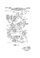
- FEGURE l is a schematic diagram of an oscillator having a remotely situated crystal according to the invention.
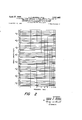
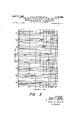
- V FIGURES 2 and 3 are charts illustrating the length of cable needed for each band to cover a specific portion of a broad range of frequencies.
- FIGURE 1 shows an oscillator unit 5 that may be utilized 'with any crystal having a frequency between 1 and megacycles.
- Each said crystal is connected to unit 5, but remotely situated with respect thereto, by means of a pair of coaxial cables substantially equal to one-half wavelength with respect to the crystal frequency.
- oscillator unit 5 consists of a very high frequency (VHF) (30-110 megacycles) section 6 and a high frequency (HF) (1-30 megacycles) section 7.
- VHF very high frequency
- HF high frequency
- the frequency of the crystal determines, of course, whether the crystal is utilized with the HF section or the V 11 section'
- the frequency range covered (here considered to be 1 rnegacycle to 110 megacycles) is divided into bands of frequencies since the associated oscillator circuitry must provide the necessary phase shift.
- eight bands are utilized, although it is to be appreciated, of course, that any number of bands might be used as are needed to conveniently break the frequency range into acceptably small portions to achieve the desired end over the entire frequency range.
- an amplifier tube 9, shown herein as a conventional triode, is provided.
- cathode of tube 9 is connected to ground through a re- 7 that is connected through parallel connected resistor 18 and inductor 20 to the grid of conventional cathode fol-' lower tubeyZZ.
- the oscillator output is taken from the cathode ofcathode follower 22, as at lead 23.
- the cathode is also connected to ground through series connected resistors 26 and 28, the junction of which resistors is connected to the control grid through resistor 30.
- the plate of cathode follower 22 is connected to a 200 volt power supply (not shown) through resistor 32 and feedthrough capacitor 34. In addition, the plate is connected with ground through capacitor as.
- the plate of amplifier tube 9 is connected with ground through a variable capacitor 3d, and to the 200 volt power supply, when the VHF section is energized, through multiposition switch 4i resistor 41, an inductor (as brought out hereinbelow), multiposition switch 42, feedthrough capacitor 43, and variable resistor 44.
- a bypass capacitor $5 is also provided between capacitor 43 and V resistor 44-.
- Inductors 46, 47, 48 and 49 are connected to pins 5 through 8, respectively, of multiposition switch 4t and the power supply must pass through one of the inductors to reach the plate of tube 9.
- the VHF section is w rotor 51.
- the feedback network from the plate to the control grid of amplifier 9 is through multiposition switches 4a and 54, each of which has an inductor connected between like pins.- Pin 5 of each is connected through inductor 56;, pin 6 of each is connected through inductor 57, pin 7 of each is connected through inductor 58, and pin 8 of each is connected through inductor .59.
- Inductors 46-49, inductors 56-59 and variable capacitor 39 form a phase shift network, only one inductor from each .through capacitor 68 to one side of resistor 69, the
- control grid also has a return to ground through resistor 7t).
- the crystal 72 to be connected from the remote location (if the crystal frequency is in the VHF range) is placed in parallel across resistor fi so that one side of the crystal is connected to the control grid and the other to the phase shifting network. As indicated in FIG- URE 1, the crystal is connected into thecircuit by a pair of coaxial cables 74 and 75', each of which has the outer conductor grounded.
- the length of coaxial cables 74 and 75 is dependent upon the frequency of the crystal selected.
- the length must be substantially one-half wavelength, of. multiples thereof, with respect to the frequency of the selected crystal.
- a high impedance is presented at each side of the crystal. This permits utilization of crystals having a resistance much larger than the characteristic impedance of the coaxial cables.
- the chart of FIGURES 2 and 3 may be referred to in ascertaining the length of cable needed for a particular frequency as Well'as the band setting of the multiposition switches. As shown in this chart, whenever a horizontal line crosses a given frequency the length of cable and the band (as shown at the left of the chart) may. properly be used for that frequency.
- HF section 7 is similar to VHF section 6, although the components are chosen, of course, to satisfy the lower frequency conditions.
- Amplifier tube 85 has a cathode that is connected to ground through parallel connected resistor 81 and capacitor 82 andan output taken from rotor of which, as brought out hereinabove, is connected to the oscillator output through cathode follower 22.
- contacts 1 and 2 of multiposition switch 16 a are connected to the control grid of amplifier through pins 3 and 4 are connected to ground through resistor 98 and capacitor 99. a a
- the plate of amplifier St) i also connected to the single contact rotor 102 of multiposition switch 193 and is con resistor 88 to the rotor of multiposition switch Eltkand 7 'through resistor 92 to contacts 3 and 4 of multiposi-' the chart of FIGURES 2 and 3.
- inductor 19? is connected to pin 1 of switch 1%
- inductor 111 is connected to pin 3
- inductor 112 is connected to pin 4.
- Inductors 109, 110 and 111 also have capacitors 114, 115 and 116 connected in parallel therewith, while bypass capacitors 113 and 119 are provided between the junction of inductors 189-112 and resistor 195.
- a phase shifting network is provided between multiposition switch 103 and multiposition switch 122.
- This phase shifting network includes the inductors and capacitors 109416, above referred to, and also includes a serially connected circuit between like pins of switches 1% and 122. As shown, pin 1 of each switch is connected to parallel connected variable inductor and resistor 126, pin 2. of each switch is connected to parallel connected variable inductor 128 and resistor 129, pin 3 of each switch is connected to parallel connected variable inductor 131 and resistor 132, and pin 4* of each switch is connected to parallel connected variable inductor 134 and resistor 135.
- Multiposition switch 163 also has a single notch rotor 137 identical to that of switches 40 and 54. Like switch 1%, switch. 122 also has a single notch rotor "138, and this rotor is directly connected by means of lead 139 to single notch rotor 137 of switch 1133. Lead 139 also has a pair of capacitors 141 and 142 to ground.
- the single contact rotor 145 of multiposition switch 122 is connected to the rotor of multiposition switch 94. However, since only pins 3 and 4 are connected to resistor 92, this resistor is in the circuit only in positions 3 and 4. 7
- the crystal When a crystal 148 in the HF frequency region is used, the crystal is connected across resistor 92 in the same manner as described hereinabove with respect to crystal '72. When resistor 92. is not in the circuit, however, then the crystal alone is connected between the phase shifting network and resistor 88 (to the control grid of amplifier 30).
- Crystal 148 is connected to HP section 7 by means of coaxial cables 15% and 151 in the same manner as crystal '72 is connected to VHF section 6, the length of the cables varying with the frequency of crystal 148,-as shown in the chart of FIGURES'Z and 3, so that the cables are maintained substantially at one-half wavelength (or multiples thereof) with respect to the crystal frequency.
- the outer conductors of coaxial cables 159 and 151 are grounded while the inner conductors connect the crystal to the unit.
- these cables may, if desired, be selected to have a length somewhat less than one-half wavelength as would be necessary to give thesdesired phase shift at a particular frequency. This however, is not desirable, at least to any great extent, at higher frequencies.
- a crystal may be chosen that is in either the high frequency or very high frequency range. If in the. VHF range, the crystal is connected to the VHF section 6 by means of a pair of equal length cable substantially one-half wavelength with respect to the crystal 7 frequency. This length may be quickly. ascertained by The multiposition includes the crystal frequency is selected, which band is also given by the chart of FIGURE 2. The proper section virtue of the length not being exactly a half wavelength or multiple thereof) and the resistance of the crystal.
- bands of frequencies have been utilized to cover a frequency range of 1 to 110 megacycles.
- the bands can be varied, as would be obvious to one skilled in the art, the bands might be selected as follows:
- novel oscillator of this invention is capable of being used with crystals that vary in frequency over a broad range of frequencies and which may be remotely situated with respect to the remainder of the oscillator circuitry, said crystals being connected thereto by means of coaxial cables of substantially onehalf wavelength.
- a crystal oscillator wherein said crystal is remotely situated with respect to the remainder of the circuitry, said oscillator comprising: an amplifier including a control electrode and an output electrode; phase shifting means connected to one of said electrodes; a crystal remotely situated with respect to said amplifier; and first and second transmission lines one of which has one end portion connected to one side of said crystal and the other end portion connected to the other of said electrodes and the other of which lines has one end portion connected to the other side of said crystal and the other end portion connected to said phase shifting means, said transmission lines being of a length so as to be substantially n/2 wavelengths with respect to the frequency of said crystal, where n is a positive integer; said phase shifting means, said transmission lines and the resistance of said crystal providing a 180 phase shift between said output electrode and said control electrode.
- a crystal oscillator wherein said crystal is remotely situated with respect to the remainder of the circuitry, said oscillator comprising: an amplifying tube having a plate, a control grid and a cathode, said cathode being connected with ground; phase shifting means connected to said plate; a crystal remotely situated with respect to said amplifying tube; a first coaxial cable the inner conductor of which is connected at one end to one side of said crystal and at the other to said phase shifting means; and a second coaxial cable the inner conductor of which is connected at one end to the other side of said crystal and at the other end to said control grid; said coaxial cables having grounded outer conductors and being substantially n/2 wavelengths with respect to the frequency of said crystal, where n is a positive integer; said phase shifting means, said coaxial cables and the resistance of said crystal providing a phase shift between said plate and said grid.
- a crystal oscillator capable of being utilized with any crystal Within a broad range of frequencies and wherein said crystal is remotely situated with respect to the remainder of the circuitry, said oscillator comprising: a crystal; an amplifier including a control electrode and an output electrode; a plurality of phase shifting means;
- first and second transmission lines one of which has one end portion connected to one side of said crystal and the other end connected to said phase shifting means selected, and the other of which lines has one end portion connected to the other side of said crystal and the other end portion connected to the other said electrode, the length of said transmission lines being chosen so as to be substantially n/ 2 wavelengths with respect to frequency of said crystal, when n is a positive integer; said phase shifting means selected being dependent upon the frequency of said crystal so that phase shifting means selected, said transmission lines and the resistance of said crystal provide a 180 phase shift between said output electrode and said control electrode.
- a crystal oscillator capable of being utilized with any crystal within a broad range of frequencies and wherein said crystal is remotely situated with respect to the remainder of the circuitry, said oscillator comprising: a crystal; a high frequency amplifier and a very high frequency amplifier each of which includes a control electrode and an output electrode; a plurality of phase shifting networks; means for connecting one of said phase shifting networks to one said electrode of one said amplifier, said amplifier selected being dependent upon the frequency of said crystal; a first coaxial cable the inner conductor of which has one end portion connected to one side of said crystal and the other end portion connected to said phase shifting network selected; and a second coaxial cable the inner conductor of which has one end portion connected to the other side of said crystal and the other end portion connected to the other said electrode of said amplifier selected; the outer condoctors of said coaxial cables being connected to ground; the length of said coaxial cables being varied so as to always have a length substantially equal to n/2 wavelengths with respect to the frequency of said crystal, where n is a positive integer; said phase shifting network selected being dependent
Landscapes
- Oscillators With Electromechanical Resonators (AREA)
Description
D TO
A ril 27, 1965 H. P. BROWER ETAL OSCILLATOR HAVING REMOTELY SITUATED CRYSTAL CONNECTE REMAINING CIRQUITRY BY TRANSMISSION LINES SUBSTANTIALLY'M; WAVELENGTHS WITH RESPECT TO SAID CRYSTAL FREQUENCY 3 Sheets-Sheet 1 Filed Oct. 8, 1962 INVENTORS HARLEY R BROWER BY MARVIN E. FRERKING ATTORNEYS April 27, 1965 7 Filed Oct. 8, 1962 CABLEv LENGTH (FEET) H P. BROWER . ETAL 3, 81, 82
OSCILLATOR HAVING REMOTELY SITUATED CRYSTAL CONNECTED TO REMAINING CIRCUITRY BY TRANSMISSION LINES SUBSTANTIALLY'V;WAVELENGTHS WITH RESPECT TO SAID CRYSTAL FREQUENCY 3 Sheets-Sheet 2 A m m a m an a on NI- ml- L A a m mamm a m mam on NI- 1 mlm a as m a m m a a 4 5 s 1 910 FREQUENCY (MC) INVENTORS HARLEY P. BROWER BY MARVIN E. FRERKING ATTORNEYS P" 1965 H. P. BROWER ETAL 3,131,082
OSCILLATOR HAVING REMOTELY SITUATED CRYSTAL CONNECTED TO REMAINING CIRCUITRY BY TRANSMISSION LINES SUBSTANTIALLY.T ZZWAVELENGTHS WITH RESPECT TO SAID CRYSTAL FREQUENCY v Filed Oct. 8, 1962 s Sheets-Sheet s CABLE LENGTH (FEET) 3O 4O 5O 6O 7O 90 HO FREQUENCY (MC) INVENTORS HARLEY P BROWER BY MARVIN E. FRERKING ATTORNEYS United States Patent GSCILLATGP. HAVHQG REMUEELY SITUATED CRYSTAL QONNEQTEB) T0 REMAlNH lG CIR- CUITRY BY TRANSMESQUN LINES SUBSTAN- TEALLY n/Z WA nLENGTHS WETH REPET T0 SAED KIRYSTAL FREQUENtIY Harley P. Brewer and l /iarvin E. Frerking, Qedar Rapids, Iowa, assignors to tlollins Radio Company, Cedar Rapids, Iowa, a corporation of Iowa Filed Oct. 8, 1962, Ser. No. 229,073 4 Claims. (ill. 33i-49) This invention relates to a crystal oscillator and more particularly to an oscillator having a remotely situated cr' st'al that is connected to the remainder of the circuitry by means of a pair of one-half wavelength coaxial cables.
It sometimes becomes necessary to locate the crystal of a crystal oscillator at a distance from the remainder of the oscillator circuitry. Such might be the case, for example, where the crystal is to be tested for frequency deviation under vibration conditions or where the crystal is to be maintained at constant tern erature in an oven or the like.
in addition, it is also frequently desirable to have a single oscillator unit that can produce an output signal of any requency (as determined by the crystal connected to the unit) over a broad range of frequencies.
While crystal oscillators are known that include transmission lines to connect a crystal to the remainder of the oscillator circuitry, these known oscillators have not fully solved the problem or" providing an oscillator unit that can be used with any one of a plurality of crystals over a broad range of frequencies. In addition, no known oscillator circuit is capable of operation with a crystal having a resistance much larger than the characteristic impedance of the transmission line connecting the crystal to the remainder of the oscillator circuitry.
it is a feature of this invention that an oscillator unit is provided that is capable of use with crystals over a broad range of frequencies. It is another feature of this invention that each crystal is remotely situated with respect to the remainder of the oscillator circuitry and is connected thereto by means of a pair or" substantially one-half wavelength (or multiples thereof) coaxial cables.
It is therefore an object of this invention to provide a crystal oscillator capable of utilization over a broad range of freq iencies.
it is another object of this invention to provide an oscillator having a remotely situated crystal connected to the remainder of the oscillator circuitry by means of coaxial cables that have a length substantially equal to 22/2 wavelengths with respect to the frequency of said crystal, where n is a positive integer.
More particularly, it is an object of this invention to provide a crystal oscillator having a remotely situated crystal connected by means of substantially one-half wavelength (or multiples thereof) coaxial cables to the remainder of the oscillator circuitry whereby said oscillator may be utilized with crystals having much greater resistance than the characteristic impedance of said cables.
With these and other objects in view which will become apparent to one skilled inthe art as the description procoeds, this invention resides in the novel construction, combination and arrangement of parts substantially as hereinafter described and more particularly defined by the appended clai1ns,it being understood that such changes fiddlfidZ Patented Apr. '27, T1955 ice in the precise embodiment of theherein disclosed inven-" tion may be included as come within the scope of the claims.
The accompanying drawings illustrate one complete example of the embodiment of the invention constructed according to the best mode so far devised for the practical application of the principles thereof, and in which:
FEGURE l is a schematic diagram of an oscillator having a remotely situated crystal according to the invention; and V FIGURES 2 and 3 are charts illustrating the length of cable needed for each band to cover a specific portion of a broad range of frequencies.
Referring now to the drawings, FIGURE 1 shows an oscillator unit 5 that may be utilized 'with any crystal having a frequency between 1 and megacycles. Each said crystal is connected to unit 5, but remotely situated with respect thereto, by means of a pair of coaxial cables substantially equal to one-half wavelength with respect to the crystal frequency.
As shown in the drawing, oscillator unit 5 consists of a very high frequency (VHF) (30-110 megacycles) section 6 and a high frequency (HF) (1-30 megacycles) section 7. The frequency of the crystal determines, of course, whether the crystal is utilized with the HF section or the V 11 section' The frequency range covered (here considered to be 1 rnegacycle to 110 megacycles) is divided into bands of frequencies since the associated oscillator circuitry must provide the necessary phase shift. As shown in the drawing, eight bands are utilized, although it is to be appreciated, of course, that any number of bands might be used as are needed to conveniently break the frequency range into acceptably small portions to achieve the desired end over the entire frequency range.
Referring to the VHF section 6, an amplifier tube 9, shown herein as a conventional triode, is provided. The
cathode of tube 9 is connected to ground through a re- 7 that is connected through parallel connected resistor 18 and inductor 20 to the grid of conventional cathode fol-' lower tubeyZZ.
As is conventional, the oscillator output is taken from the cathode ofcathode follower 22, as at lead 23. The cathode is also connected to ground through series connected resistors 26 and 28, the junction of which resistors is connected to the control grid through resistor 30. The plate of cathode follower 22 is connected to a 200 volt power supply (not shown) through resistor 32 and feedthrough capacitor 34. In addition, the plate is connected with ground through capacitor as.
The plate of amplifier tube 9 is connected with ground through a variable capacitor 3d, and to the 200 volt power supply, when the VHF section is energized, through multiposition switch 4i resistor 41, an inductor (as brought out hereinbelow), multiposition switch 42, feedthrough capacitor 43, and variable resistor 44. A bypass capacitor $5 is also provided between capacitor 43 and V resistor 44-.
The feedback network from the plate to the control grid of amplifier 9 is through multiposition switches 4a and 54, each of which has an inductor connected between like pins.- Pin 5 of each is connected through inductor 56;, pin 6 of each is connected through inductor 57, pin 7 of each is connected through inductor 58, and pin 8 of each is connected through inductor .59. Inductors 46-49, inductors 56-59 and variable capacitor 39 form a phase shift network, only one inductor from each .through capacitor 68 to one side of resistor 69, the
other side of which is connected to the control grid of amplifier 9. The control grid also has a return to ground through resistor 7t). V
The crystal 72 to be connected from the remote location (if the crystal frequency is in the VHF range) is placed in parallel across resistor fi so that one side of the crystal is connected to the control grid and the other to the phase shifting network. As indicated in FIG- URE 1, the crystal is connected into thecircuit by a pair of coaxial cables 74 and 75', each of which has the outer conductor grounded.
The length of coaxial cables 74 and 75 is dependent upon the frequency of the crystal selected. The length, however, must be substantially one-half wavelength, of. multiples thereof, with respect to the frequency of the selected crystal. By utilizing this length of cable, a high impedance is presented at each side of the crystal. This permits utilization of crystals having a resistance much larger than the characteristic impedance of the coaxial cables.
The chart of FIGURES 2 and 3 may be referred to in ascertaining the length of cable needed for a particular frequency as Well'as the band setting of the multiposition switches. As shown in this chart, whenever a horizontal line crosses a given frequency the length of cable and the band (as shown at the left of the chart) may. properly be used for that frequency.
As shown, contacts 1 and 2 of multiposition switch 16 a are connected to the control grid of amplifier through pins 3 and 4 are connected to ground through resistor 98 and capacitor 99. a a
The plate of amplifier St) i also connected to the single contact rotor 102 of multiposition switch 193 and is con resistor 88 to the rotor of multiposition switch Eltkand 7 'through resistor 92 to contacts 3 and 4 of multiposi-' the chart of FIGURES 2 and 3.
switches are then rotated and the band of frequencies that.
nected to the 200'volt power supply through switch 103, resistor 195, multiposition switch 1%, feedthrough capacitor 43 and variable resistor 44. In addition, the power also passes through the inductor connected to each of the first four pins of switch 1533. As shown, inductor 19? is connected to pin 1 of switch 1%, inductor is connected to pin 2, inductor 111 is connected to pin 3, and inductor 112 is connected to pin 4. Inductors 109, 110 and 111 also have capacitors 114, 115 and 116 connected in parallel therewith, while bypass capacitors 113 and 119 are provided between the junction of inductors 189-112 and resistor 195. I
A phase shifting network is provided between multiposition switch 103 and multiposition switch 122. This phase shifting network includes the inductors and capacitors 109416, above referred to, and also includes a serially connected circuit between like pins of switches 1% and 122. As shown, pin 1 of each switch is connected to parallel connected variable inductor and resistor 126, pin 2. of each switch is connected to parallel connected variable inductor 128 and resistor 129, pin 3 of each switch is connected to parallel connected variable inductor 131 and resistor 132, and pin 4* of each switch is connected to parallel connected variable inductor 134 and resistor 135.
Multiposition switch 163 also has a single notch rotor 137 identical to that of switches 40 and 54. Like switch 1%, switch. 122 also has a single notch rotor "138, and this rotor is directly connected by means of lead 139 to single notch rotor 137 of switch 1133. Lead 139 also has a pair of capacitors 141 and 142 to ground.
The single contact rotor 145 of multiposition switch 122 is connected to the rotor of multiposition switch 94. However, since only pins 3 and 4 are connected to resistor 92, this resistor is in the circuit only in positions 3 and 4. 7
When a crystal 148 in the HF frequency region is used, the crystal is connected across resistor 92 in the same manner as described hereinabove with respect to crystal '72. When resistor 92. is not in the circuit, however, then the crystal alone is connected between the phase shifting network and resistor 88 (to the control grid of amplifier 30).
In operation, a crystal may be chosen that is in either the high frequency or very high frequency range. If in the. VHF range, the crystal is connected to the VHF section 6 by means of a pair of equal length cable substantially one-half wavelength with respect to the crystal 7 frequency. This length may be quickly. ascertained by The multiposition includes the crystal frequency is selected, which band is also given by the chart of FIGURE 2. The proper section virtue of the length not being exactly a half wavelength or multiple thereof) and the resistance of the crystal.
As shown in the drawing, eight bands of frequencies have been utilized to cover a frequency range of 1 to 110 megacycles. Although the bands can be varied, as would be obvious to one skilled in the art, the bands might be selected as follows:
In view of the foregoing, it should be evident to those skilled in the art that the novel oscillator of this invention is capable of being used with crystals that vary in frequency over a broad range of frequencies and which may be remotely situated with respect to the remainder of the oscillator circuitry, said crystals being connected thereto by means of coaxial cables of substantially onehalf wavelength.
What is claimed as our invention is:
l. A crystal oscillator wherein said crystal is remotely situated with respect to the remainder of the circuitry, said oscillator comprising: an amplifier including a control electrode and an output electrode; phase shifting means connected to one of said electrodes; a crystal remotely situated with respect to said amplifier; and first and second transmission lines one of which has one end portion connected to one side of said crystal and the other end portion connected to the other of said electrodes and the other of which lines has one end portion connected to the other side of said crystal and the other end portion connected to said phase shifting means, said transmission lines being of a length so as to be substantially n/2 wavelengths with respect to the frequency of said crystal, where n is a positive integer; said phase shifting means, said transmission lines and the resistance of said crystal providing a 180 phase shift between said output electrode and said control electrode.
2. A crystal oscillator wherein said crystal is remotely situated with respect to the remainder of the circuitry, said oscillator comprising: an amplifying tube having a plate, a control grid and a cathode, said cathode being connected with ground; phase shifting means connected to said plate; a crystal remotely situated with respect to said amplifying tube; a first coaxial cable the inner conductor of which is connected at one end to one side of said crystal and at the other to said phase shifting means; and a second coaxial cable the inner conductor of which is connected at one end to the other side of said crystal and at the other end to said control grid; said coaxial cables having grounded outer conductors and being substantially n/2 wavelengths with respect to the frequency of said crystal, where n is a positive integer; said phase shifting means, said coaxial cables and the resistance of said crystal providing a phase shift between said plate and said grid.
3. A crystal oscillator capable of being utilized with any crystal Within a broad range of frequencies and wherein said crystal is remotely situated with respect to the remainder of the circuitry, said oscillator comprising: a crystal; an amplifier including a control electrode and an output electrode; a plurality of phase shifting means;
means for selectively connecting one of said phase shifting means to one of said electrodes; and first and second transmission lines one of which has one end portion connected to one side of said crystal and the other end connected to said phase shifting means selected, and the other of which lines has one end portion connected to the other side of said crystal and the other end portion connected to the other said electrode, the length of said transmission lines being chosen so as to be substantially n/ 2 wavelengths with respect to frequency of said crystal, when n is a positive integer; said phase shifting means selected being dependent upon the frequency of said crystal so that phase shifting means selected, said transmission lines and the resistance of said crystal provide a 180 phase shift between said output electrode and said control electrode.
4. A crystal oscillator capable of being utilized with any crystal within a broad range of frequencies and wherein said crystal is remotely situated with respect to the remainder of the circuitry, said oscillator comprising: a crystal; a high frequency amplifier and a very high frequency amplifier each of which includes a control electrode and an output electrode; a plurality of phase shifting networks; means for connecting one of said phase shifting networks to one said electrode of one said amplifier, said amplifier selected being dependent upon the frequency of said crystal; a first coaxial cable the inner conductor of which has one end portion connected to one side of said crystal and the other end portion connected to said phase shifting network selected; and a second coaxial cable the inner conductor of which has one end portion connected to the other side of said crystal and the other end portion connected to the other said electrode of said amplifier selected; the outer condoctors of said coaxial cables being connected to ground; the length of said coaxial cables being varied so as to always have a length substantially equal to n/2 wavelengths with respect to the frequency of said crystal, where n is a positive integer; said phase shifting network selected being dependent upon the frequency of said crystal so that said phase shifting network selected, said coaxial cables and the resistance of said crystal provide a 180 phase shift between said output electrode and said control electrode.
References Cited by the Examiner UNITED STATES PATENTS 2,272,851 2/42 Ramsay 33ll01 2,683,810 7/54 Mortley 331-458 ROY LAKE, Primary Examiner.
JOHN KOMINSKI, Examiner.
Claims (1)
1. A CRYSTAL OSCILLATOR WHEREIN SAID CRYSTAL IS REMOTELY SITUATED WITH RESPECT TO THE REMAINDER OF THE CIRCUITRY, SAID OSCILLATOR COMPRISING: AN AMPLIFIER INCLUDING A CONTROL ELECTRODE AN AN OUTPUT ELECTRODE; PHASE SHIFTING MEANS CONNECTED TO ONE OF SAID ELECTRODES; A CRYSTAL REMOTELY SITUATED WITH RESPECT TO SAID AMPLIFIER; AND FIRST AND SECOND TRANSMISSION LINES ONE OF WHICH HAS ONE END PORTION CONNECTED TO ONE SIDE OF SAID CRYSTAL AND THE OTHER END PORTION CONNECTED TO THE OTHER OF SAID ELECTRODES AND THE OTHER OF WHICH LINES HAS ONE END PORTION CONNECTED TO THE OTHER SIDE OF SAID CRYSTAL AND THE OTHER END PORTION CONNECTED TO SAID PHASE SHIFTING MEANS, SAID TRANSMISSION LINES BEING OF A LENGTH SO AS TO BE SUBSTANTIALLY N/2 WAVELENGTHS WITH RESPECT TO THE FREQUENCY OF SAID CRYSTAL, WHERE N IS A POSITIVE INTEGER; SAID PHASE SHIFTING MEANS, SAID TRANSMISSION LINES AND THE RESISTANCE OF SAID
Priority Applications (1)
| Application Number | Priority Date | Filing Date | Title |
|---|---|---|---|
| US229078A US3181082A (en) | 1962-10-08 | 1962-10-08 | Oscillator having remotely situated crystal connected to remaining circuitry by transmission lines substantally n/2 wavelengths with respect to said crystal frequency |
Applications Claiming Priority (1)
| Application Number | Priority Date | Filing Date | Title |
|---|---|---|---|
| US229078A US3181082A (en) | 1962-10-08 | 1962-10-08 | Oscillator having remotely situated crystal connected to remaining circuitry by transmission lines substantally n/2 wavelengths with respect to said crystal frequency |
Publications (1)
| Publication Number | Publication Date |
|---|---|
| US3181082A true US3181082A (en) | 1965-04-27 |
Family
ID=22859768
Family Applications (1)
| Application Number | Title | Priority Date | Filing Date |
|---|---|---|---|
| US229078A Expired - Lifetime US3181082A (en) | 1962-10-08 | 1962-10-08 | Oscillator having remotely situated crystal connected to remaining circuitry by transmission lines substantally n/2 wavelengths with respect to said crystal frequency |
Country Status (1)
| Country | Link |
|---|---|
| US (1) | US3181082A (en) |
Citations (2)
| Publication number | Priority date | Publication date | Assignee | Title |
|---|---|---|---|---|
| US2272851A (en) * | 1938-02-17 | 1942-02-10 | Rca Corp | Electrical oscillation generator |
| US2683810A (en) * | 1949-03-30 | 1954-07-13 | Marconi Wireless Telegraph Co | Piezoelectric crystal oscillator |
-
1962
- 1962-10-08 US US229078A patent/US3181082A/en not_active Expired - Lifetime
Patent Citations (2)
| Publication number | Priority date | Publication date | Assignee | Title |
|---|---|---|---|---|
| US2272851A (en) * | 1938-02-17 | 1942-02-10 | Rca Corp | Electrical oscillation generator |
| US2683810A (en) * | 1949-03-30 | 1954-07-13 | Marconi Wireless Telegraph Co | Piezoelectric crystal oscillator |
Similar Documents
| Publication | Publication Date | Title |
|---|---|---|
| US2860308A (en) | High frequency transmission line coupling device | |
| US3546636A (en) | Microwave phase shifter | |
| US2757344A (en) | Tuner | |
| US2427107A (en) | Centimeter wave apparatus | |
| US2440269A (en) | Tunable oscillator | |
| US2550524A (en) | Balanced microwave detector | |
| JPS6343002B2 (en) | ||
| US2637813A (en) | Balanced microwave detector | |
| US3512105A (en) | Linear voltage tuned microwave resonant circuits and oscillators | |
| US2519524A (en) | Multiple-tuned wave-selector system | |
| US2494345A (en) | Multifrequency oscillation | |
| US2978579A (en) | Signal mixers | |
| US3369189A (en) | Variable feedback notch filter | |
| US2852671A (en) | Method and apparatus for frequency division | |
| US3443199A (en) | Wave frequency multiplier employing a nonlinear device in a band-pass filter | |
| US2666183A (en) | Variable attenuator | |
| US2453453A (en) | Frequency modulation system | |
| US2476885A (en) | Mixer for microwave receivers | |
| US3197720A (en) | Transmission line having frequency reject band | |
| US2863042A (en) | Echo transmitter and receiver having means to produce stable intermediate frequency despite transmitter frequency drift | |
| US2505572A (en) | Tuning unit | |
| US2363641A (en) | Low loss tuning apparatus | |
| US2633534A (en) | Variable frequency oscillator | |
| US2275587A (en) | Signal combining network | |
| US2693582A (en) | Variable coupling device |