US3180408A - Heat exchanger apparatus - Google Patents
Heat exchanger apparatus Download PDFInfo
- Publication number
- US3180408A US3180408A US119110A US11911061A US3180408A US 3180408 A US3180408 A US 3180408A US 119110 A US119110 A US 119110A US 11911061 A US11911061 A US 11911061A US 3180408 A US3180408 A US 3180408A
- Authority
- US
- United States
- Prior art keywords
- tubesheet
- tubes
- shell
- hollow member
- bundle
- Prior art date
- Legal status (The legal status is an assumption and is not a legal conclusion. Google has not performed a legal analysis and makes no representation as to the accuracy of the status listed.)
- Expired - Lifetime
Links
- 239000012530 fluid Substances 0.000 claims description 12
- 239000007789 gas Substances 0.000 description 18
- XLYOFNOQVPJJNP-UHFFFAOYSA-N water Substances O XLYOFNOQVPJJNP-UHFFFAOYSA-N 0.000 description 10
- 239000001307 helium Substances 0.000 description 5
- 229910052734 helium Inorganic materials 0.000 description 5
- SWQJXJOGLNCZEY-UHFFFAOYSA-N helium atom Chemical compound [He] SWQJXJOGLNCZEY-UHFFFAOYSA-N 0.000 description 5
- 239000002184 metal Substances 0.000 description 5
- 230000002093 peripheral effect Effects 0.000 description 5
- 238000010276 construction Methods 0.000 description 1
- 230000009977 dual effect Effects 0.000 description 1
- 238000010438 heat treatment Methods 0.000 description 1
- 239000003779 heat-resistant material Substances 0.000 description 1
- 238000009413 insulation Methods 0.000 description 1
- 229920006395 saturated elastomer Polymers 0.000 description 1
Images


Classifications
-
- F—MECHANICAL ENGINEERING; LIGHTING; HEATING; WEAPONS; BLASTING
- F22—STEAM GENERATION
- F22B—METHODS OF STEAM GENERATION; STEAM BOILERS
- F22B1/00—Methods of steam generation characterised by form of heating method
- F22B1/02—Methods of steam generation characterised by form of heating method by exploitation of the heat content of hot heat carriers
- F22B1/18—Methods of steam generation characterised by form of heating method by exploitation of the heat content of hot heat carriers the heat carrier being a hot gas, e.g. waste gas such as exhaust gas of internal-combustion engines
- F22B1/1823—Methods of steam generation characterised by form of heating method by exploitation of the heat content of hot heat carriers the heat carrier being a hot gas, e.g. waste gas such as exhaust gas of internal-combustion engines for gas-cooled nuclear reactors
-
- F—MECHANICAL ENGINEERING; LIGHTING; HEATING; WEAPONS; BLASTING
- F22—STEAM GENERATION
- F22B—METHODS OF STEAM GENERATION; STEAM BOILERS
- F22B21/00—Water-tube boilers of vertical or steeply-inclined type, i.e. the water-tube sets being arranged vertically or substantially vertically
- F22B21/22—Water-tube boilers of vertical or steeply-inclined type, i.e. the water-tube sets being arranged vertically or substantially vertically built-up from water tubes of form other than straight or substantially straight
- F22B21/30—Water-tube boilers of vertical or steeply-inclined type, i.e. the water-tube sets being arranged vertically or substantially vertically built-up from water tubes of form other than straight or substantially straight bent in U-loop form
-
- F—MECHANICAL ENGINEERING; LIGHTING; HEATING; WEAPONS; BLASTING
- F22—STEAM GENERATION
- F22G—SUPERHEATING OF STEAM
- F22G3/00—Steam superheaters characterised by constructional features; Details or component parts thereof
- F22G3/009—Connecting or sealing of superheater or reheater tubes with collectors or distributors
-
- F—MECHANICAL ENGINEERING; LIGHTING; HEATING; WEAPONS; BLASTING
- F28—HEAT EXCHANGE IN GENERAL
- F28D—HEAT-EXCHANGE APPARATUS, NOT PROVIDED FOR IN ANOTHER SUBCLASS, IN WHICH THE HEAT-EXCHANGE MEDIA DO NOT COME INTO DIRECT CONTACT
- F28D7/00—Heat-exchange apparatus having stationary tubular conduit assemblies for both heat-exchange media, the media being in contact with different sides of a conduit wall
- F28D7/06—Heat-exchange apparatus having stationary tubular conduit assemblies for both heat-exchange media, the media being in contact with different sides of a conduit wall the conduits having a single U-bend
-
- Y—GENERAL TAGGING OF NEW TECHNOLOGICAL DEVELOPMENTS; GENERAL TAGGING OF CROSS-SECTIONAL TECHNOLOGIES SPANNING OVER SEVERAL SECTIONS OF THE IPC; TECHNICAL SUBJECTS COVERED BY FORMER USPC CROSS-REFERENCE ART COLLECTIONS [XRACs] AND DIGESTS
- Y10—TECHNICAL SUBJECTS COVERED BY FORMER USPC
- Y10S—TECHNICAL SUBJECTS COVERED BY FORMER USPC CROSS-REFERENCE ART COLLECTIONS [XRACs] AND DIGESTS
- Y10S165/00—Heat exchange
- Y10S165/355—Heat exchange having separate flow passage for two distinct fluids
- Y10S165/40—Shell enclosed conduit assembly
- Y10S165/401—Shell enclosed conduit assembly including tube support or shell-side flow director
- Y10S165/405—Extending in a longitudinal direction
- Y10S165/407—Extending in a longitudinal direction internal casing or tube sleeve
- Y10S165/409—Extending in a longitudinal direction internal casing or tube sleeve including transverse element, e.g. fin, baffle
Definitions
- This invention relates to heat exchange apparatus and is particularly directed to improvements in a steam generator which uses high temperature gas at high flow rates as a source of heat.
- One of the difficulties encountered in providing a steam generator of this type is that the temperature of the superheated steam tubes is so much higher than that of certain other tubes in the tube bundle as to cause difficulty because of differences in thermal expansion.
- An important object of this invention is to provide a novel form of heat exchanger employing a'first tubesheet for connection with a major portion of the tubes in the tube bundle and a second tubesheet fixedin a novel manner to the first tubesheet and being connected to the hot pass portion of the superheater tubes.
- Another object is to provide a novel form of tube field pattern for use with said dual tubesheets.
- Another object is to provide a means for trapping any leakage of fluids which escape from the tube joints that connect the tubes to the tubesheet and which would otherwise be exposed to the stream of hot gases passing through the shell of the heat exchanger device.
- Another object is to provide a novel form of concentric inlet and outlet terminal device for introducing steam into the heat exchanger and for withdrawing superheated steam therefrom.
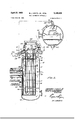
- FIGURE 1 is a top plan view in diagrammatic form .showing a preferred embodiment-of our invention.
- FIGURE 6 is a sectional plan view taken substantially on the lines 6-5 as shown in FIGURE 2.
- FIGURE 7 is a sectional plan view taken substantially on the lines 7 7 as shown in FIGURE 2.
- the heat exchanger or steam generator generally designated ltlincludes a shell 11, a tubesheet 12 and a hollow member 13.
- the tubesheet 12 integrally joins the hollow 'ice U-bend tubes, including the economizer tubes 17, the evaporator tubes 18 and the superheater tubes 19. Both ends of each of the economizer tubes 17 and the evaporator tubes 18 are fixed in a conventional manner within the tubesheet 12 and communicate with the space within the interior of the hollow member 13. Only one end of each of the superheater tubes 19 is fixed within the tubesheet 12, however, and the other end of each superheater tube 19 is fixed as described below.
- Hot gas such as helium enters the shell 11 through the inlet'pipe 21 and after passing across the tube bundle 16 the cooled helium gas emerges through the outlet pipe 22. After passing through a compressor (not shown) and after being heated, the helium is recirculated and again passes inward through the pipe 21 into the shell 11.
- the hollow member 13 may be provided with a flanged opening 25 and this opening may be sealed by means of the closure plate 26 whichis normally bolted and then welded in closed position.
- Flow directing means generally designated 27 are provided within the hollow member 13 and, as shown in the drawings, includes plates 28 forming passages 29, 30, and 31 each communicating with a plurality of tube openings in the tubesheet 12.
- An inlet fitting 32 on the hollow member 13 allows feed Water to enter the passage 29 and to enter the cold pass side of each of the economizer tubes 17.
- the water emerging from the upper ends of the hot pass sides of the U-bend economizer tubes 17 enters the passage and emerges from pumped to the inlet nozzle 34 on the hollow member 13.
- This hot water enters the passage 31 which communicates with the inlet pass side of each of the evaporator tubes 18.
- Wet steam from the outlet pass ends of the evaporator tubes enters the passage 35 and emerges through outlet nozzle 36.
- the wet steam from nozzle 36 enters the separate steam drum 4th through inlet nozzle 41.
- Mechanical apparatus within the steam drum 40 is of conventional type and serves to separate the steam and water and to discharge water through the outlet 42 and saturated steam through the outlet 43.
- the water from the outlet 42 includes the feed Water stream.
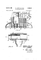
- the steam from the outlet 43 enters the concentric inlet and outlet fitting 44 through lateral terminal 45.
- the steam enters the interior of hollow member 13 through the passage 46 formed between the outer pipe member 4-7 and the inner pipe member 48. This steam within the hollow member 13 enters the cold pass side of the superheater tubes 19.
- the shell 11 is generally cylindrical in form and is preferably placed in upright vertical position.
- the shell 11 includes a bottom wall 14 and a tapered portion 15 connectedto the tubesheet 12.
- a tube bundle 16 is mounted in upright position within the shell 11 and this bundle includes a large number of upstanding integral rim 51.
- the tubesheet 12 isprovided with an axially extending offset opening 52 and is also provided with a'concentric groove 53 defining a depending skirt 54.
- the upstanding rim 51 of the second tubesheet 56 is welded at 55 to the depending skirt 54 of the first tubesheet 12.
- the duct 56 formed of heat resistant metal, is fixed to the second tubesheet 50 at its lower end 57.
- a lateral port 58 in the metal duct 56 connects with the inner pipe 43, so that superheated steam emerging from the tubes 19 passes through'the duct 56, lateral port 58 and outward through the inner pipe 48 and through the discharge nozzle 59.
- the high temperature superheated steam does not con tact the walls of the shell 11 nor the hollow member 13, and does not contact the main tubesheet 12. Moreover, the hot inner pipe 48 does not heat the hollow member 13 to an excessive degree because of the construction of the combined inlet and outlet fitting 44.
- the inner pipe 48 is preferably enclosed within a tubular sleeve or shield 60 which extends from a location adjacent the discharge nozzle 59 to a position within the interior of the hollow member 13.
- a continuous wire 61 is wrapped helically on the outer surface of the inner pipe 48 and the shield 60, which is formed of heat resistant metal, is mounted on the wire 61. Thermal insulation is enhanced by the presence of the annular space provided by the wire 61 between the inner pipe 48 and the shield 65).
- FIGURE 3 A novel form of tube field. is employed and is best shown in FIGURE 3.
- the cold pass ends of the superheater tubes 19 are arranged in a half circle or crescent shape field 62 adjacent the perforated impingement baffle 63.
- the hot pass ends of the superheater tubes i9 terminate in the second or lowered tubesheet 59. These are arranged in a field pattern 64 which is roughly circular.
- Metal shrouds 65 are provided with portions in; which project into the circular pattern 64 in a radial direction.
- the positions of the holes in the lowered tubesheet are such that the pattern 64 allows for substantially uniform heating of the hot pass portions of the superheater tubes 19 as the hot gases within the shell 11 pass from the left side of the bafile portions 66 to the right side thereof, as viewed in FIGURE 3. It will be observed that only one end of each of the superheater tubes 19 is received by the second or lowered tubesheet Both ends of all of the other tubes are fixed to the tubesheet 12. As shown in FIGURE 3, the field pattern 67 relates to the cold pass of the economizertubes l7 and the field pattern 68 relates to the hot pass of the same tubes.
- the field pattern 69 relates to the inlet pass of the evaporator tubes 18 and the field pattern 7% relates to the outlet pass of the same tubes. It will be further noted that, while the fluid in the economizer tubes 17 and the evaporator tubes 18 flows in countercurrent relationship with respect to the hot gas in the shell 11, the fluid in the superheater tubes 19 flows in concurrent relationship with such hot gas. In this way, the temperature of the metal of the superheater tubes may be maintained within acceptable limits.
- Gas flow through the shell 11 is best shown in FIG- URE 7.
- the gas inlet pipe 21 enters the curved shroud 71 and the gas impinges upon the apertured plate 63, and portions of the gas stream are deflected above and below the plate 63.
- Gas passes through the semi-circular or crescent shaped tube field 62, and then tube field 64 and between the shroud portions 6 6.
- the hot gas then passes through the tube fields 70, 69, 68 and 67, in that order, emerging into the interior of the shell 11 through the gap 72 between the shroud ends 73. It will be observed that the gas does not contact the shell until after passing all of the heat exchange tubes, and hence the shell remains relatively cool.
- the cooled gas then passes out of the shell 11 through the outlet pipe. 22.
- Means are provided for preventing any leakage of water or other fluid from the tube joints and passing into the stream of hot gas within the shell 11.
- a baffle member75 having side walls 76 and a bottom wall 77. (See FEGURE 4.)
- This baffle 75 cooperates with the lower side of the tubesheet 12 to form a leakage chamber 73. All of the tubes 17, 18 and 19 pass through openings in the bottom wall 77. Any leakage of water or steam from the openings in the tubesheet 12 or tubesheet 5%? is collected within the baflie 75 and is drawn oflf through a discharge line 79. This line 79 emerges through the wall of the shell 11, at a location not shown.
- a heat exchanger the combination of: a shell, a hollow member located at one end of the sheil, a first tubesheet integrally connecting the shell and the hollow member, a bundle of U-bend tubes positioned within said shell, certain of said tubes each having both ends fixed to said tubesheet, said tubesheet having an axial opening extending therethrough, a second tubesheet positioned within the shell adjacent the first tubesheet, means including weld means fixing the second tubesheet to the first tubesheet in alignment with said opening, certain other of said tubes each having one end fixed to the first said tubesheet and the other end fixed to said second tubesheet, a duct fixed to the second tubesheet and communicating with said other end of the latter said tubes,.
- conduit means communicating with said duct and extending exteriorly of said hollow member. and means including an inlet and an outlet on said shell for causing a flow of hot fluid across said bundle of tubes.
- a shell in a heat exchanger, the combination of: a shell, a hollow member located at one end of the shell, a first circular tubesheet integrally connecting the shell and the hollow member, a bundle of U-bend tubes positioned within said shell, certain of said tubes each having both ends fixed to said tubesheet, said tubesheet having an axial opening extending therethrough and offset from.
- a heat exchanger the combination of: a shell, a hollow member located at one end of the shell, a first circular tubesheet integrally connecting the shell and the hollow member, a bundle of U-bend tubes positioned within said shell, certain of said tubes each having both ends fixed to said tubesheet, said tubesheet having an axial opening extending therethrough, a second tubesheet having a peripheral rim and positioned within the shell adjacent the first tubesheet, means including weld means fixing said peripheral rim to the first said tubesheet, certain other of said tubes each having one end fixed to the first said tubesheet and the other end fixed to said second tubesheet, said other end of the latter said tubes terminating short of said first tubesheet and not extending through said axial opening, and means including an inlet and an outlet on said shell for causing a flow of hot fluid across said bundle of tubes.
- a shell located at one end of the shell, a first circular tubesheet integrally connecting the shell and the hollow member, a bundle of U-bend tubes positioned within said shell, certain of said tubes each having both ends fixed to said tubesheet, said tubesheet having an axial opening extending therethrough, a groove in the tubesheet adjacent said bundle and encircling said opening to define a skirt, a second tubesheet having a peripheral rim, weld means joining said skirt to said rim, certain other of said tubes each having one end fixed to the first tubesheet and the other end fixed to said second tubesheet, a duct fixed to the second tubesheet and communicating with said other end of the latter said tubes, said duct extending through said axial opening but spaced from the first tubesheet and projecting into said hollow member, conduit means communicating with said duct and extending exteriorly of said hollow member, and means including an inlet and an outlet on said shell for causing a flow of hot fiuid across said bundle of tubes.
- a heat exchanger the combination of: an upright generally cylindrical shell, a hollow member supported at the upper end of the shell, a first circular tubesheet integrally connecting the shell and the hollow member, and upright bundle of tubes positioned within said shell, said bundle including economizer tubes, evaporator tubes and superheater tubes, each of said tubes comprising U-bends, the economizer tubes and evaporator tubes each having both ends fixed to said tubesheet, said tubesheet having an axial opening offset from the center of said tubesheet, a groove in the tubesheet adjacent said bundle and encircling said opening to define a skirt, a second tubesheet having a peripheral rim, weld means joining said skirt to said rim, said superheater tubes comprising U-bends and each having one end fixed to the first tubesheet and the other end fixed to said second tubesheet, a duct fixed to the second tubesheet and communieating with said other end of the latter said tubes, said duct extending through said axial opening but spaced from the first tubesheet
- a heat exchanger the combination of: an upright shell, a hollow member located at the upper end of the shell, a first horizontal circular tubesheet integrally connecting the shell and the hollow member, an upright bundle of U-bend tubes positioned within said shell, said bundle including economizer tubes, evaporator tubes and superheater tubes, the economizer tubes and evaporator tubes each having both ends fixed to said tubesheet, said tubesheet having an axial opening, a second tubesheet positioned below the first tubesheet, means including Weld means fixing the second tubesheet to the first tubesheet below said opening, a duct element within the hollow member and extending through and spaced from said axial opening and fixed to said second tubesheet, said superheater tubes each having one end fixed to the first said tubesheet and communicating with the interior of said hollow member, said superheater tubes each having the other end fixed to said second tubesheet and communicating with said duct element, said other end of the latter said tubes terminating short ofsaid first tubesheet and not extending through said axial opening, and
- a heat exchanger the combination of: an upright shell, a hollow member located at the upper end of the shell, a first horizontal circular tubesheet integrally connecting the shell and the hollow member, an upright bundle of U-bend tubes positioned within said shell, said bundle including economizer tubes, evaporator tubes and superheater tubes, the economizer tubes and evaporator tubes each having both ends fixed to said tubesheet, said tubesheet having an axial opening oifset from the center of said tubesheet, a groove in the tubesheet adjacent said bundle and encircling said opening to define a skirt, a second circular tubesheet positioned below the first tubesheet and having a peripheral rim, weld means joining said skirt to said rim, a 'duct element within the hollow member and extending through and spacedfrom said offset opening and fixed to said second tubesheet,-said superheater tubes each having one end fixed to the first said tubesheet and communicating with the interior of said hollow member, said superheater tubes each having the other end fixed to said second tubesheet
- a heat exchanger the combination of: a shell, a hollow member located at one end of the shell, a first horizontal circular tubesheet integrally connecting the shell and the hollow member, a bundle of U-bend tubes positioned within said shell, said tubesheet having an axial opening offset from the center of said tubesheet, a second circular tubesheet positioned adjacent the first tubesheet remote from said hollow member, means including weld means fixing the second tubesheet to the first tubesheet in alignment with said offset opening, certain of said tubes each having both ends fixed to the first tubesheet, certain other tubes each having one end fixed to the first said tubesheet and having the other end fixed to said second tubesheet, the latter said tubes being positioned at one side of the bundle of tubes, a duct fixed to the second tubesheet and communicating with said other end of the latter said tubes, said duct extending through said axial opening but spaced from the first tubesheet and projecting into said hollow member, conduit means communicating with said duct and extending exteriorly of said hollow member, and meansincluding an inlet and an outlet on said shell for
Landscapes
- Engineering & Computer Science (AREA)
- Mechanical Engineering (AREA)
- General Engineering & Computer Science (AREA)
- Physics & Mathematics (AREA)
- Thermal Sciences (AREA)
- Chemical & Material Sciences (AREA)
- Combustion & Propulsion (AREA)
- Life Sciences & Earth Sciences (AREA)
- Sustainable Development (AREA)
- Sustainable Energy (AREA)
- Heat-Exchange Devices With Radiators And Conduit Assemblies (AREA)
Description
P 1965 B. J. GROTZ, JR., ETAL 3,180,408
HEAT EXCHANGER APPARATUS 4 Sheets-Sheet 1 Filed June 23. 1961 IN VEN TORS April 27, 1965 B. J. GROTZ, JR., ETAL HEAT EXCHANGER APPARATUS 4 Sheet s-Sheet 4 Filed June 23, 1961 INVENTOR$ United States Patent 3,180,408 I-EAT EXCHANGER APPARATUS Bernard J. Grotz, Jr., and Wayne E. Glausser, Arcadia,
and John E. Soehreus, Altadena, Calii, assignors to C. F. Braun & Co., Alhambra, Calih, a corporation of California Filed June 23, 1961, Ser. No. 119,110
8 (Ilaims. (Cl. 165-161) This invention relates to heat exchange apparatus and is particularly directed to improvements in a steam generator which uses high temperature gas at high flow rates as a source of heat.
It is a principal object of this invention toprovide a heat exchanger of the shell and tube type which uses very hot gases in large quantity for the purpose of generating steam. One of the difficulties encountered in providing a steam generator of this type is that the temperature of the superheated steam tubes is so much higher than that of certain other tubes in the tube bundle as to cause difficulty because of differences in thermal expansion. Moreover, it is desirable to make the superheater tubes of a more heat resistant material than that used in the main tubesheet, thereby aggravating the differential expansion problem.
An important object of this invention is to provide a novel form of heat exchanger employing a'first tubesheet for connection with a major portion of the tubes in the tube bundle and a second tubesheet fixedin a novel manner to the first tubesheet and being connected to the hot pass portion of the superheater tubes.
Another object is to provide a novel form of tube field pattern for use with said dual tubesheets.
Another object is to provide a means for trapping any leakage of fluids which escape from the tube joints that connect the tubes to the tubesheet and which would otherwise be exposed to the stream of hot gases passing through the shell of the heat exchanger device.
Another object is to provide a novel form of concentric inlet and outlet terminal device for introducing steam into the heat exchanger and for withdrawing superheated steam therefrom.
Other and more detailed objects and advantages will appear hereinafter.
Referring to the drawings:
FIGURE 1 is a top plan view in diagrammatic form .showing a preferred embodiment-of our invention.
FIGURE 6 is a sectional plan view taken substantially on the lines 6-5 as shown in FIGURE 2.
FIGURE 7 is a sectional plan view taken substantially on the lines 7 7 as shown in FIGURE 2.
The heat exchanger or steam generator generally designated ltlincludes a shell 11, a tubesheet 12 and a hollow member 13. The tubesheet 12 integrally joins the hollow 'ice U-bend tubes, including the economizer tubes 17, the evaporator tubes 18 and the superheater tubes 19. Both ends of each of the economizer tubes 17 and the evaporator tubes 18 are fixed in a conventional manner within the tubesheet 12 and communicate with the space within the interior of the hollow member 13. Only one end of each of the superheater tubes 19 is fixed within the tubesheet 12, however, and the other end of each superheater tube 19 is fixed as described below. Hot gas such as helium enters the shell 11 through the inlet'pipe 21 and after passing across the tube bundle 16 the cooled helium gas emerges through the outlet pipe 22. After passing through a compressor (not shown) and after being heated, the helium is recirculated and again passes inward through the pipe 21 into the shell 11.
The hollow member 13 may be provided with a flanged opening 25 and this opening may be sealed by means of the closure plate 26 whichis normally bolted and then welded in closed position. Flow directing means generally designated 27 are provided within the hollow member 13 and, as shown in the drawings, includes plates 28 forming passages 29, 30, and 31 each communicating with a plurality of tube openings in the tubesheet 12. An inlet fitting 32 on the hollow member 13 allows feed Water to enter the passage 29 and to enter the cold pass side of each of the economizer tubes 17. The water emerging from the upper ends of the hot pass sides of the U-bend economizer tubes 17 enters the passage and emerges from pumped to the inlet nozzle 34 on the hollow member 13.
This hot water enters the passage 31 which communicates with the inlet pass side of each of the evaporator tubes 18. Wet steam from the outlet pass ends of the evaporator tubes enters the passage 35 and emerges through outlet nozzle 36.
The wet steam from nozzle 36 enters the separate steam drum 4th through inlet nozzle 41. Mechanical apparatus within the steam drum 40 is of conventional type and serves to separate the steam and water and to discharge water through the outlet 42 and saturated steam through the outlet 43. The water from the outlet 42 includes the feed Water stream. 'The steam from the outlet 43 enters the concentric inlet and outlet fitting 44 through lateral terminal 45. The steam enters the interior of hollow member 13 through the passage 46 formed between the outer pipe member 4-7 and the inner pipe member 48. This steam within the hollow member 13 enters the cold pass side of the superheater tubes 19.
and is generally circular in shape and provided with an member 13 to the shell 11. The shell 11 is generally cylindrical in form and is preferably placed in upright vertical position. The shell 11 includes a bottom wall 14 and a tapered portion 15 connectedto the tubesheet 12. A tube bundle 16 is mounted in upright position within the shell 11 and this bundle includes a large number of upstanding integral rim 51. The tubesheet 12 isprovided with an axially extending offset opening 52 and is also provided with a'concentric groove 53 defining a depending skirt 54. The upstanding rim 51 of the second tubesheet 56 is welded at 55 to the depending skirt 54 of the first tubesheet 12. The duct 56, formed of heat resistant metal, is fixed to the second tubesheet 50 at its lower end 57. A lateral port 58 in the metal duct 56 connects with the inner pipe 43, so that superheated steam emerging from the tubes 19 passes through'the duct 56, lateral port 58 and outward through the inner pipe 48 and through the discharge nozzle 59.
The high temperature superheated steam does not con tact the walls of the shell 11 nor the hollow member 13, and does not contact the main tubesheet 12. Moreover, the hot inner pipe 48 does not heat the hollow member 13 to an excessive degree because of the construction of the combined inlet and outlet fitting 44. The inner pipe 48 is preferably enclosed within a tubular sleeve or shield 60 which extends from a location adjacent the discharge nozzle 59 to a position within the interior of the hollow member 13. A continuous wire 61 is wrapped helically on the outer surface of the inner pipe 48 and the shield 60, which is formed of heat resistant metal, is mounted on the wire 61. Thermal insulation is enhanced by the presence of the annular space provided by the wire 61 between the inner pipe 48 and the shield 65).
A novel form of tube field. is employed and is best shown in FIGURE 3. The cold pass ends of the superheater tubes 19 are arranged in a half circle or crescent shape field 62 adjacent the perforated impingement baffle 63. The hot pass ends of the superheater tubes i9 terminate in the second or lowered tubesheet 59. These are arranged in a field pattern 64 which is roughly circular. Metal shrouds 65 are provided with portions in; which project into the circular pattern 64 in a radial direction. The positions of the holes in the lowered tubesheet are such that the pattern 64 allows for substantially uniform heating of the hot pass portions of the superheater tubes 19 as the hot gases within the shell 11 pass from the left side of the bafile portions 66 to the right side thereof, as viewed in FIGURE 3. It will be observed that only one end of each of the superheater tubes 19 is received by the second or lowered tubesheet Both ends of all of the other tubes are fixed to the tubesheet 12. As shown in FIGURE 3, the field pattern 67 relates to the cold pass of the economizertubes l7 and the field pattern 68 relates to the hot pass of the same tubes. The field pattern 69 relates to the inlet pass of the evaporator tubes 18 and the field pattern 7% relates to the outlet pass of the same tubes. It will be further noted that, while the fluid in the economizer tubes 17 and the evaporator tubes 18 flows in countercurrent relationship with respect to the hot gas in the shell 11, the fluid in the superheater tubes 19 flows in concurrent relationship with such hot gas. In this way, the temperature of the metal of the superheater tubes may be maintained within acceptable limits.
Gas flow through the shell 11 is best shown in FIG- URE 7. The gas inlet pipe 21 enters the curved shroud 71 and the gas impinges upon the apertured plate 63, and portions of the gas stream are deflected above and below the plate 63. Gas passes through the semi-circular or crescent shaped tube field 62, and then tube field 64 and between the shroud portions 6 6. The hot gas then passes through the tube fields 70, 69, 68 and 67, in that order, emerging into the interior of the shell 11 through the gap 72 between the shroud ends 73. It will be observed that the gas does not contact the shell until after passing all of the heat exchange tubes, and hence the shell remains relatively cool. The cooled gas then passes out of the shell 11 through the outlet pipe. 22.
Means are provided for preventing any leakage of water or other fluid from the tube joints and passing into the stream of hot gas within the shell 11. For example, in a steam generator employing hot helium gas as a source of heat, it is highly undesirable to allow any water or steam to escape into the helium stream. Accordingly, there is provided a baffle member75 having side walls 76 and a bottom wall 77. (See FEGURE 4.)
This baffle 75 cooperates with the lower side of the tubesheet 12 to form a leakage chamber 73. All of the tubes 17, 18 and 19 pass through openings in the bottom wall 77. Any leakage of water or steam from the openings in the tubesheet 12 or tubesheet 5%? is collected within the baflie 75 and is drawn oflf through a discharge line 79. This line 79 emerges through the wall of the shell 11, at a location not shown.
Having fully described our invention it is to be understood that we do not wish to be limited to the details set forth herein but our invention is of the full scope of the appended claims.
We claim:
1. In a heat exchanger, the combination of: a shell, a hollow member located at one end of the sheil, a first tubesheet integrally connecting the shell and the hollow member, a bundle of U-bend tubes positioned within said shell, certain of said tubes each having both ends fixed to said tubesheet, said tubesheet having an axial opening extending therethrough, a second tubesheet positioned within the shell adjacent the first tubesheet, means including weld means fixing the second tubesheet to the first tubesheet in alignment with said opening, certain other of said tubes each having one end fixed to the first said tubesheet and the other end fixed to said second tubesheet, a duct fixed to the second tubesheet and communicating with said other end of the latter said tubes,.
said duct extending through said axial opening but spaced from the first tubesheet and projecting into said holiow member, conduit means communicating with said duct and extending exteriorly of said hollow member. and means including an inlet and an outlet on said shell for causing a flow of hot fluid across said bundle of tubes.
2. in a heat exchanger, the combination of: a shell, a hollow member located at one end of the shell, a first circular tubesheet integrally connecting the shell and the hollow member, a bundle of U-bend tubes positioned within said shell, certain of said tubes each having both ends fixed to said tubesheet, said tubesheet having an axial opening extending therethrough and offset from. the center of the tubesheet, a second tubesheet positioned within the shell adjacent the first tubesheet, means including weld means fixing the second tubesheet to the first tubesheet in alignment with said opening, certain other of said tubes each having one end fixed to the first said tubesheet and the other end fixed to said second tubesheet, said other end of the latter said tubes terminating short of said first tubesheet and not extending through said axial opening, and means including an inlet and an outlet on said shell for causing a flow of hot fluid across said bundle of tubes.
3. In a heat exchanger, the combination of: a shell, a hollow member located at one end of the shell, a first circular tubesheet integrally connecting the shell and the hollow member, a bundle of U-bend tubes positioned within said shell, certain of said tubes each having both ends fixed to said tubesheet, said tubesheet having an axial opening extending therethrough, a second tubesheet having a peripheral rim and positioned within the shell adjacent the first tubesheet, means including weld means fixing said peripheral rim to the first said tubesheet, certain other of said tubes each having one end fixed to the first said tubesheet and the other end fixed to said second tubesheet, said other end of the latter said tubes terminating short of said first tubesheet and not extending through said axial opening, and means including an inlet and an outlet on said shell for causing a flow of hot fluid across said bundle of tubes. 7
4. In a heat exchanger, the combination of: a shell, a hollow member located at one end of the shell, a first circular tubesheet integrally connecting the shell and the hollow member, a bundle of U-bend tubes positioned within said shell, certain of said tubes each having both ends fixed to said tubesheet, said tubesheet having an axial opening extending therethrough, a groove in the tubesheet adjacent said bundle and encircling said opening to define a skirt, a second tubesheet having a peripheral rim, weld means joining said skirt to said rim, certain other of said tubes each having one end fixed to the first tubesheet and the other end fixed to said second tubesheet, a duct fixed to the second tubesheet and communicating with said other end of the latter said tubes, said duct extending through said axial opening but spaced from the first tubesheet and projecting into said hollow member, conduit means communicating with said duct and extending exteriorly of said hollow member, and means including an inlet and an outlet on said shell for causing a flow of hot fiuid across said bundle of tubes.
5. In a heat exchanger, the combination of: an upright generally cylindrical shell, a hollow member supported at the upper end of the shell, a first circular tubesheet integrally connecting the shell and the hollow member, and upright bundle of tubes positioned within said shell, said bundle including economizer tubes, evaporator tubes and superheater tubes, each of said tubes comprising U-bends, the economizer tubes and evaporator tubes each having both ends fixed to said tubesheet, said tubesheet having an axial opening offset from the center of said tubesheet, a groove in the tubesheet adjacent said bundle and encircling said opening to define a skirt, a second tubesheet having a peripheral rim, weld means joining said skirt to said rim, said superheater tubes comprising U-bends and each having one end fixed to the first tubesheet and the other end fixed to said second tubesheet, a duct fixed to the second tubesheet and communieating with said other end of the latter said tubes, said duct extending through said axial opening but spaced from the first tubesheet and projecting into said hollow member, conduit means communicating with said duct and extending exteriorly of said hollow member, and means including an inlet and an outlet on said shell for causing a flow of hot fluid across said bundle of tubes, said inlet being located on the side of the shell nearest the position of said second tubesheet.
6. In a heat exchanger, the combination of: an upright shell, a hollow member located at the upper end of the shell, a first horizontal circular tubesheet integrally connecting the shell and the hollow member, an upright bundle of U-bend tubes positioned within said shell, said bundle including economizer tubes, evaporator tubes and superheater tubes, the economizer tubes and evaporator tubes each having both ends fixed to said tubesheet, said tubesheet having an axial opening, a second tubesheet positioned below the first tubesheet, means including Weld means fixing the second tubesheet to the first tubesheet below said opening, a duct element within the hollow member and extending through and spaced from said axial opening and fixed to said second tubesheet, said superheater tubes each having one end fixed to the first said tubesheet and communicating with the interior of said hollow member, said superheater tubes each having the other end fixed to said second tubesheet and communicating with said duct element, said other end of the latter said tubes terminating short ofsaid first tubesheet and not extending through said axial opening, and means including an inlet and an outlet on said shell for causing a flow of hot fluid across said bundle of tubes.
7. In a heat exchanger, the combination of: an upright shell, a hollow member located at the upper end of the shell, a first horizontal circular tubesheet integrally connecting the shell and the hollow member, an upright bundle of U-bend tubes positioned within said shell, said bundle including economizer tubes, evaporator tubes and superheater tubes, the economizer tubes and evaporator tubes each having both ends fixed to said tubesheet, said tubesheet having an axial opening oifset from the center of said tubesheet, a groove in the tubesheet adjacent said bundle and encircling said opening to define a skirt, a second circular tubesheet positioned below the first tubesheet and having a peripheral rim, weld means joining said skirt to said rim, a 'duct element within the hollow member and extending through and spacedfrom said offset opening and fixed to said second tubesheet,-said superheater tubes each having one end fixed to the first said tubesheet and communicating with the interior of said hollow member, said superheater tubes each having the other end fixed to said second tubesheet and communicating with said duct element, said other end of the latter said tubes terminating short of said first tubesheet and not extending through said axial opening, and means including an inlet and an outlet on said shell for causing a flow of hot fluid across said bundle of tubes.
8. In a heat exchanger, the combination of: a shell, a hollow member located at one end of the shell, a first horizontal circular tubesheet integrally connecting the shell and the hollow member, a bundle of U-bend tubes positioned within said shell, said tubesheet having an axial opening offset from the center of said tubesheet, a second circular tubesheet positioned adjacent the first tubesheet remote from said hollow member, means including weld means fixing the second tubesheet to the first tubesheet in alignment with said offset opening, certain of said tubes each having both ends fixed to the first tubesheet, certain other tubes each having one end fixed to the first said tubesheet and having the other end fixed to said second tubesheet, the latter said tubes being positioned at one side of the bundle of tubes, a duct fixed to the second tubesheet and communicating with said other end of the latter said tubes, said duct extending through said axial opening but spaced from the first tubesheet and projecting into said hollow member, conduit means communicating with said duct and extending exteriorly of said hollow member, and meansincluding an inlet and an outlet on said shell for causing a flow of hot fluid across said bundle of tubes, said inlet being adjacent the latter said tubes.
References Cited by the Examiner UNITED STATES PATENTS 2,133,249 10/38 Kerr "-176 2,365,878 12/44 Huif 165l63 2,457,022 12/48 Yula 165l06 2,576,309 11/51 Ruemelin 16S141 2,730,337 1/56 Roswell 16570 X. 2,774,575 12/56 Walter 165163 X 2,853,277 9/58 Boni et al 16511 2,880,973 4/59 Langrand 165-83 2,881,012 4/59 Rings 285-30 2,892,641 6/59 Ford 28530 2,920,874 1/60 Gardner 165140 3,020,024 2/62 Lawrence 16582 X CHARLES SUKALO, Primary Examiner. HERBERT L. MARTIN, Examiner.
Claims (1)
1. IN A HEAT EXCHANGER, THE COMBINATION OF: A SHELL, A HOLLOW MEMBER LOCATED AT ONE END OF THE SHELL, A FIRST TUBESHEET INTEGRALLY CONNECTING THE SHELL AND THE HOLLOW MEMBER, A BUNDLE OF U-BEND TUBES POSITIONED WITHIN SAID SHELL, CERTAIN OF SAID TUBES EACH HAVING BOTH ENDS FIXED TO SAID TUBESHEET, SAID TUBESHEET HAVING AN AXIAL OPENING EXTENDING THERETHROUGH, A SECOND TUBESHEET POSITIONED WITHIN THE SHELL ADJACENT THE FIRST TUBESHEET, MEANS IN CLUDING WELD MEANS FIXING THE SECOND TUBESHEET TO THE FIRST TUBESHEET IN ALIGNMENT WITH SAID OPENING, CERTAIN OTHER OF SAID TUBES EACH HAVING ONE END FIXED TO THE FIRST SAID TUBESHEET AND THE OTHER END FIXED TO SAID SECOND TUBESHEET, A DUCT FIXED TO THE SECOND TUBESHEET AND COMMUNICATING WITH SAID OTHER END OF THE LATTER SAID TUBES, SAID DUCT EXTENDING THROUGH SAID AXIAL OPENING BUT SPACED FROM THE FIRST TUBESHEET AND PROJECTING INTO SAID HOLLOW MEMBER, CONDUIT MEANS COMMUNICATING WITH SAID DUCT AND EXTENDING EXTERIORLY OF SAID HOLLOW MEMBER, AND MEANS INCLUDING AN INLET AND AN OUTLET ON SAID SHELL FOR CAUSING A FLOW OF HOT FLUID ACROSS SAID BUNDLE OF TUBES.
Priority Applications (1)
| Application Number | Priority Date | Filing Date | Title |
|---|---|---|---|
| US119110A US3180408A (en) | 1961-06-23 | 1961-06-23 | Heat exchanger apparatus |
Applications Claiming Priority (1)
| Application Number | Priority Date | Filing Date | Title |
|---|---|---|---|
| US119110A US3180408A (en) | 1961-06-23 | 1961-06-23 | Heat exchanger apparatus |
Publications (1)
| Publication Number | Publication Date |
|---|---|
| US3180408A true US3180408A (en) | 1965-04-27 |
Family
ID=22382599
Family Applications (1)
| Application Number | Title | Priority Date | Filing Date |
|---|---|---|---|
| US119110A Expired - Lifetime US3180408A (en) | 1961-06-23 | 1961-06-23 | Heat exchanger apparatus |
Country Status (1)
| Country | Link |
|---|---|
| US (1) | US3180408A (en) |
Cited By (14)
| Publication number | Priority date | Publication date | Assignee | Title |
|---|---|---|---|---|
| US3402102A (en) * | 1965-06-25 | 1968-09-17 | Sulzer Ag | Nuclear reactor plant |
| DE2318892A1 (en) * | 1972-04-27 | 1973-10-31 | Babcock & Wilcox Co | HEAT EXCHANGER |
| US5653282A (en) * | 1995-07-19 | 1997-08-05 | The M. W. Kellogg Company | Shell and tube heat exchanger with impingement distributor |
| US5791404A (en) * | 1996-08-02 | 1998-08-11 | Mcdermott Technology, Inc. | Flooding reduction on a tubular heat exchanger |
| US20060080998A1 (en) * | 2004-10-13 | 2006-04-20 | Paul De Larminat | Falling film evaporator |
| US20090049861A1 (en) * | 2007-08-21 | 2009-02-26 | Wolverine Tube, Inc. | Heat Exchanger with Sloped Baffles |
| US20090178790A1 (en) * | 2008-01-11 | 2009-07-16 | Johnson Controls Technology Company | Vapor compression system |
| US20110056664A1 (en) * | 2009-09-08 | 2011-03-10 | Johnson Controls Technology Company | Vapor compression system |
| US20110120181A1 (en) * | 2006-12-21 | 2011-05-26 | Johnson Controls Technology Company | Falling film evaporator |
| US20160138842A1 (en) * | 2011-09-26 | 2016-05-19 | Trane International Inc. | Refrigerant management in hvac systems |
| US10209013B2 (en) | 2010-09-03 | 2019-02-19 | Johnson Controls Technology Company | Vapor compression system |
| JP2021113654A (en) * | 2020-01-20 | 2021-08-05 | パナソニック株式会社 | Shell-and-tube type heat exchanger and refrigeration cycle device |
| CN113710341A (en) * | 2019-05-03 | 2021-11-26 | 雅苒国际集团 | High-pressure stripper for use in a urea plant |
| US11585577B2 (en) * | 2020-04-09 | 2023-02-21 | Carrier Corporation | Heat exchanger |
Citations (12)
| Publication number | Priority date | Publication date | Assignee | Title |
|---|---|---|---|---|
| US2133249A (en) * | 1933-07-14 | 1938-10-11 | Du Pont | High pressure heat exchanger |
| US2365878A (en) * | 1942-04-20 | 1944-12-26 | Universal Oil Prod Co | Heat exchanger |
| US2457022A (en) * | 1945-11-01 | 1948-12-21 | Henry F Yula | Preheating apparatus |
| US2576309A (en) * | 1949-01-14 | 1951-11-27 | Ruemelin Richard | Heat exchanger |
| US2730337A (en) * | 1953-04-13 | 1956-01-10 | Charles N Roswell | Heat exchanger |
| US2774575A (en) * | 1952-03-07 | 1956-12-18 | Worthington Corp | Regenerator |
| US2853277A (en) * | 1956-04-16 | 1958-09-23 | Griscom Russell Co | Tube sheet and leakage detection construction for heat exchanger |
| US2881012A (en) * | 1953-05-07 | 1959-04-07 | Kromschroeder Ag G | Pipe line connections for meters and the like |
| US2880973A (en) * | 1946-03-12 | 1959-04-07 | Babcock & Wilcox Co | Drum attemperator |
| US2892641A (en) * | 1959-06-30 | Mounting for fluid meter | ||
| US2920874A (en) * | 1955-06-22 | 1960-01-12 | Griscom Russell Co | Steam generator construction |
| US3020024A (en) * | 1959-01-07 | 1962-02-06 | Griscom Russell Co | Heat exchanger construction |
-
1961
- 1961-06-23 US US119110A patent/US3180408A/en not_active Expired - Lifetime
Patent Citations (12)
| Publication number | Priority date | Publication date | Assignee | Title |
|---|---|---|---|---|
| US2892641A (en) * | 1959-06-30 | Mounting for fluid meter | ||
| US2133249A (en) * | 1933-07-14 | 1938-10-11 | Du Pont | High pressure heat exchanger |
| US2365878A (en) * | 1942-04-20 | 1944-12-26 | Universal Oil Prod Co | Heat exchanger |
| US2457022A (en) * | 1945-11-01 | 1948-12-21 | Henry F Yula | Preheating apparatus |
| US2880973A (en) * | 1946-03-12 | 1959-04-07 | Babcock & Wilcox Co | Drum attemperator |
| US2576309A (en) * | 1949-01-14 | 1951-11-27 | Ruemelin Richard | Heat exchanger |
| US2774575A (en) * | 1952-03-07 | 1956-12-18 | Worthington Corp | Regenerator |
| US2730337A (en) * | 1953-04-13 | 1956-01-10 | Charles N Roswell | Heat exchanger |
| US2881012A (en) * | 1953-05-07 | 1959-04-07 | Kromschroeder Ag G | Pipe line connections for meters and the like |
| US2920874A (en) * | 1955-06-22 | 1960-01-12 | Griscom Russell Co | Steam generator construction |
| US2853277A (en) * | 1956-04-16 | 1958-09-23 | Griscom Russell Co | Tube sheet and leakage detection construction for heat exchanger |
| US3020024A (en) * | 1959-01-07 | 1962-02-06 | Griscom Russell Co | Heat exchanger construction |
Cited By (27)
| Publication number | Priority date | Publication date | Assignee | Title |
|---|---|---|---|---|
| US3402102A (en) * | 1965-06-25 | 1968-09-17 | Sulzer Ag | Nuclear reactor plant |
| DE2318892A1 (en) * | 1972-04-27 | 1973-10-31 | Babcock & Wilcox Co | HEAT EXCHANGER |
| US5653282A (en) * | 1995-07-19 | 1997-08-05 | The M. W. Kellogg Company | Shell and tube heat exchanger with impingement distributor |
| US5791404A (en) * | 1996-08-02 | 1998-08-11 | Mcdermott Technology, Inc. | Flooding reduction on a tubular heat exchanger |
| US7849710B2 (en) | 2004-10-13 | 2010-12-14 | York International Corporation | Falling film evaporator |
| US20060080998A1 (en) * | 2004-10-13 | 2006-04-20 | Paul De Larminat | Falling film evaporator |
| US8650905B2 (en) | 2006-12-21 | 2014-02-18 | Johnson Controls Technology Company | Falling film evaporator |
| US20110120181A1 (en) * | 2006-12-21 | 2011-05-26 | Johnson Controls Technology Company | Falling film evaporator |
| US20090049861A1 (en) * | 2007-08-21 | 2009-02-26 | Wolverine Tube, Inc. | Heat Exchanger with Sloped Baffles |
| US9347715B2 (en) | 2008-01-11 | 2016-05-24 | Johnson Controls Technology Company | Vapor compression system |
| US20090178790A1 (en) * | 2008-01-11 | 2009-07-16 | Johnson Controls Technology Company | Vapor compression system |
| US20100326108A1 (en) * | 2008-01-11 | 2010-12-30 | Johnson Controls Technology Company | Vapor compression system |
| US10317117B2 (en) | 2008-01-11 | 2019-06-11 | Johnson Controls Technology Company | Vapor compression system |
| US20100276130A1 (en) * | 2008-01-11 | 2010-11-04 | Johnson Controls Technology Company | Heat exchanger |
| US8302426B2 (en) | 2008-01-11 | 2012-11-06 | Johnson Controls Technology Company | Heat exchanger |
| US20100242533A1 (en) * | 2008-01-11 | 2010-09-30 | Johnson Controls Technology Company | Heat exchanger |
| US8863551B2 (en) | 2008-01-11 | 2014-10-21 | Johnson Controls Technology Company | Heat exchanger |
| US20100319395A1 (en) * | 2008-01-11 | 2010-12-23 | Johnson Controls Technology Company | Heat exchanger |
| US20110056664A1 (en) * | 2009-09-08 | 2011-03-10 | Johnson Controls Technology Company | Vapor compression system |
| US10209013B2 (en) | 2010-09-03 | 2019-02-19 | Johnson Controls Technology Company | Vapor compression system |
| US20160138842A1 (en) * | 2011-09-26 | 2016-05-19 | Trane International Inc. | Refrigerant management in hvac systems |
| US10859297B2 (en) * | 2011-09-26 | 2020-12-08 | Trane International Inc. | Refrigerant management in HVAC systems |
| US12092378B2 (en) | 2011-09-26 | 2024-09-17 | Trane International Inc. | Refrigerant management in HVAC systems |
| CN113710341A (en) * | 2019-05-03 | 2021-11-26 | 雅苒国际集团 | High-pressure stripper for use in a urea plant |
| CN113710341B (en) * | 2019-05-03 | 2023-01-10 | 雅苒国际集团 | High-pressure strippers used in urea plants |
| JP2021113654A (en) * | 2020-01-20 | 2021-08-05 | パナソニック株式会社 | Shell-and-tube type heat exchanger and refrigeration cycle device |
| US11585577B2 (en) * | 2020-04-09 | 2023-02-21 | Carrier Corporation | Heat exchanger |
Similar Documents
| Publication | Publication Date | Title |
|---|---|---|
| US3187807A (en) | Heat exchanger | |
| US4539940A (en) | Tube and shell heat exchanger with annular distributor | |
| US4249593A (en) | Heat exchanger with leak detecting double wall tubes | |
| US4029054A (en) | Waste heat boiler | |
| US4308914A (en) | Double plate flow distributor | |
| US4314826A (en) | Coal gasification apparatus | |
| US3182719A (en) | Multitubular heat exchanger | |
| US2946570A (en) | Vertical feedwater heater | |
| US4072189A (en) | Immersion-tube heat exchanger | |
| US3706301A (en) | Integral economizer for u-tube generator | |
| US3590912A (en) | Vertical staggered surface feedwater heater | |
| ES369036A1 (en) | Gas cooling apparatus and process | |
| US3267907A (en) | Steam generator | |
| JPS5823559B2 (en) | Heat exchanger | |
| US3376858A (en) | Steam generator with spherical steam generating chamber | |
| US3482626A (en) | Heat exchanger | |
| US3661123A (en) | Steam generator feedwater preheater | |
| GB1466476A (en) | Heat exchanger | |
| US4010797A (en) | Heat exchanger | |
| US4276928A (en) | Superheater inlet/outlet header | |
| CN106705710A (en) | Heat exchanger | |
| US4243097A (en) | Waste heat boiler | |
| ES339396A1 (en) | Cooling apparatus and process | |
| US3302620A (en) | Circular cross flow in steam generator | |
| US4057033A (en) | Industrial technique |