US3176407A - Drift indicator - Google Patents
Drift indicator Download PDFInfo
- Publication number
- US3176407A US3176407A US14311A US1431160A US3176407A US 3176407 A US3176407 A US 3176407A US 14311 A US14311 A US 14311A US 1431160 A US1431160 A US 1431160A US 3176407 A US3176407 A US 3176407A
- Authority
- US
- United States
- Prior art keywords
- plunger
- pendulum
- housing
- stop
- movement
- Prior art date
- Legal status (The legal status is an assumption and is not a legal conclusion. Google has not performed a legal analysis and makes no representation as to the accuracy of the status listed.)
- Expired - Lifetime
Links
Images


Classifications
-
- E—FIXED CONSTRUCTIONS
- E21—EARTH DRILLING; MINING
- E21B—EARTH DRILLING, e.g. DEEP DRILLING; OBTAINING OIL, GAS, WATER, SOLUBLE OR MELTABLE MATERIALS OR A SLURRY OF MINERALS FROM WELLS
- E21B47/00—Survey of boreholes or wells
- E21B47/02—Determining slope or direction
- E21B47/022—Determining slope or direction of the borehole, e.g. using geomagnetism
- E21B47/0236—Determining slope or direction of the borehole, e.g. using geomagnetism using a pendulum
Definitions
- This invention relates to a signalling device for use in drilling a well bore to indicate deviations of the well bore from vertical.
- the invention is of the general character disclosed in the Varney Patents 2,329,732; 2,435,934; and 2,762,132, which disclosures are hereby incorporated in the present disclosure by reference.
- the deviation signals are produced by periodically restricting the flow of the drilling fluid to create a succession of pulses of pressure in the drilling stream, the number of pulses varying in accord with the degree of deviation.
- the pressure pulses may be readily detected and, of course, may be amplitied if desired.
- the device typically comprises a liquid-filled instrument casing or housing and a plunger that tends to be extended longitudinally upward from the housing by spring action.
- the plunger has a head or enlargement that traverses a series of annular restrictions in the drill pipe to produce the series of signals.
- the instrument housing has a movable wall, for example a diaphragm, which permits displacement of the confined instrument liquid so that the combined volume of the housing and the exposed portion of the plunger remains constant throughout the operation of the device.
- the plunger When the downward flow of drilling iluid is stopped, the plunger extends along the series of restrictions to whatever degree is permitted by a pendulum which moves along a series of graduated stop shoulders. When the ow of drilling iluid is resumed the force of the stream against the plunger head drives the plunger slowly back to its normal retracted position with consequent creation of the deviation signals in accord with the stopped position of the plunger.
- One important object of the present invention is to reverse this situation to cause the number of signals to vary directly as the deviation of the bore hole from vertical. This reversal lessens the burden of interpreting the signals in terms of deviation.
- each of the successive stop shoulders for the pendulum represents onehalf degree of deviation from vertical. To lind the actual number of degrees of deviation of the bore hole from vertical, the operator merely mentally divides the number of signals by two.
- the instrument housing has been dimensioned to lit into a conventional drill collar or sub. It is now contemplated that the instrument housing will be increased in diameter and mounted in a special sub that is, of course, of the same outside diameter as a conventional sub. This change is desirable to increase the size of passage through which the drilling liuid may llow past the instrument in a drill string of a given nominal diameter.
- the special sub should be relatively short for a number of reasons and especially because of the cost of fabricating such a special sub.
- a second object of the invention therefore, is to shorten the length of instrument case without, however, shortening the range of the signal-creating movement of the plunger.
- a third object of the present invention is to avoid an excessive tension load on the pendulum. It has been found that in constructions heretofore used the pendulum fmechanism may be subjected to excessive strain when violent reverse flow of the drilling iluid is experienced during :the lowering of the drill string in the bore hole. The reverse iiow subjects the plunger to excessive extension force which is transmitted to the pendulum.
- a fourth object of the invention is to minimize the down time required to derive a deviation measurement.
- To take time out just to stop the mud pumps and to stop the rotation of the bit to permit the spring-actuated extension Iof the instrument plunger in preparation for deriving the measurement involves an undesirable reduction of the productive drilling time.
- the formation that is being drilled is such that it may slump into the bore hole, with consequent danger of sticking the drill string, when the mud pumps are stopped and at the same time rotation of the drill string is stopped.
- Such a condition is necessarily risked periodically for the purpose of adding a length of drill pipe to the string but drillers are reluctant to prolong the risk for the sole purpose of obtaining a deviation reading.
- the added down time required for operation of the deviation detector has been approximately two minutes.
- the present invention reduces the additional down time to a period on the order of 15 seconds or less whenever a length of drill pipe is added.
- a stationary stop tube telescopes into the lower or inner end of the signal-creating plunger and provides a series of spaced stop elements which cooperate selectively with an inner annular stop shoulder of the plunger.
- the pendulum is connected to what may be termed a coding rod which slidingly telescopes into the xed stop tube.
- the coding rod shifts in the stop tube to make the stop elements eiective selectively in accord with the stopped positions of the pendulum.
- the first object of providing a series of signals that varies directly with .the degree of deviation is accomplished by arranging for the coding rod to operate the stop elements in the opposite order to the sequence of the stop shoulders 4that are traversed by the pendulum. Since inherently the magnitude of move-ment of the pendulum varies inversely with the deviation from Vertical, the reversal in the order of the opera-tion of lthe stop elements causes the range 'of responsive movement of .the plunger to vary directly with the deviation ⁇ of the bore hole. Thus, the longer the movement of the -controlling pendulum, the shorter the movement of the signalcreating plunger.
- the second object of shortening the length of the instrument case is accomplished by reducing the range of movement of the pendulum.
- the structural separation of the pendulum from the signal-creating plunger makes this cha-nge possible without undesirably reducing the range ⁇ ot movement of the plunger.
- the third object of avoiding excessive loading of the pendulum in tension is accomplished by the separation or the pendulum from the plunger structure.
- the locking operation Vis completed during approximately the initial iifth of the rextenquired is no more than l seconds and in actual practice is substantially less since anew length of drill pipe cannot be added until the mud stream lis completely, de-
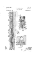
- FIG. 7 Yisla small 'scale sectional view showing the instrument mounted ina special sub in a drill string;
- FIG. '8 is a fragmentary sectional view illustrating aruseful modiiica-tion of the signal-generating plunger
- the sub Ill diters from a conventional sub or drill collar in being enlarged in internal the invention automatically provides a deviation measurement every time the pumps are started Vup after any pause such as a pause for the addition of a length of drill pipe and the cost, if any, in additional .down time is merely a pause vof less than l5 seconds when the mud pumps are stopped.
- the ring l2 backs against a shoulder 15 ⁇ of the housing H and is retained by a snap ring 16.
- the two radial projections 14 are attached by screws 18 to a cylinder 26 that Vlits snugly inside the sub l@ and extends above the upper end or the housing
- the Vcylinder 20 isl formed vwith a ⁇ series of requally Y spaced restrictions in the form of rings For inner circuma relief valve to prevent a destructive rise in the pressure pendulum; to provide a readily removable and replaceable valve assembly for the instrument; and to make the inner annular stop shoulder of lthe plunger separable from the plunger proper to prevent overstressing of the stop tube and its selective stop elements.
- FIG. l is a simplified axial sectional view ⁇ of two successive longitudinal sections vof the presently preferred embodiment'of the invention.
- FIG. 2 is a similarrview of the remaining three successive longitudinal sections of the instrument
- FIG. 3 is a similar simplied view in two sections Vof the liquid in the instrument; to provide interchangeable sets of rings to serve as stop shouldersior the'.
- FIG. 4 is an enlarged sectional view of a removable cartridge that provides a time delay valve together with a dashpot means in series therewith;
- FIG. 5 is an axial sectionalview of an assembly ⁇ unit v.that includes the removable Vcartridge ⁇ of FIG. 4 together with other removable cartridges includingV a relief valve cartridge that is shown in section;
- FIG. 6 is anend view of 4the assembly unit shown in FIG. 5;
- a plunger that is generally designated by the letter l protrudes axially from the upper end of the housing HV and is formed with an enlargement or head 24vwhich traverses the series of restrictions Z2 forV cooperation therewith to generate the deviation-indicating Y
- there are seven restrictions whichV are correspondingly numbered in FIG. l beginning with the lowermost restriction nearest the fully retracted position of the plunger Yhead 24. 1
- the lower end of the housing H is also concentrically supported inside the sub I0, for example by a second pair of diametricallyopposite radial spacer projections 14a as indicated in FIG. 7
- the instrument housing, H forms with the surrounding sub itl an ample passage- ⁇ way for the drilling lluid.
- instrumentA liquid which is subjected to the hydrostatic pressure of the column ofV drilling fluid in the drill string.
- the upper end of the instrument housing is sealed by an. fO-ring 25 (FIG. l) embracing the plunger P and the. opposite or lower end of thel instrument housing is closed bytamovable wall'in the form of a bag-shaped diaphragm 26,.
- the diaphragm 25 correspondingly moves Vinward and ⁇ outward in accord with the displacement of the instrument liquid.
- the housing H is formed with a relatively large axial bore 28 for the plunger P.
- the upper end of the bore 2S is reduced in diameter to guide the plunger P and to form an inner annular stop shoulder 3? for abutment by a snap ring 32 on the plunger (middle section of FIG. 2) to determine the maximum upward extension of the plunger.
- the plunger P is further guided by an integral guide collar 34 that slides in the axial bore 2S and is formed with a longitudinal groove 3S for displacement fiow of the instrument liquid.
- a plunger spring 36 surrounds the lower end of the plunger and acts in compression between the guide collar 34 and the bottom end of the axial bore 28 to urge the plunger towards its fully extended position.
- the plunger P is formed with a relatively large axial bore 38 which extends upward from the lower ⁇ end of the plunger and terminates near the plunger head 24 as shown in the lower section of FIG. 1.
- a coding rod is slidingly mounted both in the stop tube 4t) and its base portion 42 and pivotally carries at its lower end a suitable deviation-detecting pendulum 44.
- the coding rod C together With the pendulum 44 follows the initial upward extension movement of the plunger P and for this purpose what may be termed a pendulum lift spring 4S acts in compression between an annular shoulder 46 of the coding rod and an inner circumferential shoulder 4S in the base portion 42 of the stop tube.
- the coding rod C is formed with an enlargement 59 at its upper end (lower section FIG. l) and is formed with a piston-like enlargement 'S2 at its lower end (lower section FIG. 2).
- the coding rod C In the normal position of the parts with the plunger P fully retracted and the pendulum 44 at its lowermost position, the coding rod C is held down by a short coil spring 54 that has a higher spring rate than the pendulum lift spring 45.
- the spring S4 acts in compression between the upper coding rod enlargement 59 and the upper end of the axial bore 38 of the plunger.
- the lower enlargement 52 of the coding rod C cooperates with a radial shoulder 55 in the base portion 42 of the stop tube 4t) to limit the upward movement of the coding rod and the associated pendulum 44.
- the pendulum 44 hangs in a pendulum chamber 56 and is formed with a conical nose which normally rests in a conical seat 60 at the lower end of the pendulum chamber, the pendulum being normally pressed into the seat by the force of the short coil spring 54.
- the enlargement Sti of the coding rod 40 is provided with a longitudinal peripheral groove 62 and the upper portion of the axial bore 3S of the plunger is enlarged to provide an annular space around the stop tube 4t). This annular space terminates at an inner annular tapered stop shoulder 64 (middle section FIG. 2) formed in the axial bore 33.
- At least one radial bore 65 in the plunger P adjacent the tapered stop shoulder 64 places the axial bore 3S of the plunger in communication with the axial bore 2S of the instrument housing H.
- At least one radial bore 66 (lower section of FIG. 2) permits displacement flow into and out of the interior of the base portion 42 of the stop tube and at least one longitudinal bore 68 permits displacement fiow between the axial bore 28 of the instrument housing and the pendulum chamber 56.
- the pendulum chamber 56 communicates with a filter chamber 72 which in turn communicates with a second filter chamber 74 that is open to the diaphragm chamber 70.
- the two iilter chambers 72 and 74 are spanned by replaceable filter disks 75.
- the pendulum chamber 56 is connected with the filter chamber 72 by an axial bore 76 in the conical seat 60 and additionally by at least one eccentrically positioned longitudinal bore 78.
- the filter chamber 72 communicates with the filter chamber 74 through a check valve, generally designated S0, through a relief valve, generally designated 82, and also through a time delay valve, generally designated 84, that is in parallel with the relief Valve.
- the time delay valve 84 is in series with orifice means in a dashpot chamber 85.
- the upper end of the pendulum 44 is chamfered to seat normally in a tapered recess 86 in the lower end of the coding rod C.
- the upper end of the pendulum 44 is formed with a bail 8S which extends through a bail 90 that is embedded in the coding rod, the two bails cooperating to provide a lost motion connection that permits the pendulum either to seat in the tapered recess 3d or to hang from the coding rod in a sensitive pivotal manner.
- the pendulum 44 is formed with a sharp upwardly directed circumferential shoulder 92 for selective engagement with six inner annular stop shoulders in the pendulum chamber that correspond with six of the seven restriction rings 22 that cooperate with the plunger head 24 for the creation of deviation-indicating signals. If the pendulum passes all of the annular stop shoulders it reaches a limit position corresponding to the lowermost restriction ring 22.
- a feature of this embodiment of the invention is the fact that the series of six stop shoulders are formed by a replaceable stack of six stop rings 93a-93f.
- the stop tube 40 has six equally spaced sets of radial apertures to house six corresponding sets of stop elements in the form of six sets of small hard metal balls, designated respectively 102g, li'iZb, 192e, 1.02ct', 162e, and 1021, for cooperation selectively with the previously mentioned tapered inner stop shoulder 64 of the plunger P (middle section of FIG. 2).
- Normally all of the stop balls 10241-1021 are free to retract to radially inward positions within the outside diameter of the stop tube 40 to permit the annular stop shoulder 64 of the plunger P to pass.
- the coding rod C has six circumferential enlargements designated NMa-10412 respectively, for cooperation with the six sets of stop balls 1Ghz-1021*, each enlargement being formed with a circumferential groove to register with the radial set of balls.
- the coding rod enlargement 104 shown in the middle section of FIG. 2 moves into register with the set of stop balls 102e to shift the stop balls radially outward to their effective positions for engagement by the inner tapered shoulder 64 of the plunger P to stop the plunger at a position placing the plunger head 24 between the two restriction rings 22 that are numbered 1 and 2. Consequently the subsequent retraction of the plunger P carries the plunger head 24 past only one restriction ring to create only one deviation-indicating signal.
- the coding rod enlargement 104 moves into register with the stop balls 102b to causethe plunger head 24 to comey Y to rest between the restriction'rings numbered-2 and 3 to result in two signals when the plunger is subsequently retracted.
- FIG. 3 shows the circumferential shoulder 92 Vofthe pendulum stopped in the stop rin-g 553i by the-stop shoulder 110 and shows the coding rod enlargement 104fcorrespondingly moved into register with the set of stop balls 102]I
- the inner annular stop shoulder 64 of the plungery P is shown stopped by the setof balls 1021 to result in six signals.
- thev coding rod C shifts onestep less than its maximum distance to cause the set of stoprballs 102b to be made effective by the coding rod enlargement 104b for blocking the inner .tapered stop'shoulder 64 of the plunger P,-the circumferential locking groove 112 registers with the set of locking balls 102a, permitting the locking balls 19251 to take their inner ineffective positions within the outer diameter ofthe stop tube 40.
- the inner tapered stop shoulder 64 of the plunger P passes 4beyond the inwardly retracted set of stop balls 102a, it traps the stop balls in the circumferential locking groove 112 whereupon the trapped locking balls cooperate with the corresponding apertures inthe stop tube 40to lock the coding rod in position.
- the circumferential locking groove 113 registers with the lockinglballs 102a when the coding rod Y eniargementlttlc registers with the stop balls 102C; the
- circumferential locking fgroove114 registers with the locking balls 102a when the coding Vtube enlargement 104d registers with the set of stop balls 102d; the circumferential locking groove ⁇ 115 registers with the set of locking balls 1020 when the Vcoding rod enlargement 104e registerswith the locking balls 102e; andthe circumferential locking groove 11e registers with the set of locking balls 102e when thev coding rod enlargement 104i registers'with the set of lockingrballs 1021V
- the circumferential shoulder 92 of the pendulum engages the responding set of stop balls 102a-102f is indicated by the distance A plus a succession of steps which correspond to the distances between the successive stop shoulders of l the stop rings 93a-93f.
- plunger P comprises the Vcoding rodf enlargement 104a andlsix circumferential locking grooves 112-117 adjacent this enlargement.
- tension of the plunger P is on the order'of l2 inches and the coding rod C is locked by the time the plunger extends only 2 inches from its normal retracted position.
- the previously mentioned three Valves 80, 82 and 84 are in the form of cartridge-like units ⁇ that are removably/mounted in a cylindrical metal block shown in FIGS. 5 and 6.
- the cylindrical metal block 120 in turn is mounted in the instrument housingH in a removable manner and is circumferentially grooved to receive an O-ring 122.
- the check valve S0 is in acartridge 124; the relief valve 82 is in a cartridge and the time delay valve 84 together with vthe previously mentioned dash-pot means is in a vthird ycartridge 126.
- the cartridge 124 for the check valve 80 is a one-piece tubular body which provides a fluid passage of the configuration shown in the lower section of FIG. 2.
- the liuid passage forms/a seat 135 for a gravity biased valve ball 13'6.
- the Vcartridge 126 that provides the time delay valve tte-'and the associated ⁇ dashpot means may be of the construction shown in FIG. 4.
- the flow passage through the cartridge 126 forms a seat 140 for a valve ball 142.
- the valve ball abuts a spacer pin 143 and is urged into the seat by a suitable spring 144.
- the fluid passage is enlarged to receive a stack of recessed disks 145 which serve as partitions to form a succession of chambers 146.
- Each of the disks 145 is provided with a small orifice 143 to permit the instrument liquid to flow through the chambers in series, each of the orifices 148 being offset from the adjacent orifices.
- the stack of disks 145 is secured by a bushing 150 that threads into the end of the cartridge and is secured by the previously mentioned diametrical pin 134.
- Each of the orifices 148 is large enough to pass with ease foreign particles of the size that may normally be found in the liquid in an instrument of this type.
- Each of the orifices 148 taken alone would not provide the retarding effect on the instrument liquid that is required for the desired dashpot action but since the orifices are in series the net effect is to retard the instrument liquid to the same degree as a single orifice that would be too small to pass the foreign particles freely.
- the cartridge 125 that provides the relief valve 82 may be of the construction shown in FlG. 5.
- the fluid passage through the cartridge provides a seat 152 for a valve ball 154.
- a iioating disk 155 is under pressure from a valve spring 156 and is provided with an axial pin 158 which presses against the valve ball 154 to urge the valve ball into the seat.
- FIG. l together with FIG. 2 shows the normal kpositions of the working parts of the drift indicator, i.e.,
- the force of the downwardly flowing mud stream against the plunger head 2d keeps the plunger P in its normal fully retracted position in opposition to the pressure exerted by the plunger spring 36, the pendulum lift spring 45 and the short spring 54.
- the check valve Si), the relief valve 82, and the time delay valve 84 are all closed with the diaphragm chamber 70 filled to maximum with the instrument liquid.
- the pendulum is under compression by spring pressure with the bottom end of the pendulum in the seat 60 and with the upper end of the pendulum in the recess 86.
- both the drilling operation and the operation of the mud pumps may be stopped for approximately one minute any time it is desired to cause the deviation detector to go through its cycle of operation.
- the deviation detector will go through its operating cycle automatically Whenever the drilling operation is interrupted for the addition of a new length of drill pipe to the string.
- the advantage of the invention in this regard may be appreciated by describing the manner in which the operating cycle is carried out automatically whenever drilling is interrupted for the addition of a length of drill pipe to the string.
- both the drilling operation and the operation of the mud pumps are stopped.
- the mud pumps are stopped it is necessary to wait until the mud stream is completely decelerated before the connection between the mud pumps and the drill string is broken. Otherwise, mud would spurt from the broken connection. Consequently, the drilling crew must wait for a short period of time after the mud pumps stop before proceeding with the task of adding the length of drill pipe. Within this brief period of time the following sequence of operations occurs automatically.
- the reduced impact force against the plunger head 24 permits the plunger spring 36 to start the upward extension movement of the plunger P.
- the check valve Si) opens freely to permit the displacement of the instru- 10 ment liquid from the diaphragm chamber '70 through the pendulum chamber 56 into the upper fluid passages of the instrument as required for the extension movement of the plunger.
- the upward movement of the pendulum 44 is stopped by engagement of the circumferential shoulder 92 of the pendulum with one of the stop rings 93a-93f if the deviation of the bore hole from vertical is greater than 1/2". lf the bore hole deviation from vertical is less than 1/2 the circumferential shoulder 92 of the pendulum is carried upward the maximum distance to come to rest inside the uppermost and smallest stop ring 93a.
- the resulting position of the coding rod causes one of the sets of stop balls lima-192i to expand radially outward into the path of the upwardly advancing tapered inner stop shoulder 64 of the plunger P to stop the plunger. If the pendulum catches on the first lowest stop shoulder, none of the sets of stop balls 1tl2a-102f is expanded and the plunger P continues to its upper limit position at which the stop ring 32 of the plunger meets the stop shoulder 3@ of the instrument housing H.
- the tapered inner stop shoulder 64 of the plunger P is stopped by the first set of stop balls 102e to indicate that the deviation of the bore hole from vertical is less than 1/i the plunger P acting under the pressure of the plunger spring 36 cooperates with the set of stop balls 102m to lock the coding rod C in place and thus make the coding rod immune to subsequent shocks that may occur in the course of adding the new string of drill pipe. If the deviation of the well bore from vertical is greater than 1/2 however, the upward movement of the coding rod C will terminate before the tapered inner shoulder 64 of the plunger P reaches the first set of stop balls 1tl2a and the stop balls 102a will register with one of the circumferential locking grooves 112-117 of the coding rod C.
- the upward extension movement of the plunger P is accelerated by the rapidly dropping velocity of the drilling fluid. It is also important to note thatthe whole sequence that culminates in the locking operation occurs in an initial portion of the upward movement of the plunger that is only a fraction of the maximum range of upward movement of the plunger. In addition, this initial portion of the upward extension movement o f the plunger P is appreciably boosted briefly by the relatively strong spring 54 and in a more prolonged manner by the pendulum lift spring 45. Consequently the whole sequence of operations to the point of locking the coding rod C is completed in less than l5 seconds.
- the plungerP-l is of 148 until pressure above the time delay valve is Vsufficienti to overcome the closing force exerted by spring 144.-
- the ward to seatV partially in an inner circumferential groove 1 ,64-in'the plunger proper and partially in an outer circumferential groove 165m the sleeve 16).
- the downward movement of the plunger P gives rise to brief periods of restricted'ilow ot the drilling fluid as ⁇ i the plunger head 24 passes through the restriction rings 22 that lie, between the selected extended position ofthe plunger head and the fully retracted lposition ofthe plunger head.
- Each occurrence of restricted flow creates a sud den rise in pressure in the mud column.
- Eachl pressure rise travels to the'suriaceV in the form of a wave at sonic velocity .thatV can readily be detected by observing Va suitable pressure gaugeV or by employing any other suitable',
- the invention permits the pendulum to be of relatively delicate construction as required for high sensitivity. If the impact force against the plunger to an undulylarge force'in the'direc'tion of extension of the plunger, the detent ring 162 is cammed inward into the circumferentialr groove 165 of thez sleeve to permit the,V plunger properto extend' without the sleeve 16).
- detent spring is rst cammed inward into they circumferential groove '165 of the sleeve and then expands outward into' its normal position in the circumferential groove 164 Y in the plunger.
- the plunger 'Pelis made in ,two separable parts comprising a lowerV section,y generally designated 179, and an upper section, ,generally designated 172.
- the lower section 17e provides the taperedstop'shoulder 64b for cooperation ⁇ with the Astop balls.
- the upper' plunger section ll'izin cludes the usualguide collar 34a and carries the v.usual plunger headda.
- the lower plunger section 17? carries a tubular spring seat174 that is formed with a radial Vilange 175 ⁇ to receive the lifting pressure of the usual plunger spring 36.
- FIGS. 8 to l1 indicate various ways in which the construction of the instrument shown in FIGS. l to 6 may be vmodified by making the plunger P in twosections which separate under an excessive tension load on the plunger to prevent damage to the mechanism thatisA employed to limit the extension ofthe plunger selectively' in preparatIon for measuringdeviation.
- the need for such a modification occurs in the event that the lowering/0f the drill string into the Well bore Vreverses the flow of the drill stream violently upward to tend to lift theV plunger head24.
- FIG. 8 shows how theplungerP may be madein ⁇ two A light spring 176 having a substantially smallers'pring ratethan the spring 36 acts in compression between the guide collar 34a and an upper stop shouldery 173 formed by the instrument housing H.
- the light spring 176 urges the guide collar vv34a against the flange 175 of -the spring seat member 174 to maintain the two plunger sections in the desired assembled relationship. If an excessive ylifting force acts on .the plunger head 24a, however, the upper' plunger section separates from the lower plunger section against the opposition of the relatively light spring 176. VIt is apparent-therefore that by virtue of this arrangement the pressure of the inner annular stop'shoulder 64.01? the plunger against a set of stop balls 1G2a102f can never exceed the pressure Vexerted by the main plunger spring 36. 1 Y
- the plunger P-3 isagainmade in two separate sections comprising a lower section, generally'designated lthand an upper section,
- Therlower plunger section 180 plunger section 1&2 has the usual guide collar 34h and telescoping sections that may normally be held together Y the previously described construction except that the tapered inner annular stop shoulder 64a of theplunger iS the end of a sleeve160 that slidingly telescopes into the plunger.
- the sleeve 16) is normally united with the plunger proper by a detent spring 162 in the form of a split ring.
- the detent spring 162 is biased radially outthe usual exterior head Zeb.
- a relatively light spring 176e acts against the guide collar, 34h to urge the two plunger sections ltogether whereby the two sections ⁇ of the plunger function in the same manner as the two plunger Vsections of FIG. 9.
- FIG. 10 also illustrates the fact ythat the pendulum 44a maybe directly mounted on the lower end of the lower' plunger section 186 since the'capability of the plunger to separate in the manner described makes it impossible for the pendulum to be subjected to a greater loadthan the force exerted by theplunger spring 36.
- Such a construction does not have ⁇ the advantage of reversing the sequence of the'signals and requires thatV the overall length ofV the instrument be increased, but the con- .structionis relatively simple and may be employed ad vantageouslyin someV instances.
- FIG. ll illustrates another manner in which a plunger P-4 may comprise two separate sections.
- the lower section 19t forms at its upper end a cup-shaped member 192 and the upper plunger section 194 telescopically seats in this cup-shaped member.
- the usual plunger spring 36 presses upward against the cup-shaped member 192 and the usual light spring 17611 presses downward against the guide collar 34C to urge the upper plunger section into the cup-shaped member.
- a series of balls 195 interposed between the guide collar 34C and the cup-shaped member have liberal clearance to avoid interfering with the movements of the upper plunger section 194.
- the lower end portion of the upper plunger section 194 that seats in the cup-shaped member 192 is formed with a conical enlargement 196 that is capable of camming the balls 195 radially outward into locking engagement with the surrounding instrument housing H.
- a signalling drift indicator for use in a downward stream of drilling tluid in a drill string in a well bore wherein the drift indicator has a housing for positioning in the drill string longitudinally thereof, a plunger protruding longitudinally from the housing for extension and retraction relative thereto to generate a series of spaced signals by downward movement in response to force by the stream of drilling fluid, and means to urge the plunger upward
- a signalling drift indicator for use in a stream of drilling fluid in a drill string in a well bore wherein the drift indicator has a housing for positioning in the drill string longitudinally thereof, a plunger protruding longitudinally from the housing for extension and retraction relative thereto to generate signals by movement in response to force by the stream of drilling fluid, and means to urge the plunger in the direction counter to the direction of the stream of drilling fluid
- a combination as set forth in claim 2 in which the return movement of the plunger in the direction of the Stream of drilling fluid creates a series of spaced signals; in which said means responsive to the relative inclination of the housing limits the movement of the pendulum directly as the inclination of the housing; and in which said means controlled by the pendulum stops the movement of the plunger in the direction counter to the stream of drilling fluid at positions corresponding inversely to the positions of the pendulum whereby the number of signals generated by retraction of the plunger varies directly with the relative inclination of the housing.
- a signalling drift indicator for use in a downward stream of drilling fluid in a drill string in a well bore
- the drift indicator has a housing for positioning in the drill string longitudinally thereof, a plunger protruding longitudinally from the housing to generate signals by downward movement in response to force by the stream of drilling fluid, and means to move the plunger upward from a normal position when the plunger is not subjected to force by the stream of drilling fluid, the combination therewith of: a pendulum in said housing separate from the plunger to move over a range substantially shorter than the range of movement of the plunger in response to an initial portion of the upward movement of the plunger; means responsive to the inclination of the housing relative to the pendulum to limit the movement of the pendulum over said short range in accordance with different degrees of inclination of the housing; a plurality of normally ineffective stops for said plunger distributed along the range of movement of the plunger and corresponding to the different inclination-indicating positions of the pendulum; and means extending along said series of stops and
- a combination as set forth in claim 4 in which the downward movement of the plunger creates a series of spaced signals; in which said means responsive to the relative inclination of the housing limits the movement of the pendulum directly as the inclination of the housing; and in which said means movable with the pendulum makes the stops effective selectively to stop the upward movement of the plunger at positions varying inversely with the inclination-indicating positions of the pendulum whereby the number of signals generated by downward movement of the plunger varies directly with the relative inclination of the housing.
- a signalling drift indicator for use in a downward stream of drilling fluid in a drill string in a well bore wherein the drift indicator has a housing for positioning in the drill string longitudinally thereof, a plunger protruding longitudinally from the housing to generate signals by downward movement in response to force by the stream of drilling fluid, and means to move the plunger upward when the plunger is not subjected to the force of the stream of drilling fluid
- a combination as Vset forth in claim 6 whichincludes means responsive tol'an initial portion of theupwar -t said Vhousing inside said annular stop shoulder and exl tending along the 'path of movement ofthe annular stop shoulder; stop .elements mounted in Vsaid stop tube for movement between normal positions and effective positions in thefpath' of said annular stop shoulder for cooperationy therewith. to stop the upward movement of theplunger; arid a'coding rod-extending into said stop tubeV and Vmovablewith the penlulum to shift said stop movement ofthe plunger to lock said coding means in Y its selected position afterthe pendulum is stopped theref by to malte the coding means immune to shocks whereby,Y
- the drill string may be manipulated immediately after an initial Iportion of the upward movement of the plunger without changing the signals represented by the stopped position ⁇ of the rpendulum even if the manipulation of the stream of drillingtiuid, and means to move the plunger upward when the plunger is not subjected to the force of v the stream of drilling fluid, the combination of:V a pendu-'f lum in said housing movable longitudinally in response' elements froml their. normall positions to their effective positions selectively in accord with the limit positions of the pendulum.
- ⁇ a signalling drift indicator foruse in a downwardstream of drilling fluid in a drill string in a Vwell bore
- the indicator has a housing ⁇ for positioning Y inthe'drill string longitudinally thereof, a plunger protruding longitudinally from the housing to generate a series of signals bydownward movement in response to to limit the movement of the pendulumdirectly as the inv clination ofthe housing; a series of normally ineffective stop means distributed along the range of movement of the plunger to stop the rupward movement of the plunger selectivelyat points corresponding to different degrees of inclination of the housing'to result in a corresponding number of signals when the plunger is subsequently returned downward by the stream of drilling fluid; coding means extendingY along said series'of stop means and movable'b'y the pendulum to make the stop means.etectiveselectively 1n accord with the degree to which the pendulum movement is limited; and; means responsive to the extension movement of said plunger to lockl said coding means in' position after the
- VA combination as set forth in claim S in which saidl plunger is divided into two separate sections, one section to generateA the signals and the other ⁇ section to be engaged by and stopped selectively by said series of stop means; and in which said sections are separable whereby said two sections separate under a separation load to avoid imposing a damaging load on the selected stop means.
- a signalling drift indicator for use in a downward stream of drilling fluid in a rdrill string in a well bore
- the kdrift indicator has a housing for positioning in the drill string longitudinally thereof, a plunger force by the stream of drilling liuid, means to move the plunger upward when it is not subjected to the force of having a movable magnitude without clogging,
- said housing being Yiilled with a liquid and Ywail to vpermit displacement flow of the liquid in the housing inresponse to movementof the plunger whereby the combined volume of the housing and the protruding vportion'ofthe plunger is constant, the combination therewith of orifice means to retard the displacement ilow ofthe liquidjin the housing thereby to retard the signal-generating retraction movement of the plunger when tlow of the stream of drilling fluid is initiated, said orifice means comprising: a series of chainbers Iseparated by spaced walls with orifices in the walls for flow of the liquidv through the series of'chambers in sequence, said orifices being of liberal dimensions fory passage of iinely divided foreign particles of a given thetotal retarding effect of Y the
- a combination as set for-thin claim 13 which in- Y Vcludes a spring-loaded valve in series withsaid chambers to yieldingly oppose the displacement flow of the liquid through the series of chambers thereby to delay the downprotruding longitudinally from the housing toV generate signals by downward movement in response to force by the stream of4 drilling fluid, and means to move the tudinally in response to the upward movement ofthe plunger; means responsive to inclination of the housing relative to the pendulum to limit the movement of the pendulum directly as Vthe inclination of the housing;
- annular stop shoulder connected with said plunger for movement therewith; a stop tube iixedly mounted in ward movement of the plunger until the rate of ilow of Ythe drilling iuid rises to a predetermined magnitude.
- Vl5. Acombination as -set forthin claim 13 which includes a by-pass in parallel with said series of chambers; and which includes a spring-loaded relief valve normally closing saidV by-pass and yieldingly opposing the displacement flow caused by downward movement of the plunger,
- a signalling drift indicator for use'in a down- Wardstream of drilling fluid in a drill string in a well bore
- the indicator has a housing for positioning in the drill string longitudinally thereof, a plunger protruding longitudinally from the housing to generate a series of signals by downward movement in response to force by the stream of drilling fluid, means to move the plunger upward when it is not subjected to the force of f' the drilling stream, a gravity-responsive deviation detector to limit the upward movement of the plunger in accord with the degree of deviation of the well bore from vertical, said housing being iilledwith a liquid and having iiuid is initiated, the combination therewith of: by-pass means in parallel with said orifice means, and a springloaded relief valve normally closing said by-pass and yieldingly opposing the displacement iiow caused by downward movement of the plunger', said relief valve being normally closed and yielding to a predetermined high iluid pressure to keep the pressure of the liquid in the housing from rising to a destructive magnitude when the force of
- a signalling drift indicator for use in a downward stream of drilling fluid in a drill string in a well bore
- the indicator has a housing for positioning in the drill string longitudinally thereof, a plunger protruding longitudinally from the housing to generate a series of signals by downward movement in response to force by the stream of drilling liuid, means to move the plunger upward when it is not subjected to the force of the stream of drilling iiuid, and a gravity-responsive deviation-detector to limit the upward movement of the plunger in accord with the degree of deviation of the well bore from vertical
- said housing being filled with a liquid and having a movable wall to permit displacement flow of the liquid in the housing in response to movement of the plunger whereby the combined volume of the housing and the exposed portion of the plunger is constant, the combination therewith of means to prevent initiation of the downward movement of the plunger for a substantial period of time after liow of the downward stream of drilling fluid is initiated thereby to pro-vide a time interval for
- a combination as set forth in claim 18 which includes: a lay-pass in parallel with said delay means; and a spring-loaded relief valve normally closing said bypass and yicldingly opposing the displacement flow caused by downward movement of the plunger, said relief valve yielding to a predetermined high iiuid pressure to keep ythe pressure of the liquid in the housing from rising to a destructive magnitude when the force of the stream of drilling fluid on the plunger rises excessively.
- a signalling drift indicator for use in a down- ⁇ ward stream of drilling fluid in a drill string in a well bore wherein the indicator has a housing for positioning in the drill string longitudinally thereof, a plunger protruding longitudinally from the housing to generate a series of signals in response to downward movement of the plunger by the force of the stream of drilling huid,
- rvme ans to move the plunger upward from a normal posithe liquid in the housing in response to movement of the plunger whereby the combined volume of the housing and the protruding portion of the plunger is constant, the combination therewith of: means to retard the displacement flow of the liquid in the housing when the flow of the stream of drilling fluid is initiated thereby to retard the downward movement of the plunger; a by-pass in parallel with said retarding means; and a spring-loaded relief valve normally closing said by-pass and yieldingly opposing the displacement flow caused by downward movement of the plunger, said relief valve yielding to a predetermined relatively high liuid pressure to keep the pressure of the liquid in the housing from rising to a destructive magnitude when the force of the stream of drilling fluid on the plunger rises excessively.
- a signalling drift indicator for use in a downward stream of drilling fluid in a drill string in a well bore
- the drift indicator has a housing for positioning in the drill string longitudinally thereof, a plunger protruding longitudinally from the housing to generate a series of spaced signals by downward movement iny response to force by the stream of drilling uid, and means to move the plunger upward when the plunger is not subjected to the force of the stream of drilling fluid, the combination therewith of: a pendulum in said housing structurally separate from said plunger; a lift spring urging said pendulum upward against the plunger to cause the pendulum to follow the upward movement of the plunger; a series of stops to limit the upward movement of the pendulum in accord with the inclination of said housing from vertical, the range of elfectiveness of said stops being substantially shorter than the maximum range of extension of the plunger whereby the pendulum follows only a small initial portion of the upward movement of the plunger; and means controlled by the relatively short movements of the pendulum in
- a combination as set forth in claim 21 which includes means to lock the pendulum in its stopped position in response to the upward movement of the plunger beyond said initial portion of its upward movement.
- a plunger assembly for use in a drift indicator in a downward stream of drilling iiuid in a drill string in a well bore, wherein the drift indicator has a housing for positioning in the drill string longitudinally thereof, said plunger assembly protrudes longitudinally from the housing for extension and retraction relative thereto to generate a series of signals by downward movement in response to force by the stream of drilling iiuid, means to urge the plunger assembly upward when said force is not effective, and means to limit the upward movement of the plunger assembly in accordance with the inclination of the housing fromv vertical thereby to control the signals, said plunger assembly comprising: a first section controlled by said limiting means; a second section protruding from the housing to generate signals; and yielding means to normally hold the two sections together and to yield -in response to a separation force of a predetermined magnitude for separation of the two sections in response to an excessive upward load on the second section to prevent transmission of the excessive load to said limiting means.
- a plunger assembly as set forth in claim 25 which includes means movable with the second section to engage said housing to immobilize the second section, said immobilizing means being responsive to relatively slight spra'tion 'of the two sections thereby 'to limit l ⁇ bedisqressure bf'th'endrilling 'uid to prevent displa'eementbf 'tlequid Yin the"housing'whe1nthezpressre of ⁇ time dilflirrg fluid is relatively 110W nd lto. permit 4such'displacriient 'whenjthe prssureof the r ⁇ 'drilling u'id 'is relatively Ahigh "auge-0?.
Description
April 6, 1965 R. L. ALDI-:R ETAL 3,176,407
DRIFT INDICATOR Filed March 11, 1960 5 Sheets-Sheet l April 6, 1965 R. ALDER ETAL DRIFT INDICATOR 5 Sheets-Sheet 2 Filed March 1l, 1960 Koi wmf
R. L. ALDER ETAL DRIFT INDICATOR 5 Sheets-Shea?l 3 \\\\\\\\\\\\\\\\\\\\\\\\\\\\\N\\\Mvmw yV55/56.5@5x5/f5.5 i?? April 6, 1965 Filed March 11. 1960 ,www
April 6, 1965 R. l.. ALDER ETAL DRIFT INDICATOR 5 Sheets-Sheet 4 Filed March ll. 1960 nu u m u M w m m S Aprll 6, 1965 R, ALDER ETAL. 3,176,407
DRIFT INDICATOR Filed March 11. 1960 5 sheets-sheet s .b im M M Mwuhhll..-
f77/ofwel@ United States Patent O 3,176,407 DRHIFT lNDlCATGR Robert Lee Alder, La Canada, and Paul Si. Arnerieh,
Pasadena, Calif., assignors to Varney Engineering Corporation, El Segundo, Calif., a corporation of California Filed Mar. 11, 1969, Ser. No. llill 27 Claims. (Ci. 33--2tl5) This invention relates to a signalling device for use in drilling a well bore to indicate deviations of the well bore from vertical. The invention is of the general character disclosed in the Varney Patents 2,329,732; 2,435,934; and 2,762,132, which disclosures are hereby incorporated in the present disclosure by reference.
The deviation signals are produced by periodically restricting the flow of the drilling fluid to create a succession of pulses of pressure in the drilling stream, the number of pulses varying in accord with the degree of deviation. The pressure pulses may be readily detected and, of course, may be amplitied if desired.
The device typically comprises a liquid-filled instrument casing or housing and a plunger that tends to be extended longitudinally upward from the housing by spring action. The plunger has a head or enlargement that traverses a series of annular restrictions in the drill pipe to produce the series of signals. The instrument housing has a movable wall, for example a diaphragm, which permits displacement of the confined instrument liquid so that the combined volume of the housing and the exposed portion of the plunger remains constant throughout the operation of the device.
When the downward flow of drilling iluid is stopped, the plunger extends along the series of restrictions to whatever degree is permitted by a pendulum which moves along a series of graduated stop shoulders. When the ow of drilling iluid is resumed the force of the stream against the plunger head drives the plunger slowly back to its normal retracted position with consequent creation of the deviation signals in accord with the stopped position of the plunger.
Heretofore the number of signals has decreased with increasing deviations from vertical because the pendulum moves upward past a series of annular shoulders that are necessarily of progressively decreased diameter. The nearer to vertical the instrument housing, the greater the upward travel of the pendulum together with the plunger that is controlled by the pendulum.
One important object of the present invention is to reverse this situation to cause the number of signals to vary directly as the deviation of the bore hole from vertical. This reversal lessens the burden of interpreting the signals in terms of deviation. In the presently preferred embodiment of the invention, for example, each of the successive stop shoulders for the pendulum represents onehalf degree of deviation from vertical. To lind the actual number of degrees of deviation of the bore hole from vertical, the operator merely mentally divides the number of signals by two.
Heretofore the instrument housing has been dimensioned to lit into a conventional drill collar or sub. It is now contemplated that the instrument housing will be increased in diameter and mounted in a special sub that is, of course, of the same outside diameter as a conventional sub. This change is desirable to increase the size of passage through which the drilling liuid may llow past the instrument in a drill string of a given nominal diameter. The special sub should be relatively short for a number of reasons and especially because of the cost of fabricating such a special sub. A second object of the invention, therefore, is to shorten the length of instrument case without, however, shortening the range of the signal-creating movement of the plunger.
ice
A third object of the present invention is to avoid an excessive tension load on the pendulum. It has been found that in constructions heretofore used the pendulum fmechanism may be subjected to excessive strain when violent reverse flow of the drilling iluid is experienced during :the lowering of the drill string in the bore hole. The reverse iiow subjects the plunger to excessive extension force which is transmitted to the pendulum.
A fourth object of the invention is to minimize the down time required to derive a deviation measurement. To take time out just to stop the mud pumps and to stop the rotation of the bit to permit the spring-actuated extension Iof the instrument plunger in preparation for deriving the measurement involves an undesirable reduction of the productive drilling time. In many instances, moreover, the formation that is being drilled is such that it may slump into the bore hole, with consequent danger of sticking the drill string, when the mud pumps are stopped and at the same time rotation of the drill string is stopped. Such a condition is necessarily risked periodically for the purpose of adding a length of drill pipe to the string but drillers are reluctant to prolong the risk for the sole purpose of obtaining a deviation reading. Heretofore the added down time required for operation of the deviation detector has been approximately two minutes. The present invention reduces the additional down time to a period on the order of 15 seconds or less whenever a length of drill pipe is added.
These four objects of the invention are made possible by a new arrangement for operatively relating the pendulum to the signal-creating plunger. Heretofore the pendulum has been directly connected to the plunger. A basic feature Vof the preferred practice of the present invention is that the pendulum is structurally separate from the plunger and controls a series of stop elements which, in turn, limit the extension movement of the plunger.
In the present embodiment of the invention, what may be termed a stationary stop tube telescopes into the lower or inner end of the signal-creating plunger and provides a series of spaced stop elements which cooperate selectively with an inner annular stop shoulder of the plunger. The pendulum is connected to what may be termed a coding rod which slidingly telescopes into the xed stop tube. In response to the movement of the pendulum that terminates in accord with the deviation of the bore hole, the coding rod shifts in the stop tube to make the stop elements eiective selectively in accord with the stopped positions of the pendulum.
The first object of providing a series of signals that varies directly with .the degree of deviation is accomplished by arranging for the coding rod to operate the stop elements in the opposite order to the sequence of the stop shoulders 4that are traversed by the pendulum. Since inherently the magnitude of move-ment of the pendulum varies inversely with the deviation from Vertical, the reversal in the order of the opera-tion of lthe stop elements causes the range 'of responsive movement of .the plunger to vary directly with the deviation `of the bore hole. Thus, the longer the movement of the -controlling pendulum, the shorter the movement of the signalcreating plunger.
The second object of shortening the length of the instrument case is accomplished by reducing the range of movement of the pendulum. The structural separation of the pendulum from the signal-creating plunger makes this cha-nge possible without undesirably reducing the range `ot movement of the plunger.
The third object of avoiding excessive loading of the pendulum in tension is accomplished by the separation or the pendulum from the plunger structure. When reverse flow of the drilling fluid occurs, with consequent sion movement of the plunger;
L?) i extension pull on the signal-creating plun -is opposed not by Ithe pendulum but by the stop elements associated with the stop tube. the pendulum makes i-t possible to useahighly sensitive pendulum to control an exceedingly rugged signal-generating mechanism. V, Y i
The fourth object of drastically reducingthefdown time required Yto derive a deviation indi-cationris accom? plished -by synchronizing the short range ofipendulum movement with only a minor initial portion of the longer rangeof plunger movement andby further providingVV er, the force Avoiding heavy loads on i means to lock .the coding rod secu-rely Iin its selectedpoy vsition in response tocontinued extension of lthe plunger atter the pendulum stops. The locking operation Vis completed during approximately the initial iifth of the rextenquired is no more than l seconds and in actual practice is substantially less since anew length of drill pipe cannot be added until the mud stream lis completely, de-
, celerated but'the spring-actuated extension-'of .the plunger The down .time `re-` t FIG. 7 Yisla small 'scale sectional view showing the instrument mounted ina special sub in a drill string;
FIG. '8 is a fragmentary sectional view illustrating aruseful modiiica-tion of the signal-generating plunger;
of'drilling iiuid Howsl down the drill streamof the usual begins when the mud stream is only partiallyV decelerated. I Heretofore it has been necessary to avoid ,disturbing the drill string until after the signals are generated byV To attempt to manipulate starting up the mud pumps. the drilling equipment, for example, to add a lengthof drill pipe before Ystarting .the mud pumpsy 'would beto ,risk disengaging the pendulum from a deviation shoulder to result in an erroneous deviation indication. With the coding rod locked, however, to make the instrument immune lto shocks'this risk is. completely eliminated. Thus,
drilling velocity with Ythe yimpact or the dynamic pressure 'fof the drill--stream-holding the Asignal-generating plunger 12oY at its fully'retracted position. Y L The selectedembodiment of the yinvention provides an instrument Vcase or housing, generally designated by the letter H, which in this instance is snugly mounted in a special sub, generally designated by the numeral It?. The
'sub I@ is incorporated'in the lower end ofV a drill stringy adjacent the'rotary-.bit in a Well known manner. As heretofore indicated, the sub Ill diters from a conventional sub or drill collar in being enlarged in internal the invention automatically provides a deviation measurement every time the pumps are started Vup after any pause such as a pause for the addition of a length of drill pipe and the cost, if any, in additional .down time is merely a pause vof less than l5 seconds when the mud pumps are stopped. v
As will be explained, other objects of the invention includ-e: to provide a time delay valve Ito delay the signalcreating retractionof the plunger until the velocity of the newly started stream of drilling iluid becomes relatively stable; to provide a non-clogging on'iice means for controlling .the ratev of retractionV of the plunger; to provide' diameter to provide ample capacity for llow of the drillv ing tluidthrough-the sub past the instrument housing H. As indicated in FIG.f7 and in the lower section of FIG. l, the upper end of the housing H is supported Y' concentrically in the sub '10 by a ring 12 having a pair of diametrically opposite radial spacer projections 14. The ring l2 backs against a shoulder 15 `of the housing H and is retained by a snap ring 16. In the construction yshown the two radial projections 14 are attached by screws 18 to a cylinder 26 that Vlits snugly inside the sub l@ and extends above the upper end or the housing The Vcylinder 20 isl formed vwith a `series of requally Y spaced restrictions in the form of rings For inner circuma relief valve to prevent a destructive rise in the pressure pendulum; to provide a readily removable and replaceable valve assembly for the instrument; and to make the inner annular stop shoulder of lthe plunger separable from the plunger proper to prevent overstressing of the stop tube and its selective stop elements. K
VThe various features, objects and advantages of the invention may be understood by Vreference to the following Vdetailed description taken with the accompanying drawings. A In the drawings, which are to be regarded as merely illustrative: K
FIG. l is a simplified axial sectional view `of two successive longitudinal sections vof the presently preferred embodiment'of the invention; V
FIG. 2 is a similarrview of the remaining three successive longitudinal sections of the instrument;
FIG. 3 is a similar simplied view in two sections Vof the liquid in the instrument; to provide interchangeable sets of rings to serve as stop shouldersior the'.
' signals in the stream of drilling iluid.
showing the pendulum Vand the associated codingrod VVpositioned in accord with a degree `of inclinationlof the instrumen-t from vertical'that causes ther pendulum to engage the second stop shoulder;
FIG. 4 is an enlarged sectional view of a removable cartridge that provides a time delay valve together with a dashpot means in series therewith;
FIG. 5 .is an axial sectionalview of an assembly `unit v.that includes the removable Vcartridge `of FIG. 4 together with other removable cartridges includingV a relief valve cartridge that is shown in section;
FIG. 6 is anend view of 4the assembly unit shown in FIG. 5;
The lower end of the housing H is also concentrically supported inside the sub I0, for example by a second pair of diametricallyopposite radial spacer projections 14a as indicated in FIG. 7 Thus the instrument housing, H forms with the surrounding sub itl an ample passage-` way for the drilling lluid. The housing H, together with` the cylinder 26 thatiprovides the lseven restrictions, is.
conveniently removable from the sub as a unit.
instrumentA liquid which is subjected to the hydrostatic pressure of the column ofV drilling fluid in the drill string.. The upper end of the instrument housing is sealed by an. fO-ring 25 (FIG. l) embracing the plunger P and the. opposite or lower end of thel instrument housing is closed bytamovable wall'in the form of a bag-shaped diaphragm 26,. VAs the plunger P extends and retracts,. the diaphragm 25 correspondingly moves Vinward and` outward in accord with the displacement of the instrument liquid. Thus for given temperature and pressure conditions the total displacement of the surroundingdrilling 'luid by the instrument housing and the plunger remains constantv throughout the cycle of operation of the instrument. Y
vThe instrument housing' H` is lilled with a suitable;
The housing H is formed with a relatively large axial bore 28 for the plunger P. The upper end of the bore 2S is reduced in diameter to guide the plunger P and to form an inner annular stop shoulder 3? for abutment by a snap ring 32 on the plunger (middle section of FIG. 2) to determine the maximum upward extension of the plunger. The plunger P is further guided by an integral guide collar 34 that slides in the axial bore 2S and is formed with a longitudinal groove 3S for displacement fiow of the instrument liquid. What may be termed a plunger spring 36 surrounds the lower end of the plunger and acts in compression between the guide collar 34 and the bottom end of the axial bore 28 to urge the plunger towards its fully extended position. The plunger P is formed with a relatively large axial bore 38 which extends upward from the lower` end of the plunger and terminates near the plunger head 24 as shown in the lower section of FIG. 1.
United with the fixed structure of the instrument hous-l ing H is a tubular structure that extends upward concentrically in the axial bore 28 of the housing and telescopes into the axial bore 38 of the plunger P. This fixed tubular structure comprises a stop tube 4? having an enlarged base portion 42. For clarity the drawings show the stop tube 40 and its base portion 42 as integral with the instrument housing 4but in actual practice the tubular structure is separately fabricated.
A coding rod, generally designated by the letter C, is slidingly mounted both in the stop tube 4t) and its base portion 42 and pivotally carries at its lower end a suitable deviation-detecting pendulum 44. The coding rod C together With the pendulum 44 follows the initial upward extension movement of the plunger P and for this purpose what may be termed a pendulum lift spring 4S acts in compression between an annular shoulder 46 of the coding rod and an inner circumferential shoulder 4S in the base portion 42 of the stop tube. For guidance the coding rod C is formed with an enlargement 59 at its upper end (lower section FIG. l) and is formed with a piston-like enlargement 'S2 at its lower end (lower section FIG. 2).
In the normal position of the parts with the plunger P fully retracted and the pendulum 44 at its lowermost position, the coding rod C is held down by a short coil spring 54 that has a higher spring rate than the pendulum lift spring 45. The spring S4 acts in compression between the upper coding rod enlargement 59 and the upper end of the axial bore 38 of the plunger. The lower enlargement 52 of the coding rod C cooperates with a radial shoulder 55 in the base portion 42 of the stop tube 4t) to limit the upward movement of the coding rod and the associated pendulum 44. The pendulum 44 hangs in a pendulum chamber 56 and is formed with a conical nose which normally rests in a conical seat 60 at the lower end of the pendulum chamber, the pendulum being normally pressed into the seat by the force of the short coil spring 54.
Various provisions are made for displacement ilow of the instrument liquid. The enlargement Sti of the coding rod 40 is provided with a longitudinal peripheral groove 62 and the upper portion of the axial bore 3S of the plunger is enlarged to provide an annular space around the stop tube 4t). This annular space terminates at an inner annular tapered stop shoulder 64 (middle section FIG. 2) formed in the axial bore 33. At least one radial bore 65 in the plunger P adjacent the tapered stop shoulder 64 places the axial bore 3S of the plunger in communication with the axial bore 2S of the instrument housing H. At least one radial bore 66 (lower section of FIG. 2) permits displacement flow into and out of the interior of the base portion 42 of the stop tube and at least one longitudinal bore 68 permits displacement fiow between the axial bore 28 of the instrument housing and the pendulum chamber 56.
For displacement flow of the instrument liquid between the pendulum chamber Se and a diaphragm chamber '70 adjacent the diaphragm 26, the pendulum chamber 56 communicates with a filter chamber 72 which in turn communicates with a second filter chamber 74 that is open to the diaphragm chamber 70. The two iilter chambers 72 and 74 are spanned by replaceable filter disks 75. The pendulum chamber 56 is connected with the filter chamber 72 by an axial bore 76 in the conical seat 60 and additionally by at least one eccentrically positioned longitudinal bore 78. The filter chamber 72 communicates with the filter chamber 74 through a check valve, generally designated S0, through a relief valve, generally designated 82, and also through a time delay valve, generally designated 84, that is in parallel with the relief Valve. The time delay valve 84 is in series with orifice means in a dashpot chamber 85. These three valves and the dashpot means will be described specifically hereinafter.
As shown in the lower section of FIG. 2, the upper end of the pendulum 44 is chamfered to seat normally in a tapered recess 86 in the lower end of the coding rod C. The upper end of the pendulum 44 is formed with a bail 8S which extends through a bail 90 that is embedded in the coding rod, the two bails cooperating to provide a lost motion connection that permits the pendulum either to seat in the tapered recess 3d or to hang from the coding rod in a sensitive pivotal manner.
The pendulum 44 is formed with a sharp upwardly directed circumferential shoulder 92 for selective engagement with six inner annular stop shoulders in the pendulum chamber that correspond with six of the seven restriction rings 22 that cooperate with the plunger head 24 for the creation of deviation-indicating signals. If the pendulum passes all of the annular stop shoulders it reaches a limit position corresponding to the lowermost restriction ring 22. A feature of this embodiment of the invention is the fact that the series of six stop shoulders are formed by a replaceable stack of six stop rings 93a-93f.
Since there are seven restriction rings 22 for creation of deviation-indicating signals and seven corresponding deviation-indicating positions of the pendulum 44, there are seven corresponding positions at which the plunger head 24 must be stopped in preparation for creating the signals. One position of the plunger P which is the position of maximum extension that places the plunger head 24 beyond the seventh restriction ring 22 is determined by the abutment of the previously mentioned stop ring 32 (middle section of FIG. 2) against the inner annular stop shoulder 3@ of the instrument housing H. To stop the plunger at the remaining six positions selectively, the stop tube 40 has six equally spaced sets of radial apertures to house six corresponding sets of stop elements in the form of six sets of small hard metal balls, designated respectively 102g, li'iZb, 192e, 1.02ct', 162e, and 1021, for cooperation selectively with the previously mentioned tapered inner stop shoulder 64 of the plunger P (middle section of FIG. 2). Normally all of the stop balls 10241-1021 are free to retract to radially inward positions within the outside diameter of the stop tube 40 to permit the annular stop shoulder 64 of the plunger P to pass. The coding rod C has six circumferential enlargements designated NMa-10412 respectively, for cooperation with the six sets of stop balls 1Ghz-1021*, each enlargement being formed with a circumferential groove to register with the radial set of balls.
If the circumferential shoulder 92 of the pendulum clears all six of the inner annular stop shoulders to reach its maximum upward position inside the stop ring 93a, the coding rod enlargement 104:: shown in the middle section of FIG. 2 moves into register with the set of stop balls 102e to shift the stop balls radially outward to their effective positions for engagement by the inner tapered shoulder 64 of the plunger P to stop the plunger at a position placing the plunger head 24 between the two restriction rings 22 that are numbered 1 and 2. Consequently the subsequent retraction of the plunger P carries the plunger head 24 past only one restriction ring to create only one deviation-indicating signal.
If the circumferential shoulder 92 of the upwardly moving pendulum engages the stop shoulder 106 formed by the stop ring 93a to come torest within the stop ring 9319, the coding rod enlargement 104]: moves into register with the stop balls 102b to causethe plunger head 24 to comey Y to rest between the restriction'rings numbered-2 and 3 to result in two signals when the plunger is subsequently retracted. In like manner; when the circumferential shoulder 92 of the pendulum is stopped inside the stop ring 93p by the 'stop shoulder 107 the enlargement 104C of the coding rod moves into register with the stop balls 102e to stop the plunger head 24 between the restriction rings numbered 3 and 4 to result in three signalsj The stop-shoulder 103 stops the circumferential shoulder 92 of the pendulum within the stop ring 93d to bring the coding rod enlargement l0-ld into register with the set of stop balls 102e! toV produce four signals. When the circumferential shoulder 92 of the pendulum is stopped by the stop shoulder 109 within the fstopi ring 93e the air/efec? by the inner annular tapered shoulder 64- ofthe plunger P effectively locks the coding rod because of the force coding tube enlargement 104e moves into register with the set of Vstop balls 102e torproduce iive signals. Y i FIG. 3 shows the circumferential shoulder 92 Vofthe pendulum stopped in the stop rin-g 553i by the-stop shoulder 110 and shows the coding rod enlargement 104fcorrespondingly moved into register with the set of stop balls 102]I The inner annular stop shoulder 64 of the plungery P is shown stopped by the setof balls 1021 to result in six signals. Finally,'if the circumferential shoulder 92 of the pendulum engages the stop shoulder 111 and is thereby pre- 'Y Y vented from entering the set of stop ringsynone of the sets of stop balls 102a-102f'are made eifective'for-cooperation with the inner tapered shoulder 64 of the plunger P. The plunger P then extendstto its maximum position at which the stop ring 32 of the plunger abuts the inner annular stop shoulder of the instrument housing H to enlargements 104a-104f travels to registerwith'the cor-VV 2 thar the exerted on the plunger P by the plunger spring 36. At the remaining six stopped positions of the coding rodV C one of the locking grooves 112-117' registers with the set offlockinglballs 1026: to lock the coding ro'd in position and thus making the ycoding rod immune to shock.
1f thev coding rod C shifts onestep less than its maximum distance to cause the set of stoprballs 102b to be made effective by the coding rod enlargement 104b for blocking the inner .tapered stop'shoulder 64 of the plunger P,-the circumferential locking groove 112 registers with the set of locking balls 102a, permitting the locking balls 19251 to take their inner ineffective positions within the outer diameter ofthe stop tube 40. When the inner tapered stop shoulder 64 of the plunger P passes 4beyond the inwardly retracted set of stop balls 102a, it traps the stop balls in the circumferential locking groove 112 whereupon the trapped locking balls cooperate with the corresponding apertures inthe stop tube 40to lock the coding rod in position. Y Y' .Y Y v In like manner, the circumferential locking groove 113 registers with the lockinglballs 102a when the coding rod Y eniargementlttlc registers with the stop balls 102C; the
circumferential locking fgroove114 registers with the locking balls 102a when the coding Vtube enlargement 104d registers with the set of stop balls 102d; the circumferential locking groove `115 registers with the set of locking balls 1020 when the Vcoding rod enlargement 104e registerswith the locking balls 102e; andthe circumferential locking groove 11e registers with the set of locking balls 102e when thev coding rod enlargement 104i registers'with the set of lockingrballs 1021V When the circumferential shoulder 92 of the pendulum engages the responding set of stop balls 102a-102f is indicated by the distance A plus a succession of steps which correspond to the distances between the successive stop shoulders of l the stop rings 93a-93f. It is apparent that there is a reversal in the order of the sets of stop balls 102a-102f with respect to the sequence of the stopY rings 93a-93f and therefore there isl (a. corresponding reversal in the order of the positions at which thel plunger head 24 is stopped.` Thus when the coding rod C shifts the maximum distance the coding rod enlargement 104a moves the distance A plus six steps to result in the production of a single signal. distance A plus one step, the coding rod enlargement 104i moves the distance A plus one step to create six signals.
The means for locking the coding rod C at its-Various stopped positions early in the extension movement of the When the coding rod moves onlythe minimum distance A to the stop shoulder 111, none of the coding When the coding rod C moves the in its second end.
plunger P comprises the Vcoding rodf enlargement 104a andlsix circumferential locking grooves 112-117 adjacent this enlargement. The enlargement 1046: and all six of the circumferential grooves 112-117 cooperateselectivelyy with one set of stop balls 102a;
If the coding rod C shifts its maximum distance to place the coding 'rod enlargement 104a in registerwith the locking balls 102a, the engagement of thellocking balls 10261 iirst locking shoulder 111 without making any of the sets of locking balls 102a-102f'eifective to block the movement of the inner tapered shoulder 64 of the plunger P,
tension of the plunger P is on the order'of l2 inches and the coding rod C is locked by the time the plunger extends only 2 inches from its normal retracted position.
I n the preferred practice of the invention, the previously mentioned three Valves 80, 82 and 84 are in the form of cartridge-like units `that are removably/mounted in a cylindrical metal block shown in FIGS. 5 and 6. The cylindrical metal block 120 in turn is mounted in the instrument housingH in a removable manner and is circumferentially grooved to receive an O-ring 122. The check valve S0 is in acartridge 124; the relief valve 82 is in a cartridge and the time delay valve 84 together with vthe previously mentioned dash-pot means is in a vthird ycartridge 126. f
' drical metal block` 120 and may be formed withy a flange at one end to abut one end -of the bore. Each of the Y cartridges has a circumferential groove to receive a sealing G-ring 132 and eachofthe cartridges is secured in position Yby apliable pin V1?:4 that is mounted diametrically The cartridge 124 for the check valve 80 is a one-piece tubular body which provides a fluid passage of the configuration shown in the lower section of FIG. 2. The liuid passage forms/a seat 135 for a gravity biased valve ball 13'6. f
The Vcartridge 126 that provides the time delay valve tte-'and the associated `dashpot means may be of the construction shown in FIG. 4. To provide the time delay 9 valve 84, the flow passage through the cartridge 126 forms a seat 140 for a valve ball 142. The valve ball abuts a spacer pin 143 and is urged into the seat by a suitable spring 144. The fluid passage is enlarged to receive a stack of recessed disks 145 which serve as partitions to form a succession of chambers 146. Each of the disks 145 is provided with a small orifice 143 to permit the instrument liquid to flow through the chambers in series, each of the orifices 148 being offset from the adjacent orifices. The stack of disks 145 is secured by a bushing 150 that threads into the end of the cartridge and is secured by the previously mentioned diametrical pin 134.
Each of the orifices 148 is large enough to pass with ease foreign particles of the size that may normally be found in the liquid in an instrument of this type. Each of the orifices 148 taken alone would not provide the retarding effect on the instrument liquid that is required for the desired dashpot action but since the orifices are in series the net effect is to retard the instrument liquid to the same degree as a single orifice that would be too small to pass the foreign particles freely.
The cartridge 125 that provides the relief valve 82 may be of the construction shown in FlG. 5. The fluid passage through the cartridge provides a seat 152 for a valve ball 154. A iioating disk 155 is under pressure from a valve spring 156 and is provided with an axial pin 158 which presses against the valve ball 154 to urge the valve ball into the seat.
The manner in which the invention serves its purpose may be readily understood from the foregoing description. FIG. l together with FIG. 2 shows the normal kpositions of the working parts of the drift indicator, i.e.,
the positions assumed when the drift indicator is at the lower end of a drill string and the usual drilling operation is being carried out. The force of the downwardly flowing mud stream against the plunger head 2d keeps the plunger P in its normal fully retracted position in opposition to the pressure exerted by the plunger spring 36, the pendulum lift spring 45 and the short spring 54. The check valve Si), the relief valve 82, and the time delay valve 84 are all closed with the diaphragm chamber 70 filled to maximum with the instrument liquid. The pendulum is under compression by spring pressure with the bottom end of the pendulum in the seat 60 and with the upper end of the pendulum in the recess 86.
Under these conditions both the drilling operation and the operation of the mud pumps may be stopped for approximately one minute any time it is desired to cause the deviation detector to go through its cycle of operation. As heretofore emphasized, however, the deviation detector will go through its operating cycle automatically Whenever the drilling operation is interrupted for the addition of a new length of drill pipe to the string. The advantage of the invention in this regard may be appreciated by describing the manner in which the operating cycle is carried out automatically whenever drilling is interrupted for the addition of a length of drill pipe to the string.
In preparation for the addition of a length of drill pipe, both the drilling operation and the operation of the mud pumps are stopped. When the mud pumps are stopped it is necessary to wait until the mud stream is completely decelerated before the connection between the mud pumps and the drill string is broken. Otherwise, mud would spurt from the broken connection. Consequently, the drilling crew must wait for a short period of time after the mud pumps stop before proceeding with the task of adding the length of drill pipe. Within this brief period of time the following sequence of operations occurs automatically.
When the stream of drilling fluid is substantially but incompletely decelerated following the stopping of the mud pumps, the reduced impact force against the plunger head 24 permits the plunger spring 36 to start the upward extension movement of the plunger P. The check valve Si) opens freely to permit the displacement of the instru- 10 ment liquid from the diaphragm chamber '70 through the pendulum chamber 56 into the upper fluid passages of the instrument as required for the extension movement of the plunger.
The upward movement of the pendulum 44 is stopped by engagement of the circumferential shoulder 92 of the pendulum with one of the stop rings 93a-93f if the deviation of the bore hole from vertical is greater than 1/2". lf the bore hole deviation from vertical is less than 1/2 the circumferential shoulder 92 of the pendulum is carried upward the maximum distance to come to rest inside the uppermost and smallest stop ring 93a.
If the upward movement of the coding rod C is stopped by engagement of the circumferential pendulum shoulder 92 with one of the stop rings 93:1-931, the resulting position of the coding rod causes one of the sets of stop balls lima-192i to expand radially outward into the path of the upwardly advancing tapered inner stop shoulder 64 of the plunger P to stop the plunger. If the pendulum catches on the first lowest stop shoulder, none of the sets of stop balls 1tl2a-102f is expanded and the plunger P continues to its upper limit position at which the stop ring 32 of the plunger meets the stop shoulder 3@ of the instrument housing H.
If the tapered inner stop shoulder 64 of the plunger P is stopped by the first set of stop balls 102e to indicate that the deviation of the bore hole from vertical is less than 1/i the plunger P acting under the pressure of the plunger spring 36 cooperates with the set of stop balls 102m to lock the coding rod C in place and thus make the coding rod immune to subsequent shocks that may occur in the course of adding the new string of drill pipe. If the deviation of the well bore from vertical is greater than 1/2 however, the upward movement of the coding rod C will terminate before the tapered inner shoulder 64 of the plunger P reaches the first set of stop balls 1tl2a and the stop balls 102a will register with one of the circumferential locking grooves 112-117 of the coding rod C. When the tapered inner shoulder 64 of the plunger P reaches the Istop balls ltlZa under these conditions, it cams the set of stop balls 102er into the selected circumferential locking grooves 112-117 to lock the coding rod C against any possible shift by any subsequent shock imparted to the drill string.
It is to be noted that the upward extension movement of the plunger P is accelerated by the rapidly dropping velocity of the drilling fluid. It is also important to note thatthe whole sequence that culminates in the locking operation occurs in an initial portion of the upward movement of the plunger that is only a fraction of the maximum range of upward movement of the plunger. In addition, this initial portion of the upward extension movement o f the plunger P is appreciably boosted briefly by the relatively strong spring 54 and in a more prolonged manner by the pendulum lift spring 45. Consequently the whole sequence of operations to the point of locking the coding rod C is completed in less than l5 seconds. t Since the sequence starts well before the drilling stream is fully decelerated, it is normally completed by the time the driller deems it to be safe to break the connection between the mud pump and the drill string. It is apparent, then, that the drilling crew may carry out the usual routine for adding a length of drill pipe to the string without apprec'iable delay due to operation of the deviation detector. larr'ing of the drill string is unavoidable in the operation of adding the length of drill pipe but no amount of such jarring will release the coding rod C from its selected locked position.
When the operation of the mud pumps is resumed, the force of the drilling fluid on the head 24 of the plunger P soon rises to a point sufhcient to overcome the force exerted by the extended plunger spring 36. The responsive downward movement of the plunger P is delayed beyond this point, however, by the spring pressed time delay valve 84 since no fluid can flow through the dashpot orifices `in a releasable manner by suitabledetent means. the construction shown in FIG. 8, the plungerP-l is of 148 until pressure above the time delay valve is Vsufficienti to overcome the closing force exerted by spring 144.- The ward to seatV partially in an inner circumferential groove 1 ,64-in'the plunger proper and partially in an outer circumferential groove 165m the sleeve 16). ,y
If the sleeve 160 is in aY stopped position with the inner tapered shoulder 64d in abutment with one of the sets 'p of stop balls 102-a-1ti2f and the plunger P-l'is subjected mud stream pressure caused by startingY up thepumps'and also keeps the signal-generatingand Vtransmission process from being disturbed by the surge chamber effect of the newly trapped air in the system.V Consequently the vsignals are delayed until a smooth background pressure isestablished to makethe signal pressure pulses stand out clearly. j
AOnce the time delay valve S4 opens, ther instrument liquid is driven downward through theseries of daslipot orifices into the diaphragm chamber 7 tl to retard the down ward movement of the plunger P tothe desired relatively'l slow rate. The restriction to ilow presented by the series of dashpot orifices alternatingV with the series of small chambers is surprisingly high evenLwith instrument liquid y of moderate viscosity to result in the optimum time-spacing of the'pressure pulse signals.'Y l
The downward movement of the plunger P gives rise to brief periods of restricted'ilow ot the drilling fluid as` i the plunger head 24 passes through the restriction rings 22 that lie, between the selected extended position ofthe plunger head and the fully retracted lposition ofthe plunger head. Each occurrence of restricted flow creates a sud den rise in pressure in the mud column.' Eachl pressure rise travels to the'suriaceV in the form of a wave at sonic velocity .thatV can readily be detected by observing Va suitable pressure gaugeV or by employing any other suitable',
pressure-sensing device ,in communication withthe mud circulating system.
The'features thaty protect the instrumentr from damage are important. It is impossible to subject the pendulum to a greater load in tension thanthe force exerted by the.
pendulum lift spring 45^regardless of the behavior of the mud stream. Thus the invention permits the pendulum to be of relatively delicate construction as required for high sensitivity. If the impact force against the plunger to an undulylarge force'in the'direc'tion of extension of the plunger, the detent ring 162 is cammed inward into the circumferentialr groove 165 of thez sleeve to permit the,V plunger properto extend' without the sleeve 16). When thev plunger P-l is subsequently retracted to its normal position, it pushesthe sleeve 160 against a radial shoulder 166 ofthe stop'tube structure and thenva tapered inner ,circinnferentialV vsurface 168 atthe inner vendof the plunger rides onto the detent spring 162. The
detent spring is rst cammed inward into they circumferential groove '165 of the sleeve and then expands outward into' its normal position in the circumferential groove 164 Y in the plunger.
It is apparent that 1n the construction shown in FIG.` 8 that a reverseupward flow of the drill stream sutlicient to disengage the detentmeans permitsV the plunger head 24 to rise to itsl limit'position. In this kmanner the'plunger is temporarily structurallyY disconnected from the stop balls 1Mo-16M to avoid damage to the stop balls and to n 'the stop tube 40m which the stop balls function.
In FIG. 9 the plunger 'Pelis made in ,two separable parts comprising a lowerV section,y generally designated 179, and an upper section, ,generally designated 172. The lower section 17e provides the taperedstop'shoulder 64b for cooperation `with the Astop balls. lThe upper' plunger section ll'izincludes the usualguide collar 34a and carries the v.usual plunger headda. The lower plunger section 17? carries a tubular spring seat174 that is formed with a radial Vilange 175`to receive the lifting pressure of the usual plunger spring 36.
FIG. 8 shows how theplungerP may be madein `two A light spring 176 having a substantially smallers'pring ratethan the spring 36 acts in compression between the guide collar 34a and an upper stop shouldery 173 formed by the instrument housing H. Normally, the light spring 176 urges the guide collar vv34a against the flange 175 of -the spring seat member 174 to maintain the two plunger sections in the desired assembled relationship. If an excessive ylifting force acts on .the plunger head 24a, however, the upper' plunger section separates from the lower plunger section against the opposition of the relatively light spring 176. VIt is apparent-therefore that by virtue of this arrangement the pressure of the inner annular stop'shoulder 64.01? the plunger against a set of stop balls 1G2a102f can never exceed the pressure Vexerted by the main plunger spring 36. 1 Y
In the'construction shown in FIG. l0, the plunger P-3 isagainmade in two separate sections comprising a lower section, generally'designated lthand an upper section,
v generally designated 182.' Therlower plunger section 180 plunger section 1&2 has the usual guide collar 34h and telescoping sections that may normally be held together Y the previously described construction except that the tapered inner annular stop shoulder 64a of theplunger iS the end of a sleeve160 that slidingly telescopes into the plunger. The sleeve 16) is normally united with the plunger proper by a detent spring 162 in the form of a split ring. The detent spring 162 is biased radially outthe usual exterior head Zeb. A relatively light spring 176e acts against the guide collar, 34h to urge the two plunger sections ltogether whereby the two sections `of the plunger function in the same manner as the two plunger Vsections of FIG. 9.
FIG. 10 also illustrates the fact ythat the pendulum 44a maybe directly mounted on the lower end of the lower' plunger section 186 since the'capability of the plunger to separate in the manner described makes it impossible for the pendulum to be subjected to a greater loadthan the force exerted by theplunger spring 36. Such a construction does not have `the advantage of reversing the sequence of the'signals and requires thatV the overall length ofV the instrument be increased, but the con- .structionis relatively simple and may be employed ad vantageouslyin someV instances.
FIG. ll illustrates another manner in which a plunger P-4 may comprise two separate sections. The lower section 19t) forms at its upper end a cup-shaped member 192 and the upper plunger section 194 telescopically seats in this cup-shaped member. The usual plunger spring 36 presses upward against the cup-shaped member 192 and the usual light spring 17611 presses downward against the guide collar 34C to urge the upper plunger section into the cup-shaped member.
When the upper plunger section 194 is fully seated in the cup-shaped member 192 by the pressure of the lighter spring 176b, a series of balls 195 interposed between the guide collar 34C and the cup-shaped member have liberal clearance to avoid interfering with the movements of the upper plunger section 194. The lower end portion of the upper plunger section 194 that seats in the cup-shaped member 192 is formed with a conical enlargement 196 that is capable of camming the balls 195 radially outward into locking engagement with the surrounding instrument housing H.
lt is apparent that whenever an excessive lifting force acts on the upper plunger section 194, the upper plunger section separates from the lower plunger section 19t) but moves only a short distance until the conical enlargement 1% cams the balls 195 outward to lock the upper plunger section against further separation movement. rihus this construction not only eliminates the possibility of applying an excessive tension load on the lower plunger section 19d but also limits the separation movement between the two plunger sections to a relatively small movement.
Our description in specific detail of the selected embodi- Vments and modifications of the invention will suggest various changes, substitutions, and other departures fron= our disclosure within the spirit and scope of the appended claims.
We claim as our invention:
l. In a signalling drift indicator for use in a downward stream of drilling tluid in a drill string in a well bore wherein the drift indicator has a housing for positioning in the drill string longitudinally thereof, a plunger protruding longitudinally from the housing for extension and retraction relative thereto to generate a series of spaced signals by downward movement in response to force by the stream of drilling fluid, and means to urge the plunger upward, the combination therewith of: a pendulum in said housing movable longitudinally in response to the upward movement of the plunger; means responsive to the inclination of the housing relative to the pendulum to limit the movement of the pendulum in accordance with the inclination of the housing; and means responsive to the pendulum to limit the upward movement of the plunger inversely as the magnitude of movement of the pendulum whereby the number of signals generated by the return downward movement of the plunger varies directly with the degree of inclination of the housing from vertical.
2. In a signalling drift indicator for use in a stream of drilling fluid in a drill string in a well bore wherein the drift indicator has a housing for positioning in the drill string longitudinally thereof, a plunger protruding longitudinally from the housing for extension and retraction relative thereto to generate signals by movement in response to force by the stream of drilling fluid, and means to urge the plunger in the direction counter to the direction of the stream of drilling fluid, the combination therewith of: a pendulum in said housing separate from the plunger to move over a range substantially shorter than the range of movement of the plunger in response to an initial portion of the movement of the plunger counter to the direction of the stream of drilling fluid; means responsive to the inclination of the housing relative to the pendulum to limit the movement of the pendulum over said short range in accord with different degrees of inclination of the housing; and means controlled by the relatively short longitudinal movements of the pendulum and effective over the longer range of movement of the plunger to stop the movement of the plunger counter to the direction of the stream of drilling fluid selectively at positions corresponding to the inclination-indicating positions of the pendulum.
3. A combination as set forth in claim 2 in which the return movement of the plunger in the direction of the Stream of drilling fluid creates a series of spaced signals; in which said means responsive to the relative inclination of the housing limits the movement of the pendulum directly as the inclination of the housing; and in which said means controlled by the pendulum stops the movement of the plunger in the direction counter to the stream of drilling fluid at positions corresponding inversely to the positions of the pendulum whereby the number of signals generated by retraction of the plunger varies directly with the relative inclination of the housing.
4. ln a signalling drift indicator for use in a downward stream of drilling fluid in a drill string in a well bore wherein the drift indicator has a housing for positioning in the drill string longitudinally thereof, a plunger protruding longitudinally from the housing to generate signals by downward movement in response to force by the stream of drilling fluid, and means to move the plunger upward from a normal position when the plunger is not subjected to force by the stream of drilling fluid, the combination therewith of: a pendulum in said housing separate from the plunger to move over a range substantially shorter than the range of movement of the plunger in response to an initial portion of the upward movement of the plunger; means responsive to the inclination of the housing relative to the pendulum to limit the movement of the pendulum over said short range in accordance with different degrees of inclination of the housing; a plurality of normally ineffective stops for said plunger distributed along the range of movement of the plunger and corresponding to the different inclination-indicating positions of the pendulum; and means extending along said series of stops and movable with the pendulum to make the stops effective selectively to stop the upward movement of the plunger in accord with the inclination-indicating positions of the pendulum.
5. A combination as set forth in claim 4 in which the downward movement of the plunger creates a series of spaced signals; in which said means responsive to the relative inclination of the housing limits the movement of the pendulum directly as the inclination of the housing; and in which said means movable with the pendulum makes the stops effective selectively to stop the upward movement of the plunger at positions varying inversely with the inclination-indicating positions of the pendulum whereby the number of signals generated by downward movement of the plunger varies directly with the relative inclination of the housing.
6. In a signalling drift indicator for use in a downward stream of drilling fluid in a drill string in a well bore wherein the drift indicator has a housing for positioning in the drill string longitudinally thereof, a plunger protruding longitudinally from the housing to generate signals by downward movement in response to force by the stream of drilling fluid, and means to move the plunger upward when the plunger is not subjected to the force of the stream of drilling fluid, the combination therewith of: a pendulum in said housing separate from the plunger to move over a range substantially shorter than the range of movement of the plunger in response to an initial portion of the upward movement of the plunger; means responsive to the inclination of the housing relative to the pendulum to limit the movement of the pendulum over said short range in accord with different degrees of inclination of the housing; a series of normally ineffective stop means distributed along the range of movement of said plunger to stop the upward movementof the plunger at points-'corresponding to said l f diierent degrees of inclination of the housing'to result" in a corresponding number of signals when the Yplunger is subsequently returned downward by the Vstream of drilling luid; and coding means extending along said series of stop means and movableby the pendulum*k during said initial plunger movement to make the stop' means effective selectively in accord with the'positionv at which the pendulum stops; Y.
7. A combination as Vset forth in claim 6 whichincludes means responsive tol'an initial portion of theupwar -t said Vhousing inside said annular stop shoulder and exl tending along the 'path of movement ofthe annular stop shoulder; stop .elements mounted in Vsaid stop tube for movement between normal positions and effective positions in thefpath' of said annular stop shoulder for cooperationy therewith. to stop the upward movement of theplunger; arid a'coding rod-extending into said stop tubeV and Vmovablewith the penlulum to shift said stop movement ofthe plunger to lock said coding means in Y its selected position afterthe pendulum is stopped theref by to malte the coding means immune to shocks whereby,Y
the drill string may be manipulated immediately after an initial Iportion of the upward movement of the plunger without changing the signals represented by the stopped position` of the rpendulum even if the manipulation of the stream of drillingtiuid, and means to move the plunger upward when the plunger is not subjected to the force of v the stream of drilling fluid, the combination of:V a pendu-'f lum in said housing movable longitudinally in response' elements froml their. normall positions to their effective positions selectively in accord with the limit positions of the pendulum.
e 11. A combination as set forth in claim 1Y0 in which said stop `elements are ball eiements mounted in apertures in the stop tube."
12J A combinationjas Vset forthin claim 10 in which rsaid annular stop shoulder andthe adjoining longitudinal portion-of` the'qplunger'that follows the stop shoulder in the extension movementof'the plunger trap the stop VVelements at their retracted positions; and in which said coding rod is shaped torbe engaged by at least one of said trapped elements'at each of the 'stopped positions of the plunger thereby to make the coding means Vimmune to shocks whereby the drill string may be manipulated With- V out changing the signals Vevenif the manipulations ofthe to the upward movement of the plunger; means responsive l to the inclination of the housing relative tothe pendulum drill stringdi'sengages the-'pendulum from thesmeans for limiting the movement ofthe pendulum.
13. In `a signalling drift indicator foruse in a downwardstream of drilling fluid in a drill string in a Vwell bore wherein the indicator has a housing` for positioning Y inthe'drill string longitudinally thereof, a plunger protruding longitudinally from the housing to generate a series of signals bydownward movement in response to to limit the movement of the pendulumdirectly as the inv clination ofthe housing; a series of normally ineffective stop means distributed along the range of movement of the plunger to stop the rupward movement of the plunger selectivelyat points corresponding to different degrees of inclination of the housing'to result in a corresponding number of signals when the plunger is subsequently returned downward by the stream of drilling fluid; coding means extendingY along said series'of stop means and movable'b'y the pendulum to make the stop means.etectiveselectively 1n accord with the degree to which the pendulum movement is limited; and; means responsive to the extension movement of said plunger to lockl said coding means in' position after the pendulum is stopped during the extension of the plungerthereby to make the coding'means immune to shock whereby the drill'string may bey manipulated immediately after the coding means is locked even if the manipulation of the drill string disengages the pendulum from the means for limiting the movement of the pendulum.
9; VA combination as set forth in claim S in which saidl plunger is divided into two separate sections, one section to generateA the signals and the other` section to be engaged by and stopped selectively by said series of stop means; and in which said sections are separable whereby said two sections separate under a separation load to avoid imposing a damaging load on the selected stop means. Y
10. In a signalling drift indicator for use in a downward stream of drilling fluid in a rdrill string in a well bore wherein the kdrift indicator has a housing for positioning in the drill string longitudinally thereof, a plunger force by the stream of drilling liuid, means to move the plunger upward when it is not subjected to the force of having a movable magnitude without clogging,
Y the drilling' stream, and a gravity-responsive deviationdetector toflimit the upward movement of the plunger Yin accord Ywitli'tlne degree of deviationof the well bore from-vertical, said housing being Yiilled with a liquid and Ywail to vpermit displacement flow of the liquid in the housing inresponse to movementof the plunger whereby the combined volume of the housing and the protruding vportion'ofthe plunger is constant, the combination therewith of orifice means to retard the displacement ilow ofthe liquidjin the housing thereby to retard the signal-generating retraction movement of the plunger when tlow of the stream of drilling fluid is initiated, said orifice means comprising: a series of chainbers Iseparated by spaced walls with orifices in the walls for flow of the liquidv through the series of'chambers in sequence, said orifices being of liberal dimensions fory passage of iinely divided foreign particles of a given thetotal retarding effect of Y the series of' orifices being equivalent to the retarding etiect of a single oriiice'that is of a dimension close to said given magnitude.
14. A combination as set for-thin claim 13 which in- Y Vcludes a spring-loaded valve in series withsaid chambers to yieldingly oppose the displacement flow of the liquid through the series of chambers thereby to delay the downprotruding longitudinally from the housing toV generate signals by downward movement in response to force by the stream of4 drilling fluid, and means to move the tudinally in response to the upward movement ofthe plunger; means responsive to inclination of the housing relative to the pendulum to limit the movement of the pendulum directly as Vthe inclination of the housing; an
annular stop shoulder connected with said plunger for movement therewith; a stop tube iixedly mounted in ward movement of the plunger until the rate of ilow of Ythe drilling iuid rises to a predetermined magnitude.
Vl5. Acombination as -set forthin claim 13 which includes a by-pass in parallel with said series of chambers; and which includes a spring-loaded relief valve normally closing saidV by-pass and yieldingly opposing the displacement flow caused by downward movement of the plunger,
.said relief valve yielding to a predetermined relatively high fluid pressure to'l keep 'the pressure of the liquid in to a destructive magnitude when the housing from rising drilling iiuid on the plunger theforce of the stream of` rises excessively. 16. A combination as set forth in claim 13 in which the successive orifices in the successive walls are off-set out of alignment.
17. In a signalling drift indicator for use'in a down- Wardstream of drilling fluid in a drill string in a well bore wherein the indicator has a housing for positioning in the drill string longitudinally thereof, a plunger protruding longitudinally from the housing to generate a series of signals by downward movement in response to force by the stream of drilling fluid, means to move the plunger upward when it is not subjected to the force of f' the drilling stream, a gravity-responsive deviation detector to limit the upward movement of the plunger in accord with the degree of deviation of the well bore from vertical, said housing being iilledwith a liquid and having iiuid is initiated, the combination therewith of: by-pass means in parallel with said orifice means, and a springloaded relief valve normally closing said by-pass and yieldingly opposing the displacement iiow caused by downward movement of the plunger', said relief valve being normally closed and yielding to a predetermined high iluid pressure to keep the pressure of the liquid in the housing from rising to a destructive magnitude when the force of the drilling stream on the plunger rises excessively.
18. ln a signalling drift indicator for use in a downward stream of drilling fluid in a drill string in a well bore wherein the indicator has a housing for positioning in the drill string longitudinally thereof, a plunger protruding longitudinally from the housing to generate a series of signals by downward movement in response to force by the stream of drilling liuid, means to move the plunger upward when it is not subjected to the force of the stream of drilling iiuid, and a gravity-responsive deviation-detector to limit the upward movement of the plunger in accord with the degree of deviation of the well bore from vertical, said housing being filled with a liquid and having a movable wall to permit displacement flow of the liquid in the housing in response to movement of the plunger whereby the combined volume of the housing and the exposed portion of the plunger is constant, the combination therewith of means to prevent initiation of the downward movement of the plunger for a substantial period of time after liow of the downward stream of drilling fluid is initiated thereby to pro-vide a time interval for stabilization of the downward stream before the plunger generates the signals.
19. A combination as set forth in claim 18 which includes: a lay-pass in parallel with said delay means; and a spring-loaded relief valve normally closing said bypass and yicldingly opposing the displacement flow caused by downward movement of the plunger, said relief valve yielding to a predetermined high iiuid pressure to keep ythe pressure of the liquid in the housing from rising to a destructive magnitude when the force of the stream of drilling fluid on the plunger rises excessively.
2i). In a signalling drift indicator for use in a down- `ward stream of drilling fluid in a drill string in a well bore wherein the indicator has a housing for positioning in the drill string longitudinally thereof, a plunger protruding longitudinally from the housing to generate a series of signals in response to downward movement of the plunger by the force of the stream of drilling huid,
rvmeans to move the plunger upward from a normal posithe liquid in the housing in response to movement of the plunger whereby the combined volume of the housing and the protruding portion of the plunger is constant, the combination therewith of: means to retard the displacement flow of the liquid in the housing when the flow of the stream of drilling fluid is initiated thereby to retard the downward movement of the plunger; a by-pass in parallel with said retarding means; and a spring-loaded relief valve normally closing said by-pass and yieldingly opposing the displacement flow caused by downward movement of the plunger, said relief valve yielding to a predetermined relatively high liuid pressure to keep the pressure of the liquid in the housing from rising to a destructive magnitude when the force of the stream of drilling fluid on the plunger rises excessively.
21. ln a signalling drift indicator for use in a downward stream of drilling fluid in a drill string in a well bore wherein the drift indicator has a housing for positioning in the drill string longitudinally thereof, a plunger protruding longitudinally from the housing to generate a series of spaced signals by downward movement iny response to force by the stream of drilling uid, and means to move the plunger upward when the plunger is not subjected to the force of the stream of drilling fluid, the combination therewith of: a pendulum in said housing structurally separate from said plunger; a lift spring urging said pendulum upward against the plunger to cause the pendulum to follow the upward movement of the plunger; a series of stops to limit the upward movement of the pendulum in accord with the inclination of said housing from vertical, the range of elfectiveness of said stops being substantially shorter than the maximum range of extension of the plunger whereby the pendulum follows only a small initial portion of the upward movement of the plunger; and means controlled by the relatively short movements of the pendulum to stop the upward movement of the plunger selectively over the longer maximum range of the plunger in accord with the stopped positions of the pendulum.
22. A combination as set forth in claim 21 which includes means to lock the pendulum in its stopped position in response to the upward movement of the plunger beyond said initial portion of its upward movement.
23. A plunger assembly for use in a drift indicator in a downward stream of drilling iiuid in a drill string in a well bore, wherein the drift indicator has a housing for positioning in the drill string longitudinally thereof, said plunger assembly protrudes longitudinally from the housing for extension and retraction relative thereto to generate a series of signals by downward movement in response to force by the stream of drilling iiuid, means to urge the plunger assembly upward when said force is not effective, and means to limit the upward movement of the plunger assembly in accordance with the inclination of the housing fromv vertical thereby to control the signals, said plunger assembly comprising: a first section controlled by said limiting means; a second section protruding from the housing to generate signals; and yielding means to normally hold the two sections together and to yield -in response to a separation force of a predetermined magnitude for separation of the two sections in response to an excessive upward load on the second section to prevent transmission of the excessive load to said limiting means.
24. A plunger assembly as set forth in claim 23 in which said holding means is a detent connection between the two sections of the plunger assembly.
25. A plunger assembly as set forth in claim 23 in which said holding means comprises a spring acting between said housing and said second section to urge the second section against the iirst section in opposition to said rneans that urges the plunger assembly upward.
26. A plunger assembly as set forth in claim 25 which includes means movable with the second section to engage said housing to immobilize the second section, said immobilizing means being responsive to relatively slight spra'tion 'of the two sections thereby 'to limit l{bedisqressure bf'th'endrilling 'uid to prevent displa'eementbf 'tlequid Yin the"housing'whe1nthezpressre of `time dilflirrg fluid is relatively 110W nd lto. permit 4such'displacriient 'whenjthe prssureof the r`'drilling u'id 'is relatively Ahigh "auge-0?.
K Ais Vunstable nd fibperkrhit downward *movementl of lthe vl'ullrrge'rfand the consequent generation ofsignals when Vthe pressure of the drillingfluid yrisesjrelatively"high'afer 2,329732 42,435,934 Varney Feb. 1o, i948 2,762,132 Varney f Y sept. v1-1, v#1956
Claims (1)
1. IN A SIGNALLING DRIFT INDICATOR FOR USE IN A DOWNWARD STREAM OF DRILLING FLUID IN A DRILL STRING IN A WELL BORE WHEREIN THE DRIFT INDICATOR HAS A HOUSING FOR POSITIONING IN THE DRILL STRING LONGITUDINALLY THEREOF, A PLUNGER PROTRUDING LONGITUDINALLY FROM THE HOUSING FOR EXTENSION AND RETRACTION RELATIVE THERETO TO GENERATE A SERIES OF SPACED SIGNALS BY DOWNWARD MOVEMENT IN RESPONSE TO FORCE BY THE STREAM OF DRILLING FLUID, AND MEANS TO URGE THE PLUNGER UPWARD, THE COMBINATION THEREWITH OF; A PENDULUM IN SAID HOUSING MOVABLE LONGITUDINALLY IN RESPONSE TO THE UPWARD MOVEMENT OF THE PLUNGER; MEANS RSPONSIVE TO THE INCLINATION OF THE HOUSING RELATIVE TO THE PENDULUM TO LIMIT THE MOVEMENT OF THE PENDULUM IN ACCORDANCE WITH THE INCLINATION OF THE HOUSING; AND MEANS RESPONSIVE TO THE PENDULUM TO LIMIT THE UPWARD MOVEMENT OF THE PLUNGER INVERSELY AS THE MAGNITUDE OF MOVEMENT OF THE PENDULUM WHEREBY THE NUMBER OF SIGNALS GENERATED BY THE RETURN DOWNWARD MOVEMENT OF THE PLUNGER VARIES DIRECTLY WITH THE DEGREE OF INCLINATION OF THE HOUSING FROM VERTICAL.
Priority Applications (5)
| Application Number | Priority Date | Filing Date | Title |
|---|---|---|---|
| US14311A US3176407A (en) | 1960-03-11 | 1960-03-11 | Drift indicator |
| AT167661A AT252845B (en) | 1960-03-11 | 1961-03-01 | Borehole inclinometer |
| AT735562A AT252846B (en) | 1960-03-11 | 1961-03-01 | Borehole inclinometer |
| AT735462A AT247821B (en) | 1960-03-11 | 1961-03-01 | Device for displaying the deviation of a borehole from the vertical |
| NL61262220A NL138976B (en) | 1960-03-11 | 1961-03-10 | RAMP FOR A BORE HOLE |
Applications Claiming Priority (1)
| Application Number | Priority Date | Filing Date | Title |
|---|---|---|---|
| US14311A US3176407A (en) | 1960-03-11 | 1960-03-11 | Drift indicator |
Publications (1)
| Publication Number | Publication Date |
|---|---|
| US3176407A true US3176407A (en) | 1965-04-06 |
Family
ID=21764713
Family Applications (1)
| Application Number | Title | Priority Date | Filing Date |
|---|---|---|---|
| US14311A Expired - Lifetime US3176407A (en) | 1960-03-11 | 1960-03-11 | Drift indicator |
Country Status (3)
| Country | Link |
|---|---|
| US (1) | US3176407A (en) |
| AT (3) | AT252845B (en) |
| NL (1) | NL138976B (en) |
Cited By (16)
| Publication number | Priority date | Publication date | Assignee | Title |
|---|---|---|---|---|
| US3431654A (en) * | 1967-05-22 | 1969-03-11 | Byron Jackson Inc | Signalling orientation indicator |
| DE1291706B (en) * | 1966-09-23 | 1969-04-03 | Byron Jackson Inc | Borehole deviation measuring device |
| US3440730A (en) * | 1966-09-28 | 1969-04-29 | Byron Jackson Inc | Centrifugally controlled signalling drift apparatus |
| US3457654A (en) * | 1966-07-01 | 1969-07-29 | Byron Jackson Inc | Pendulum release system for signalling drift indicator |
| US3464120A (en) * | 1966-05-23 | 1969-09-02 | Byron Jackson Inc | Drift indicator knob vibration limiting means |
| US3466754A (en) * | 1967-03-22 | 1969-09-16 | Byron Jackson Inc | Signalling drift indicator with fluid by-pass |
| US3466755A (en) * | 1967-03-22 | 1969-09-16 | Byron Jackson Inc | Mainspring force transfer means for signalling drift indicator |
| US3468035A (en) * | 1968-06-18 | 1969-09-23 | Byron Jackson Inc | High or low fluid flow signalling apparatus |
| US3470620A (en) * | 1967-05-05 | 1969-10-07 | Byron Jackson Inc | Signalling drift indicator with knob extension |
| US3526041A (en) * | 1966-06-29 | 1970-09-01 | Byron Jackson Inc | Pulse ring mounting |
| DE2844765A1 (en) * | 1977-10-21 | 1979-04-26 | Bj Hughes Inc | DEVICE FOR MEASURING THE ANGULAR DEVIATION OF THE END OF A DRILL ROD |
| US4216590A (en) * | 1977-10-21 | 1980-08-12 | Bj-Hughes Inc. | Wide angle inclinometer |
| EP0474459A2 (en) * | 1990-09-07 | 1992-03-11 | Charles Abernethy Anderson | Inclinometer |
| WO1997039220A1 (en) * | 1996-02-29 | 1997-10-23 | Andergauge Limited | Downhole tool |
| US20070056771A1 (en) * | 2005-09-12 | 2007-03-15 | Manoj Gopalan | Measurement while drilling apparatus and method of using the same |
| US8474548B1 (en) | 2005-09-12 | 2013-07-02 | Teledrift Company | Measurement while drilling apparatus and method of using the same |
Citations (4)
| Publication number | Priority date | Publication date | Assignee | Title |
|---|---|---|---|---|
| US2329732A (en) * | 1941-09-08 | 1943-09-21 | Fred M Varney | Signaling deviation detector |
| US2435934A (en) * | 1940-01-29 | 1948-02-10 | Fred M Varney | Signalling clinograph |
| US2762132A (en) * | 1952-12-15 | 1956-09-11 | Varney Justin Arnold | Signalling drift indicator |
| US2824380A (en) * | 1954-07-01 | 1958-02-25 | Exxon Research Engineering Co | Drill hole slope indicator |
-
1960
- 1960-03-11 US US14311A patent/US3176407A/en not_active Expired - Lifetime
-
1961
- 1961-03-01 AT AT167661A patent/AT252845B/en active
- 1961-03-01 AT AT735462A patent/AT247821B/en active
- 1961-03-01 AT AT735562A patent/AT252846B/en active
- 1961-03-10 NL NL61262220A patent/NL138976B/en unknown
Patent Citations (4)
| Publication number | Priority date | Publication date | Assignee | Title |
|---|---|---|---|---|
| US2435934A (en) * | 1940-01-29 | 1948-02-10 | Fred M Varney | Signalling clinograph |
| US2329732A (en) * | 1941-09-08 | 1943-09-21 | Fred M Varney | Signaling deviation detector |
| US2762132A (en) * | 1952-12-15 | 1956-09-11 | Varney Justin Arnold | Signalling drift indicator |
| US2824380A (en) * | 1954-07-01 | 1958-02-25 | Exxon Research Engineering Co | Drill hole slope indicator |
Cited By (20)
| Publication number | Priority date | Publication date | Assignee | Title |
|---|---|---|---|---|
| US3464120A (en) * | 1966-05-23 | 1969-09-02 | Byron Jackson Inc | Drift indicator knob vibration limiting means |
| US3526041A (en) * | 1966-06-29 | 1970-09-01 | Byron Jackson Inc | Pulse ring mounting |
| US3457654A (en) * | 1966-07-01 | 1969-07-29 | Byron Jackson Inc | Pendulum release system for signalling drift indicator |
| DE1291706B (en) * | 1966-09-23 | 1969-04-03 | Byron Jackson Inc | Borehole deviation measuring device |
| US3440730A (en) * | 1966-09-28 | 1969-04-29 | Byron Jackson Inc | Centrifugally controlled signalling drift apparatus |
| US3466754A (en) * | 1967-03-22 | 1969-09-16 | Byron Jackson Inc | Signalling drift indicator with fluid by-pass |
| US3466755A (en) * | 1967-03-22 | 1969-09-16 | Byron Jackson Inc | Mainspring force transfer means for signalling drift indicator |
| US3470620A (en) * | 1967-05-05 | 1969-10-07 | Byron Jackson Inc | Signalling drift indicator with knob extension |
| US3431654A (en) * | 1967-05-22 | 1969-03-11 | Byron Jackson Inc | Signalling orientation indicator |
| US3468035A (en) * | 1968-06-18 | 1969-09-23 | Byron Jackson Inc | High or low fluid flow signalling apparatus |
| DE2844765A1 (en) * | 1977-10-21 | 1979-04-26 | Bj Hughes Inc | DEVICE FOR MEASURING THE ANGULAR DEVIATION OF THE END OF A DRILL ROD |
| US4216590A (en) * | 1977-10-21 | 1980-08-12 | Bj-Hughes Inc. | Wide angle inclinometer |
| EP0474459A2 (en) * | 1990-09-07 | 1992-03-11 | Charles Abernethy Anderson | Inclinometer |
| EP0474459A3 (en) * | 1990-09-07 | 1992-10-21 | Charles Abernethy Anderson | Inclinometer |
| WO1997039220A1 (en) * | 1996-02-29 | 1997-10-23 | Andergauge Limited | Downhole tool |
| AU734496B2 (en) * | 1996-02-29 | 2001-06-14 | Andergauge Limited | Downhole tool |
| US6289596B1 (en) | 1996-02-29 | 2001-09-18 | Andergauge Limited | Downhole tool |
| US20070056771A1 (en) * | 2005-09-12 | 2007-03-15 | Manoj Gopalan | Measurement while drilling apparatus and method of using the same |
| US7735579B2 (en) | 2005-09-12 | 2010-06-15 | Teledrift, Inc. | Measurement while drilling apparatus and method of using the same |
| US8474548B1 (en) | 2005-09-12 | 2013-07-02 | Teledrift Company | Measurement while drilling apparatus and method of using the same |
Also Published As
| Publication number | Publication date |
|---|---|
| AT252845B (en) | 1967-03-10 |
| AT252846B (en) | 1967-03-10 |
| AT247821B (en) | 1966-06-27 |
| NL138976B (en) | 1973-05-15 |
Similar Documents
| Publication | Publication Date | Title |
|---|---|---|
| US3176407A (en) | Drift indicator | |
| US4351116A (en) | Apparatus for making multiple orientation measurements in a drill string | |
| US3896667A (en) | Method and apparatus for actuating downhole devices | |
| US2435934A (en) | Signalling clinograph | |
| US2222829A (en) | Well tester | |
| US3223183A (en) | Well drilling apparatus | |
| RU2638999C1 (en) | Flow control through drilling tool | |
| US3303894A (en) | Means and method for controlling thrust or weight on drilling tool | |
| US2953350A (en) | Orienting apparatus | |
| US2329732A (en) | Signaling deviation detector | |
| US2828822A (en) | Well jar | |
| US3077233A (en) | Bore hole declinometer | |
| US3466755A (en) | Mainspring force transfer means for signalling drift indicator | |
| US2652232A (en) | Core recovery indicating device | |
| US3584386A (en) | Pendulum release mechanism for signalling drift indicators | |
| SU800339A1 (en) | Packer | |
| SU702158A1 (en) | Pilot valve for simultaneous separate recovery | |
| US3466754A (en) | Signalling drift indicator with fluid by-pass | |
| US3349856A (en) | Bumper sub position indicator | |
| US3457654A (en) | Pendulum release system for signalling drift indicator | |
| US2454839A (en) | Retrieving apparatus | |
| US2486529A (en) | Inclination indicating apparatus | |
| US2819537A (en) | Drift indicator | |
| US2747294A (en) | Borehole inclinometer | |
| US2819878A (en) | Suspension drilling device and jar |