US3158366A - Collating device with selective dispensing means - Google Patents
Collating device with selective dispensing means Download PDFInfo
- Publication number
- US3158366A US3158366A US176705A US17670562A US3158366A US 3158366 A US3158366 A US 3158366A US 176705 A US176705 A US 176705A US 17670562 A US17670562 A US 17670562A US 3158366 A US3158366 A US 3158366A
- Authority
- US
- United States
- Prior art keywords
- shaft
- sprocket
- rollers
- cards
- metering
- Prior art date
- Legal status (The legal status is an assumption and is not a legal conclusion. Google has not performed a legal analysis and makes no representation as to the accuracy of the status listed.)
- Expired - Lifetime
Links
Images
Classifications
-
- B—PERFORMING OPERATIONS; TRANSPORTING
- B65—CONVEYING; PACKING; STORING; HANDLING THIN OR FILAMENTARY MATERIAL
- B65H—HANDLING THIN OR FILAMENTARY MATERIAL, e.g. SHEETS, WEBS, CABLES
- B65H3/00—Separating articles from piles
- B65H3/46—Supplementary devices or measures to assist separation or prevent double feed
- B65H3/52—Friction retainers acting on under or rear side of article being separated
- B65H3/5246—Driven retainers, i.e. the motion thereof being provided by a dedicated drive
- B65H3/5253—Driven retainers, i.e. the motion thereof being provided by a dedicated drive the retainers positioned under articles separated from the top of the pile
- B65H3/5261—Retainers of the roller type, e.g. rollers
-
- B—PERFORMING OPERATIONS; TRANSPORTING
- B65—CONVEYING; PACKING; STORING; HANDLING THIN OR FILAMENTARY MATERIAL
- B65H—HANDLING THIN OR FILAMENTARY MATERIAL, e.g. SHEETS, WEBS, CABLES
- B65H39/00—Associating, collating, or gathering articles or webs
- B65H39/02—Associating,collating or gathering articles from several sources
- B65H39/04—Associating,collating or gathering articles from several sources from piles
- B65H39/055—Associating,collating or gathering articles from several sources from piles by collecting in juxtaposed carriers
Definitions
- This invention pertains to collators particularly adapted, though not necessarily restricted, to the sorting and packaging of greeting cards
- collators heretofore available complicated driving trains and feeding devices are used to insure accurate dispensing of such cards from a plurality of magazines from which the cards are gathered and packaged. These mechanisms require constant critical adjustment and a skilled operator to use.
- a general object of my invention is to provide a novel feeding mechanism and simplified drives therefor which wfll be readily adjustable and substantially trouble free.
- the invention contemplates a feeding device comprising cooperating rollers which have areas of high and low coetlicient of friction such that they obtain a positive grasp upon a card presented thereto and which also readily release the card when required by the receiving mechanism.
- the invention comprehends a novel feeding mechanism comprising receiving and discharging sets of rollers, each set comprising at least two opposed rollers and at least one set of rollers havin a segment of elastomer material and a segment of plastic material such as nylon or steel, these rollers being so driven that corresponding sections oppose each other so that they alternately present grasping and sliding surfaces, the sets of rollers also being spaced apart slightly less than the length of the article passing therebetween and the rollers being so timed that upon the article being grasped by the receiving of rollers, the other set of rollers engage the article with the sliding surfaces so as to obtain ready withdrawal of the cards from one set of rollers to the other.
- a further object of the invention is to provide a novel simplified mechanism for gathering the dispersed articles and which is timed with the dispensers by a simple driving train.
- FIGURE 1 is a fragmentary perspective view of my novel eollator
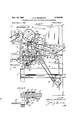
- FIGURE 2 is a fragmentary enlarged sectional view taken substantially on line 22 of FIGURE 1;
- FIGURE 3 is a sectional View taken substantially on line 33 of FIGURE 2;
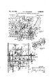
- FIGURE 4 is an enlarged side perspective view of one of the feeding mechanisms
- FIGURE 5 is a front perspective view of the mechanism of FIGURE 4.
- FIGURE 6 is a cross-sectional view of one of the feeding rollers
- FIGURE 7 is a fragmentary enlarged perspective end view of the collator.
- FIGURE 8 is an enlarged plan view of the drive and timing device for the feeding mechanism
- FIGURE 9 is a perspective view of the feeding rollers.
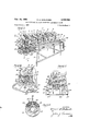
- a collator generally indicated 2 which comprises a main frame or support 3 which mounts any optional number of magazines 4 each of which is provided with a feeding mechanism 5,
- Each magazine or tray 4 is suitably mounted upon frame 3 and comprises a pair of upstanding sides 10, 11 and a bottom 12 which is inclined downwardly and terminates at the nip l3 formed between the upper metering roller assembly 14 and the fixed metering cylindrical retard 15 formed of rubber or other elastomer material.
- roller assembly 14 and retard 15 as best seen in FIGURE 2 are arranged substantially normal to the plane of the bottom 12 by locating the upper assembly 14 farther outwardly from the tray than the lower retard assembly 15.
- the metering roll assembly 14 has three cylindrical segments A, B and C of substantially equal diameter. Segment B is radically aligned with cylinder 15 and slightly spaced therefrom and segments A and C are laterally spaced from cylinder 15.
- the annular roller segmentsA, B and C are fastened to a support shaft 16 which is suitably journalled from the upstanding side panels 17, 17 which form the lateral sides of the respective dispensing stations.
- the lower retard assembly 15 is secured to shaft 19 Wmch also is suitably mounted by bracket 15.
- each roller segment A, B and C comprises a pair of complementary semi-cylindrical portions 20 and 21, portion 2t) being made of material having a low coefficient of friction such as polished steel or nylon.
- Portion 20 preferably has an integral hub portion 22 with a bore 23 admitting the associated shaft therethrough.
- the portion 21 is preferably elastomer, such as rubber, and a semi-cylindrical complement of portion 20 having an arcuate metallic backing 24 which fits against surface 25 of hub 22 and preferably bonded to the elastomer outer section 21 which is preferably rubber having a high coefiicient of friction.
- the portion 21 is secured by a bolt 27 to hub 22, bolt 27 also serving as a locking means to the associated shaft.
- bolt 27 also serving as a locking means to the associated shaft.
- Shaft 16 is provided with a sprocket 23 which is selectively driven by a chain 29 from a sprocket 3t) through a clutch 31 on a drive shaft 32 which extends the full length of the machine.
- the jaw clutch 31 comprises a pair of jaw members, member 33 being secured to shaft 32 and member 34 being slidable on the shaft and normally urged into engaged position by the spring 35.
- Member 34 is keyed to sprocket 28 which is journalled on shaft 2.
- the clutch is disengaged by the s lifter 35 which has one leg 37 engaging cam 33 on member 34- shifting it a? the feeder is governed by the lengths of the cam segments 46.
- the cam is driven by a shaft 48 which is journalled through the walls 17 and at one end has a sprocket 49 which is driven by a chain 50 which in turn is driven by a sprocket 51 from a countershaft 52 journalled in bearings 5'3 on frame portions 55.
- the shaft 52 is provided with a ratchet 57 which is driven by a pawl 58 on an eccentric 59 (FIG. 3) mounted on a shaft 60 which is journalled on the frame portion 55.
- the shaft 60 is driven by a sprocket 62 which is driven by a chain 63 trained about a sprocket 64 on a shaft 32 and sprocket as on a shaft 6'7.
- Shaft 67 is keyed to a gear 68 which meshes with gear 69 on a shaft 70.
- Shaft 70 is connected to a sprocket 71 which is driven by a chain 72 (FIGS. 2 and 8) which is trained about a sprocket 73 on an output shaft 74 of driven gear train in box 75 which is coupled to an electric motor '76.
- the shaft 70 runs the full length of the collating device and is journalled through the walls 1.7, of respective stations.
- Shaft 67 is connected to a feed wheel or roller '73, which is preferably of rubber or other elastomer material.
- the wheel 78 cooperates with similar wheel 81 keyed 0n the shaft 70. Wheels or puliout rolls 78, 81 are intercollated with deck slats 82, 32 which extend from the metering means 14, 15 to the transverse conveyor mechanism generally designated 8.
- the cards are issued from the metering means to the transfer mechanism along the deck 35 (FIG. 8) defined by laterally spaced slats 82.
- the transfer mechanism in addition to the deck 86 and receiving feed rollers 78, 81 comprises the discharge transfer rollers 87, 88 with Wheels 89, 90 which are carried on shafts 91 and 92, the latter being suitably journalled in the adjacent walls 17 and shaft 91 being mounted on brackets 83 saddled on shaft 92.
- Brackets 83 carry stays $54 which mount brackets 35 which support shaft 67.
- rollers 73, 81 deliver to rollers 87, 88 which are driven by a sprocket 94 on shaft 70 driving chain 95 (FIGS. 2 and 8) which drives sprocket 95 on shaft 92, roller 87 being driven by contact with roller 88.
- the timing drive for the transverse conveyor is taken from the shaft 48 which has a gear 97 driving a reversing gear 98 on shaft 99 carried from end structure 55.
- Shaft 99 (FIG. 7) has a sprocket 100 which drives a chain 181 (FIGS. 2 and 7) which drives a sprocket 1G2 011 a shaft 103 carried from bearing means 104 on support structure 55.
- Shaft 103 has a bevel gear 105 meshing with bevel gear 1% on a shaft 197, which drives through sprocket 108, chain res, sprocket 11d and shaft 111 rotatable on support 112, a timing cam wheel 113 with cam segments 114 which actuate a clutch 115 engaging the clutch elements thereof to establish drive from shaft 118, which through a bevel gearing 119, 126 is driven from shaft 6% to the sprocket 121 which drives chain 122 and sprocket 123 which drives shaft 124 carried between supports 112,.
- Shaft 124 drives a sprocket 127 which drives the conveyor chain 139 which is suitably supported at the delivery end 131 from an idler sprocket and shaft assembly 132 from which the cards are deposited onto the stacking table 9.
- the cards '7 issue from the respective stations onto the transition deck which comprises a pair of laterally spaced inboard and outboard shelf portions 135, 136 defining a vertical slot 137 between which pass the fingers 138 on chain 13%, the fingers sweeping the cards off the transition stations onto the transfer shelves 139, 140 which are spaced below shelves 135, 136 and extends the full length of the collator from its pick up end 14d to its delivery end 131.
- a novel collator having a simplified timed drive such that the metering is interrupted and the conveyor then is actuated to collect the cards from the respective stations and deposit them upon the table 9.
- a novel metering and transfer mechanism is disclosed which includes rollers having segments of different coefiicients of friction so related to one another such that as the delivering rolls discharge the cards the receiving rolls grasp the cards, the aggressive areas of the latter rolls pulling the cards from be tween the non-aggressive areas of the former rolls. The assured delivery thus prevents defeat of the timing cycle as set by the disposition of the cams 46 and 114 and in the event of slight mistiming, the slip in the metering rolls overrides the timing means.
- a feeding source comprising a plurality of feeding stations, each station comprising a chute and metering roller means at the bottom of the chute, said roller means comprising substantially semi-cylindrical sections of different substance providing areas of relatively high and relatively low coefficient of friction to accommodate slippage of articles passing therealong at the areas of low coefiicient of friction, pullout means disposed in intercepting relation to the metering roller means and spaced therefrom a distance less than the length of one of said articles, said pullout means operating in timed relation with and at a greater speed than said metering roller means and upon faulty feeding of articles from the metering roller means said pullout means drawing said faultily fed articles away from the metering roller means when the areas of low coetiicient of friction of said metering roller means are in slipping engagement with the article.
Description
Nov. 24, 1964 E. s. GODLEWSKI 3,158,366
COLLATING DEVICE WITH SELECTIVE DISPENSING MEANS Filed March 1, 1962 3 Sheets-Sheet 1 INVENTOR.
Nov. 24, 1964 E. s. GODLEWSKI 3,158,366
COLLATING DEVICE WITH SELECTIVE DISPENSING MEANS Filed March 1. 1962 3 Sheets-Sheet 2 3.2.
INVENTOR.
W BYPM. L/ L 119 d Nov. 24, 1964 E. s. GODLEWSKI 6 COLLATING DEVICE WITH SELECTIVE DISPENSING MEANS Filed March 1. 1962 I 3 Sheets-Sheet 3 94 81 ya /Mlc United States Patent 3,153,356 CGLLATING DEVICE WITH SELECTIVE DESPENSING MEAN Edward d. Gorllcwsfai, 2835 liartin Ave, Melrose Park, Ill. Filed Mm. I, 1962, Ser. No. 176,705 1 Claim. (Cl. 27ll58) This invention pertains to collators particularly adapted, though not necessarily restricted, to the sorting and packaging of greeting cards In the collators heretofore available, complicated driving trains and feeding devices are used to insure accurate dispensing of such cards from a plurality of magazines from which the cards are gathered and packaged. These mechanisms require constant critical adjustment and a skilled operator to use.
A general object of my invention is to provide a novel feeding mechanism and simplified drives therefor which wfll be readily adjustable and substantially trouble free.
The invention contemplates a feeding device comprising cooperating rollers which have areas of high and low coetlicient of friction such that they obtain a positive grasp upon a card presented thereto and which also readily release the card when required by the receiving mechanism.
More specifically the invention comprehends a novel feeding mechanism comprising receiving and discharging sets of rollers, each set comprising at least two opposed rollers and at least one set of rollers havin a segment of elastomer material and a segment of plastic material such as nylon or steel, these rollers being so driven that corresponding sections oppose each other so that they alternately present grasping and sliding surfaces, the sets of rollers also being spaced apart slightly less than the length of the article passing therebetween and the rollers being so timed that upon the article being grasped by the receiving of rollers, the other set of rollers engage the article with the sliding surfaces so as to obtain ready withdrawal of the cards from one set of rollers to the other.
A further object of the invention is to provide a novel simplified mechanism for gathering the dispersed articles and which is timed with the dispensers by a simple driving train.
These and other objects and advantages inherent in and encompassed by the invention will become more apparent from the specification and the drawings, wherein:
FIGURE 1 is a fragmentary perspective view of my novel eollator;
FIGURE 2 is a fragmentary enlarged sectional view taken substantially on line 22 of FIGURE 1;
FIGURE 3 is a sectional View taken substantially on line 33 of FIGURE 2;
FIGURE 4 is an enlarged side perspective view of one of the feeding mechanisms;
FIGURE 5 is a front perspective view of the mechanism of FIGURE 4;
FIGURE 6 is a cross-sectional view of one of the feeding rollers;
FIGURE 7 is a fragmentary enlarged perspective end view of the collator; and
FIGURE 8 is an enlarged plan view of the drive and timing device for the feeding mechanism;
FIGURE 9 is a perspective view of the feeding rollers.
Description 0]" the Invention Describing the invention in detail and having particular reference to the drawings, there is shown a collator generally indicated 2 which comprises a main frame or support 3 which mounts any optional number of magazines 4 each of which is provided with a feeding mechanism 5,
3,153,356 Patented Nov. 24, 1964 the magazines and associated feeding mechanisms defining dispensing stations 6 which discharge cards 7 onto a gathering means 8 which in timed sequence with the operation of the dispensing stations 6 advances laterally of the stations and discharges the desired assortment of cards in a bundle onto a station 9 at one end of the collator.
Each magazine or tray 4 is suitably mounted upon frame 3 and comprises a pair of upstanding sides 10, 11 and a bottom 12 which is inclined downwardly and terminates at the nip l3 formed between the upper metering roller assembly 14 and the fixed metering cylindrical retard 15 formed of rubber or other elastomer material.
The roller assembly 14 and retard 15 as best seen in FIGURE 2 are arranged substantially normal to the plane of the bottom 12 by locating the upper assembly 14 farther outwardly from the tray than the lower retard assembly 15.
The metering roll assembly 14 has three cylindrical segments A, B and C of substantially equal diameter. Segment B is radically aligned with cylinder 15 and slightly spaced therefrom and segments A and C are laterally spaced from cylinder 15. The annular roller segmentsA, B and C :are fastened to a support shaft 16 which is suitably journalled from the upstanding side panels 17, 17 which form the lateral sides of the respective dispensing stations.
The lower retard assembly 15 is secured to shaft 19 Wmch also is suitably mounted by bracket 15.
As best seen in FIGURE 6 which illustrates the construction of each roller segment A, B and C, all being of substantially identical construction and therefore like numerals will be applied to like parts, comprises a pair of complementary semi-cylindrical portions 20 and 21, portion 2t) being made of material having a low coefficient of friction such as polished steel or nylon. Portion 20 preferably has an integral hub portion 22 with a bore 23 admitting the associated shaft therethrough. The portion 21 is preferably elastomer, such as rubber, and a semi-cylindrical complement of portion 20 having an arcuate metallic backing 24 which fits against surface 25 of hub 22 and preferably bonded to the elastomer outer section 21 which is preferably rubber having a high coefiicient of friction. The portion 21 is secured by a bolt 27 to hub 22, bolt 27 also serving as a locking means to the associated shaft. On rollers A and C there are bonded strips of soft, sponge-like material 21a, as rubber, on the harder rubber material 21, the strips 21a serving as auxiliary grabs against the articles being dispensed. It will be seen that the segments of high friction are axially aligned and the low coefhcient of friction segments are also axially aligned.
The clutch is disengaged by the s lifter 35 which has one leg 37 engaging cam 33 on member 34- shifting it a? the feeder is governed by the lengths of the cam segments 46.
The cam is driven by a shaft 48 which is journalled through the walls 17 and at one end has a sprocket 49 which is driven by a chain 50 which in turn is driven by a sprocket 51 from a countershaft 52 journalled in bearings 5'3 on frame portions 55.
The shaft 52 is provided with a ratchet 57 which is driven by a pawl 58 on an eccentric 59 (FIG. 3) mounted on a shaft 60 which is journalled on the frame portion 55.
The shaft 60 is driven by a sprocket 62 which is driven by a chain 63 trained about a sprocket 64 on a shaft 32 and sprocket as on a shaft 6'7. Shaft 67 is keyed to a gear 68 which meshes with gear 69 on a shaft 70. Shaft 70 is connected to a sprocket 71 which is driven by a chain 72 (FIGS. 2 and 8) which is trained about a sprocket 73 on an output shaft 74 of driven gear train in box 75 which is coupled to an electric motor '76.
The shaft 70 runs the full length of the collating device and is journalled through the walls 1.7, of respective stations. Shaft 67 is connected to a feed wheel or roller '73, which is preferably of rubber or other elastomer material.
The wheel 78, cooperates with similar wheel 81 keyed 0n the shaft 70. Wheels or puliout rolls 78, 81 are intercollated with deck slats 82, 32 which extend from the metering means 14, 15 to the transverse conveyor mechanism generally designated 8.
The cards are issued from the metering means to the transfer mechanism along the deck 35 (FIG. 8) defined by laterally spaced slats 82. The transfer mechanism in addition to the deck 86 and receiving feed rollers 78, 81 comprises the discharge transfer rollers 87, 88 with Wheels 89, 90 which are carried on shafts 91 and 92, the latter being suitably journalled in the adjacent walls 17 and shaft 91 being mounted on brackets 83 saddled on shaft 92. Brackets 83 carry stays $54 which mount brackets 35 which support shaft 67. It will be understood that the spacing from the metering rolls to the receiving transfer rolls is slightly less than the corresponding dimensions of cards to be passed therebetween and that by the metering means having alternating areas of high and low friction, the cards are securely grasped in the intake nip 93 of the transfer rollers 78, 81 by the continuous high frictional areas thereof and are pulled from the low frictional areas 20 of the metering roller 14. Thus a positive feeding of the material from the metering roller assembly to the transfer is assured. Rollers 73, 81 deliver to rollers 87, 88 which are driven by a sprocket 94 on shaft 70 driving chain 95 (FIGS. 2 and 8) which drives sprocket 95 on shaft 92, roller 87 being driven by contact with roller 88.
The timing drive for the transverse conveyor is taken from the shaft 48 which has a gear 97 driving a reversing gear 98 on shaft 99 carried from end structure 55.
Shaft 99 (FIG. 7) has a sprocket 100 which drives a chain 181 (FIGS. 2 and 7) which drives a sprocket 1G2 011 a shaft 103 carried from bearing means 104 on support structure 55.
125 of the frame.
it will be observed that the cards '7 issue from the respective stations onto the transition deck which comprises a pair of laterally spaced inboard and outboard shelf portions 135, 136 defining a vertical slot 137 between which pass the fingers 138 on chain 13%, the fingers sweeping the cards off the transition stations onto the transfer shelves 139, 140 which are spaced below shelves 135, 136 and extends the full length of the collator from its pick up end 14d to its delivery end 131.
The foregoing description discloses a novel collator having a simplified timed drive such that the metering is interrupted and the conveyor then is actuated to collect the cards from the respective stations and deposit them upon the table 9. A novel metering and transfer mechanism is disclosed which includes rollers having segments of different coefiicients of friction so related to one another such that as the delivering rolls discharge the cards the receiving rolls grasp the cards, the aggressive areas of the latter rolls pulling the cards from be tween the non-aggressive areas of the former rolls. The assured delivery thus prevents defeat of the timing cycle as set by the disposition of the cams 46 and 114 and in the event of slight mistiming, the slip in the metering rolls overrides the timing means.
It will be understood that the foregoing disclosure sets forth a preferred embodiment of the invention and that various other forms will become readily apparent to those skilled in the art within the scope of the appended claim.
What is claimed is:
in a collator, the combination of a feeding source comprising a plurality of feeding stations, each station comprising a chute and metering roller means at the bottom of the chute, said roller means comprising substantially semi-cylindrical sections of different substance providing areas of relatively high and relatively low coefficient of friction to accommodate slippage of articles passing therealong at the areas of low coefiicient of friction, pullout means disposed in intercepting relation to the metering roller means and spaced therefrom a distance less than the length of one of said articles, said pullout means operating in timed relation with and at a greater speed than said metering roller means and upon faulty feeding of articles from the metering roller means said pullout means drawing said faultily fed articles away from the metering roller means when the areas of low coetiicient of friction of said metering roller means are in slipping engagement with the article.
References (Iited by the Examiner UNITED STATES PATENTS 1,978,056 10/34 Nelson 271-36 1,980,725 11/ 34 Hartley 27l36 1,991,989 2/35 Trompier 271-36 2,224,137 12/40 Breman et al. 27137 2,308,061 1/43 Dodge et a1 27052 2,343,187 2/44 Jagger 271-36 2,705,636 4/55 Labombarde 27136 2,966,354 12/60 Gore 27055 2,979,330 4/61 Weber 27136 3,032,338 5/62 Anderson et al 27136 3,054,612 9/62 Godlewski 27058 EUGENE R. cAsozto, Primary Examiner;
ROBERT A. LEZGHEY, ROBERT E. PULFREY, Ex-
aminers.
Priority Applications (1)
| Application Number | Priority Date | Filing Date | Title |
|---|---|---|---|
| US176705A US3158366A (en) | 1962-03-01 | 1962-03-01 | Collating device with selective dispensing means |
Applications Claiming Priority (1)
| Application Number | Priority Date | Filing Date | Title |
|---|---|---|---|
| US176705A US3158366A (en) | 1962-03-01 | 1962-03-01 | Collating device with selective dispensing means |
Publications (1)
| Publication Number | Publication Date |
|---|---|
| US3158366A true US3158366A (en) | 1964-11-24 |
Family
ID=22645500
Family Applications (1)
| Application Number | Title | Priority Date | Filing Date |
|---|---|---|---|
| US176705A Expired - Lifetime US3158366A (en) | 1962-03-01 | 1962-03-01 | Collating device with selective dispensing means |
Country Status (1)
| Country | Link |
|---|---|
| US (1) | US3158366A (en) |
Cited By (8)
| Publication number | Priority date | Publication date | Assignee | Title |
|---|---|---|---|---|
| US3356361A (en) * | 1965-06-04 | 1967-12-05 | Pitney Bowes Inc | Sheet packaging machine |
| US3438622A (en) * | 1965-09-13 | 1969-04-15 | Wilhelm Zilling | Sheet feeding apparatus for binding machines |
| US3931640A (en) * | 1973-04-04 | 1976-01-06 | Sanyo Electric Company, Ltd. | Automatic flexible record feeding device |
| US4030413A (en) * | 1975-04-30 | 1977-06-21 | Young Robert D | Mechanisms for feeding documents from a stack thereof |
| US4473221A (en) * | 1980-09-30 | 1984-09-25 | Konishiroku Photo Industry Co., Ltd. | Paper feeding roller |
| US5141216A (en) * | 1989-11-02 | 1992-08-25 | Sitma S.P.A. | Apparatus for the controlled feed of products in sheet form in a collating or packaging machine |
| US5857669A (en) * | 1996-10-10 | 1999-01-12 | Bell & Howell Cope Company | Method and apparatus for high speed merging of sheet material onto a transport from the side |
| US6648586B1 (en) | 1999-03-30 | 2003-11-18 | Premark Rwp Holdings Inc. | Sample chip collating apparatus |
Citations (11)
| Publication number | Priority date | Publication date | Assignee | Title |
|---|---|---|---|---|
| US1978056A (en) * | 1931-04-28 | 1934-10-23 | Standard Envelope Mfg Company | Feeding device for envelope folding machines or the like |
| US1980725A (en) * | 1930-12-22 | 1934-11-13 | Addressograph Co | Printing machine |
| US1991989A (en) * | 1935-02-19 | Sheet separating device | ||
| US2224137A (en) * | 1938-05-02 | 1940-12-10 | Davidson Mfg Company | Friction feeder |
| US2308061A (en) * | 1940-05-31 | 1943-01-12 | Libbey Owens Ford Glass Co | Plastic cutting apparatus |
| US2343187A (en) * | 1942-05-23 | 1944-02-29 | Ditto Inc | Feeding sheets to duplicating machines |
| US2705636A (en) * | 1951-04-27 | 1955-04-05 | Bombard Leon E La | Feed mechanism in paper box machines |
| US2966354A (en) * | 1958-08-07 | 1960-12-27 | Miehle Goss Dexter Inc | Signature handling apparatus |
| US2979330A (en) * | 1957-04-15 | 1961-04-11 | Weber Carl | Sheet separating device |
| US3032338A (en) * | 1958-06-19 | 1962-05-01 | Anderson Alfred | Sheet feeders |
| US3054612A (en) * | 1960-01-18 | 1962-09-18 | Edward S Godlewski | Collating device |
-
1962
- 1962-03-01 US US176705A patent/US3158366A/en not_active Expired - Lifetime
Patent Citations (11)
| Publication number | Priority date | Publication date | Assignee | Title |
|---|---|---|---|---|
| US1991989A (en) * | 1935-02-19 | Sheet separating device | ||
| US1980725A (en) * | 1930-12-22 | 1934-11-13 | Addressograph Co | Printing machine |
| US1978056A (en) * | 1931-04-28 | 1934-10-23 | Standard Envelope Mfg Company | Feeding device for envelope folding machines or the like |
| US2224137A (en) * | 1938-05-02 | 1940-12-10 | Davidson Mfg Company | Friction feeder |
| US2308061A (en) * | 1940-05-31 | 1943-01-12 | Libbey Owens Ford Glass Co | Plastic cutting apparatus |
| US2343187A (en) * | 1942-05-23 | 1944-02-29 | Ditto Inc | Feeding sheets to duplicating machines |
| US2705636A (en) * | 1951-04-27 | 1955-04-05 | Bombard Leon E La | Feed mechanism in paper box machines |
| US2979330A (en) * | 1957-04-15 | 1961-04-11 | Weber Carl | Sheet separating device |
| US3032338A (en) * | 1958-06-19 | 1962-05-01 | Anderson Alfred | Sheet feeders |
| US2966354A (en) * | 1958-08-07 | 1960-12-27 | Miehle Goss Dexter Inc | Signature handling apparatus |
| US3054612A (en) * | 1960-01-18 | 1962-09-18 | Edward S Godlewski | Collating device |
Cited By (8)
| Publication number | Priority date | Publication date | Assignee | Title |
|---|---|---|---|---|
| US3356361A (en) * | 1965-06-04 | 1967-12-05 | Pitney Bowes Inc | Sheet packaging machine |
| US3438622A (en) * | 1965-09-13 | 1969-04-15 | Wilhelm Zilling | Sheet feeding apparatus for binding machines |
| US3931640A (en) * | 1973-04-04 | 1976-01-06 | Sanyo Electric Company, Ltd. | Automatic flexible record feeding device |
| US4030413A (en) * | 1975-04-30 | 1977-06-21 | Young Robert D | Mechanisms for feeding documents from a stack thereof |
| US4473221A (en) * | 1980-09-30 | 1984-09-25 | Konishiroku Photo Industry Co., Ltd. | Paper feeding roller |
| US5141216A (en) * | 1989-11-02 | 1992-08-25 | Sitma S.P.A. | Apparatus for the controlled feed of products in sheet form in a collating or packaging machine |
| US5857669A (en) * | 1996-10-10 | 1999-01-12 | Bell & Howell Cope Company | Method and apparatus for high speed merging of sheet material onto a transport from the side |
| US6648586B1 (en) | 1999-03-30 | 2003-11-18 | Premark Rwp Holdings Inc. | Sample chip collating apparatus |
Similar Documents
| Publication | Publication Date | Title |
|---|---|---|
| US4715593A (en) | Stack-supporting bottom feed conveyor | |
| US3158366A (en) | Collating device with selective dispensing means | |
| US3979112A (en) | Sheet stacking and interleaving apparatus | |
| US3540970A (en) | Tipping machine | |
| US3368660A (en) | Article grouper and feeder | |
| US4522382A (en) | Sheet and envelope feed apparatus for a printer and associated methods | |
| US3459420A (en) | Sheet unstacking and fanning machine | |
| US2158727A (en) | Process for separating handysets and piles and apparatus therefor | |
| US3054612A (en) | Collating device | |
| EP0538765A1 (en) | Method and device for forming groups of flat products, in particular biscuits, for supply to a packing line | |
| US3805478A (en) | Tray loading apparatus | |
| US3608891A (en) | Mechanism for successively delivering sheet articles from a stack thereof to a folding machine | |
| US2936060A (en) | Article combiner | |
| CN1217982A (en) | Paper aligning apparatus and method thereof | |
| DE2151424A1 (en) | Packaging device | |
| US4549729A (en) | Overlap conveyor apparatus | |
| US3794232A (en) | Collator and web feed control means for the same | |
| US3052466A (en) | Collating machine | |
| US4477066A (en) | Apparatus for separating overlapped sheets of folded products | |
| US4550902A (en) | Stock feeding machine | |
| US3202421A (en) | Machine for packaging articles | |
| US5004219A (en) | Up-feed conveyor system | |
| US2094938A (en) | Delivery device for rotary printing machines | |
| US5924687A (en) | Newspaper hopper and feeder having rail-mounted, one-way rollers | |
| US3218060A (en) | Sheet feeding apparatus |