US3136985A - Electric alarm device for sensing signal over power distribution system - Google Patents
Electric alarm device for sensing signal over power distribution system Download PDFInfo
- Publication number
- US3136985A US3136985A US217628A US21762862A US3136985A US 3136985 A US3136985 A US 3136985A US 217628 A US217628 A US 217628A US 21762862 A US21762862 A US 21762862A US 3136985 A US3136985 A US 3136985A
- Authority
- US
- United States
- Prior art keywords
- alarm
- relay
- cam
- clutch
- signal
- Prior art date
- Legal status (The legal status is an assumption and is not a legal conclusion. Google has not performed a legal analysis and makes no representation as to the accuracy of the status listed.)
- Expired - Lifetime
Links
Images

Classifications
-
- G—PHYSICS
- G04—HOROLOGY
- G04C—ELECTROMECHANICAL CLOCKS OR WATCHES
- G04C21/00—Producing acoustic time signals by electrical means
-
- G—PHYSICS
- G04—HOROLOGY
- G04B—MECHANICALLY-DRIVEN CLOCKS OR WATCHES; MECHANICAL PARTS OF CLOCKS OR WATCHES IN GENERAL; TIME PIECES USING THE POSITION OF THE SUN, MOON OR STARS
- G04B47/00—Time-pieces combined with other articles which do not interfere with the running or the time-keeping of the time-piece
-
- G—PHYSICS
- G08—SIGNALLING
- G08B—SIGNALLING OR CALLING SYSTEMS; ORDER TELEGRAPHS; ALARM SYSTEMS
- G08B27/00—Alarm systems in which the alarm condition is signalled from a central station to a plurality of substations
Definitions
- the present invention relates to electric alarm devices and more particularly to a device for sounding an alarm in response to an alarm signal superimposed upon the regular A.-C. line at a power station or distribution point.
- resonant relays particularly of the self-holding type, have beenfound to be of poor reliability and susceptible to response to transients, harmonics and other interference of various kinds which may exist on a supply line, particularly when certain types of consuming equipment is connected to the line.
- Spurious operation is, of course. highly undesirable where such units are employed for a defense alert because of the possibility of producingpanic and confusion.
- an object of the present invention to provide an electric alarm device which responds to a sustained signal superimposed upon the regular A.-C. supply line and which has a degree of reliability which exceeds that of conventional or available devices yet which may be manufactured and sold at such low cost as to enable usage on a universal basis. More specifically, it is an object of the present invention to provide an electric alarm device which tests for, or samples, the signal at spaced time intervals in order to insure that the signal is sustained and hence intentional before sounding the alarm. It is, moreover, an object to provide an electric alarm device which automatically resets itself to the desired initial condition in the event that no signal persists on the line during oneof a series of sampling intervals.
- an object of the present invert tion to provide an alarm device which is inherently sensitive and which will operate reliably upon receipt of a sustained signal even though such signal, because of attenuation in the line, may drop to a fraction of the standard minimum level.
- an alarm device which forms an integral part of a clock driving mechanism so that indication, by the hands of the clock, of the correct time constitutes proof positive that the device is operative and that the device has remained operas tive since first being put into use, thus rulingout the possibility of intermittent operation.
- an A.-C. motor driving mechanism which is coupled to a switching mechanism through a clutch and in which novel means are included forinsuring that the clutch faces engage and disengagewith positive action.
- a clutching arrangement for an alarm device having biasing means for effecting axial and rotational movement of a switching cam and in which'the effects of the two biasing means are cumulative for the positive overcoming of any friction and for positive reset to a starting position follow-, ing response to a short spurious signal at the response frequency. 7 t
- an object of the device to provide an alarm device for the purposes set forth and which maybe inexpensively manufactured using readily available or easily made components, preferably integrated with a clock mechanism, but which may be made and sold for only a small amount more thana conventional clock.
- FIGURE 1 is a perspective of an alarm device constructed in accordance with the present invention having an integral clock for signalling a continued state of readiness.
- FIG. 2 is a diagram of the alarm device of FIG. 1 and including theassociated circuitry.
- FIG. 3 is a side elevation of the cam disc employed'in the device of FIG. 2.
- p v p FIGS. 3a and 3b are fragmentary top and bottom views respectively of the cam disc of FIG. 3.
- FIGS. 4-4d are a set of stop motion views showing successive steps in the operation of the device.
- FIGS. 5 and 5a are fragmentary top and side views, respectively, of the cam disc and associated follower prior to being reset to initial position.
- FIG. 6 is a fragmentary side view of the cam disc showing the beginning of the restoring movement.
- FIG. 7 is similar to FIG. 6 but showing the relation of the parts at the end of the restoring movement.
- FIG. 8 shows a resonant reed relay of the self-holding type which may be employed in the circuit of FIG. 2.
- FIG. 1 shows an alarm device 10 constructed in accordance with the present arranged opposite suitable aperture .17 formed in the housing of the device.
- FIG. 2 is a combined pictorial and wiring diagram
- the incoming A.-C. leads are 1ndicated at 21, 22 respectively supplying left and right hand buses.
- a resonant relay 25 is provided having a coil 26 cooperating with a resonant reed 27.
- the reed carries an electrical contact 28 which cooperates with a stationary contact 29.
- periodic closure of the reed relay contacts 28, 29 is utilized to energize a D.-C. relay 30 having a coil 31, an armature 32 and contacts 33, 34 respectively. Since the relay 30 is responsive to direct current, a rectifier 35 is connected in series with the supply circuit and the current is filtered by a storage capacitor 36 connected in parallel with the relay winding.
- the relay 25 is made electrically as well as mechanically responsive to the high frequency alarm signal by connecting a capacitor 37 in series with the coil 26.
- the reed 27 of the relay 25 begins to vibrate with rapid buildup of the amplitude to a point where momentary contact is made between terminals 28, 29.
- This causes the pulses of current to flow through the rectifier 35 causing pulses of D.-C. to be applied to the input of the D.-C. relay.
- the peaks and valleys of the incoming current are leveled out so that the relay is closed as long as the incoming signal persists.
- a constantly running A.-C. drive motor is connected across the incoming lines 21, 22 and a cyclically operating switch mechanism is coupled to the'motor, upon receipt of an alarm signal, by an electromagnet clutch.
- an AC. drive motor 40 which will be recognized as being of a conventional type employed in the driving of clocks and timing mechanisms having input terminals 41, 42 and an output pinion 43.
- a switch mechanism is provided in the form of a cyclical cam disc having a.
- cam follower 51 in the form of a spring finger, riding on the edge thereof.
- the cam disc 50 is mounted for rota tion on a pin 52 which may be secured in a suitable way to the frame of the device.
- a clutch plate is provided having a circular rack or gear 61 which is in mesh with the output pinion 43 of the motor.
- the upper face 62 of the member 60 is radially fluted cooperating with a similarly fluted face 63 formed on the underside of the cam disc 50.
- the cam disc 50 is mounted for limited endwise movement under the control of a clutch relay 70.
- the latter has a coil 71 and an armature 72 which is pivoted for rocking movement on a pivot pin 73.
- the armature 72 is coupled to the cam disc by providing a forked extension 74 which cooperates with a collar 75 on the disc.
- a shading ring 76 which surrounds a portion of the relay core, provides suflicient offset flux so that the armature is positively attracted when the relay coil is energized with alternating current.
- the armature is biased away from the relay core by a return spring 77.
- means are provided for responding to the initial receipt of a signal at the alarm frequency and for thereafter sampling the signal at spaced time intervals, in order to insure that it is a sustained, and therefore intentional, signal, with provision for restoring the mechanism to its initial state in the event that the incoming signal is not detected during any one of the sampling intervals.
- means including a resonant relay are employed for causing initial clutch engagement and for thereafter momentarily dropping out the resonant relay to define a succession of sampling intervals but with the clutch surfaces being maintained in engagement during the period of drop-out.
- the cam disc 50 is formed, following a shoulder 80 defining the start position, with peripheral lobes 31, 82 having adjacent valleys 83-85 operating a normally closed contact in series with the resonant reed relay so that the circuit of the later is periodically opened to produce relay drop-out.
- a common or supply contact 87 which, as shown, is directly connected to the incoming line 22.
- the relay 36 is closed operating the clutch relay 7%) so that the cam disc 50 is forced downwardly and begins to move, the motor 40 being constantly energized.
- the action is such as to open circuit the contact 86 which serves to drop out the resonant relay 25 for a short time interval.
- means are provided for maintaining the clutch faces in engagement during the period of dropout of the resonant reed relay. In the present instance this is accomplished by providing a normally open contact 93 which is operated by the cam follower 51 and which is closed to complete an auxiliary holding circuit to the clutch relay 79 prior to the time that the normally closed contact 86 opens The lead which forms the holding circuit as indicated at 95.
- Means are provided for energizing the alarm device 16 during the terminal portion of the cam movement and after the sampling lobes have been successfully traversed. This is accomplished by providing a high plateau 100 on the cam disc and by providing a third contact 101 which is operated by the cam follower only when the cam follower is raised to the level of the plateau.
- the alarm device 16' is in the form of an A.-C. electromagnet 105 havinga winding 106 and a pole structure 107 which serves to vibrate a buzzer blade 108 which in turn in connected to a diaphraim 109. The sound level produced by this device is sufficiently high as to be heard throughout the home or other establishment where the present system is used.
- the restoring means includes a restoring arm 110 which is pivoted for rotation about a pin 111 and which has a tip 112 which cooperates with a radial abutment 113 on the cam disc and which has a cooperating flange 114 on the shaft 52.
- Restoring bias is provided by a return spring 115.
- This spring is so constructed that it not only applies a rotational returning force to the arm 110 but also an axial or upward returning force which tends to move the flange 114, and the cam disc 50 which is connected to it, in the axial or upward direction.
- connection between the arm 110 and pin 111 is purposely made loose and the spring 115 is cockedat an angle so as to exert a force which has an upward as well as rotational components.
- the arm may be rigidly secured to the pin 111 in which case the arm may be made of resilient sheet metal to exert a biasing force upwardly against the flange 114.
- the armature spring may be relied upon to provide the upward bias.
- FIGS. 5 and 5a show the condition of obstruction between the lobe 81 and the cam follower 51.
- FIG. 4 shows the initial condition of the disc.
- an alarm signal is received causing closure of the relays 25, 30 and actuation of the clutch relay 70, the clutch faces are engaged and the disc 50 begins to rotate.
- the cam follower 51 strikes the lobe 81, contact 93 is closed thereby establishing an auxiliary circuit from supply line 22 via a lead 95 to the clutch relay.
- FIG. 4 shows the initial condition of the disc.
- the normally closed contact 86 is opened, thereby open circuiting the lead 92 which is in series with the winding of the resonant relay.
- the relay thereupon drops out but, as stated, this does not affect the continued rotation of the motor during the period of drop-out.
- the normal supply circuit via the line 92 to the resonant relay is reestablished. If the alarm signal is present on the line, the resonant relay 25 recloses, clos-, ing the D.-C. relay 30 providing energization for the clutch relay 70 so that the clutch remains engaged.
- the clutch relay is thusno longer dependent upon the auxa iliary holding contact 93, which opens.
- the operation set forth in FIGS. 4a-4c is repeated with respect to the succeeding lobe 82.
- the cam disc rotating at one r.p.m., sampling occurs at the endof two five second intervals.
- the cam follower at the end of twelve seconds rides up on the plateau 100 thereby energizing the contacts 101 to sound the alarm device 16.
- contacts 93, 87 are made so that the holding circuit 95 leading to the clutch relay continues to be energized thereby insuring that the motor remains clutched in until the disc cam has completed a full revolution.
- the relay indicated at 125, has a coil 126 and a vibratory reed armature 127 with contacts 128, 129.
- the magnetic structure includes an auxiliary magnetic leg 130 having an unshaded pole tip 131and a shaded pole tip 132 encircled by a shading loop 133.
- the poles 131, 132 are sufiiciently spaced from the reed 127 so that they are not capable of attracting it when operating alone.
- the reed upon receipt of a high frequencysignal for which the reed 127 is tuned, the reed vibrates through an amplitude to bring it into the neighborhood of the poles 131, 132.
- the poles excited by 60 cycle current, thereupon attract the reed 127,,holding it captive and with solid contact made at the contacts 128, 129.
- the relay of the self-holding type as shown in FIG. 8, the
- the device is always in readiness to respond to an incoming alarm signal.
- means are provided for indicating that the motor continues to operate and that it has, indeed, operated without interruption since the device was put into service. This is accomplished by the clock hands 11-13.
- the visible movement of the sweep second hand 13 is proof that the motor is rotating and the fact that the time is accurately indicated by the hour and minute hands shows that no interruption has occurred thereby precluding malfunction due to an intermittently operating motor. I11 the drawing the clock driving train has been indicated diagrammatically at 135 for the sake of simplicity and since gear drive trains are Well understood by those skilled in the art.
- the relays may be designed and adjusted for response to signals which are at a level lower than the standard minimum of about one volt, thereby insuring the sounding of an alarm where the alarm device is used under conditions where the incoming signal is attenuated as, for example, where a large amount of shunting capacitance to ground may exist.
- the device serves the added function of a clock, it may be employed unobtrusively wherever desired.
- the component parts are inherently inexpensive so that the complete unit may be made for only a small amount more than the cost of a clock of conventional type.
- alarm means shall be deemed to include in addition to an actual sounding device any other type of alarm or, indeed, contacts which are operated to actuate an external or remote alarm.
- resonant relay will be understood to apply to electrically resonant as well as mechanically resonant relays.
- cam switch is intended in a generic sense to denote any switch driven by a rotating shaft.
- clock hands is intended to denote any means for feasible indication of correct time.
- an electric alarm device for sounding an alarm in response to a signal at an alarm frequency superimposed on the regular A.-C. supply line
- the combination comprising a constantly driven A.-C. motor, a cam switch, a clutch interposed between the motor and the cam switch, a resonant relay having an input circuit coupled to the supply line for response to the alarm signal and having output contacts, said cam switch including normally closed contacts so arranged that when the cam is driven from a start position to a sampling position the resonant relay input circuit is momentarily opened to drop out the resonant relay, said cam switch further having normally open contacts for setting up an auxiliary circuit to the clutch to maintain the clutch energized during the period of drop-out, biasing means for disengaging the clutch and for restoring the cam to its start position upon failure of the resonant relay to reclose after its momentary opening due to absence of the alarm signal from the supply line, and alarm means actuated by the cam switch upon traversal of the sampling position and until the cam is driven back to its starting position.
- an alarm device for sounding an alarm in response to a signal at an alarm frequency superimposed on the A.-C. supply line
- the combination comprising an A.-C. motor permanently connected to the A.-C. supply line, a cycling cam switch, a clutch interposed between the motor and the cam switch, a resonant relay having an input circuit coupled to the supply line for response to the alarm signal and having output contacts coupled to the clutch, said cam switch being formed to define a plurality of sampling positions spaced over the first portion of the cam cycle, said cam switch including normally closed contacts in series with the resonant relay input circuit and so arranged that when the cam is driven to a sampling position the resonant relay input circuit is momentarily opened to drop out the resonant relay, said cam switch further having normally open contacts for setting up an auxiliary hold circuit to the clutch to maintain the clutch energized during the period of drop-out, biasing means for deenergizing the clutch and for restoring the cam to its start position upon failure of the resonant relay to reclose after
- an alarm device for sounding an alarm in response to a signal at an alarm frequency superimposed upon the reguiar A.-C. supply line
- the combination comprising an A.-C. motor arranged for permanent connection to the A.-C. supply line, a cycling cam switch, a clutch interposed between the motor and the cam switch, a resonant relay having m1 input circuit responsive to a signal at alarm frequency and having output contacts coupled to the clutch for energizing the same, said cam switch being formed to define a plurality of sampling positions, said cam switch having a first set of contacts interposed between the resonant relay and the supply line and so arranged that when the cam is driven to a sampling position the resonant relay input circuit is momentarily opened to drop out the resonant relay, auxiliary means for maintaining the clutch energized during periods of momentary drop-out of the resonant relay but for deenergizing the clutch upon failure of the resonant relay to reclose at any one of the sampling positions, and alarm means actu
- driving means including an A.C. motor arranged for permanent connection to the supply line for driving said hands, a cam switch, an electrically energized clutch for coupling the cam switch to the motor, a resonant relay having an input circuit normally connected to the supply line for response to a signal at alarm frequency and having output contact connected to the clutch for energizing the same when the relay closes for movement of the cam switch from a start position, said cam switch defining a reference position and a plurality of sampling positions and having contact means thereon interposed between the resonant relay and the supply line for momentary dropping out the resonant relay at each of said sampling positions, means for restoring the cam switch to its reference position upon failure of the resonant relay to reclose after momentary drop-out due to absence of the alarm signal from the supply line, and alarm means
- anelectrical alarm device for sounding an alarm in response to a signal at an alarm frequency superimposed on the regular A.-C. supply line
- the combination comprising an A.-C. driving motor arranged for constant connection to the A.-C. supply line, a cycling type switch mechanism, an electrically energized clutch for coupling the switch mechanism to the motor, a resonant relay having an input circuit normally coupled to the supply line for response to a signal at alarm frequency and having output contacts for energizing the clutch so that the switch mechanism is driven from a start position, said switch mechanism including contacts interposed between the relay circuit and the supply line and so arranged that the resonant relay is periodically dropped out for resampling of the alarm signal, means for restoring the switch mechanism to its start position upon failure of the resonant relay to reclose after dropout due to the then absence of the alarm signal from the A.-C.
- an electric alarm device for sounding an alarm in response to a signal at an alarm frequency superimposed upon the regular A.-C. supply line
- the combination comprising an A.-C. drive motor having provision for constant energization from the A.-C. line, a cam disc defining an alarm cycle and having a plurality of sampling lobes spaced over its initial portion followed by a plateau at a dilferent elevation than the lobes and having a cam follower riding thereon, a clutch for coupling the cam disc to the motor, a resonant relay having an input circuit normally coupled to the supply line for response to a signal at alarm frequency and having output contacts for energizing the clutch for rotation of the disc from a start position, said cam follower having a first set of contacts interposed between the supply line and the input circuit of the resonant relay for momentarily disconnecting the relay for sampling of the signal as the lobes traverse the cam follower, said cam follower having a second set of contacts for maintaining the clutch energize
- the combination comprising an A.-C. motor having provision for constant energization from the A.-C. supply line and having a clutch face, a cam disc having a clutch face arranged opposite the clutch face on the motor, a magnetic clutch actuator for moving the cam disc endwise between clutched and unclutched positions, a resonant relay having an input circuit normally coupled to the supply line for response to a signal at alarm frequency and having output contacts coupled to the magnetic clutch actuator, biasing means for biasing the cam disc endwise to its unclutched position and for biasing the cam disc rotationally to a start position, said cam disc having a toothed portion on the periphery thereof defining sampling positions, a cam follower riding on said teeth and having contacts interposed between the resonant relay and the line for momentarily dropping out the resonant relay for resampling the existence of the alarm signal so that upon
- an electric alarm device for sounding an alarm in response to a signal at an alarm frequency superimposed upon the regular A.-C. supply line
- the combination comprising an A.-C. motor having provision for constant energization from the A.-C. supply line and having a clutch face, a cam disc having a clutch face arranged opposite the clutch face on the motor, a magnetic clutch actuator for moving the cam disc endwise between clutched and unclutched positions, a resonant relay having an input circuit normally coupled to the supply line for response to a signal at alarm frequency and having output contacts coupled to the magnetic clutch actuator, biasing means for biasing the cam disc endwise to its unclutched position and for biasing the cam disc rota ionally to a start position, said cam disc having teeth on the periphery thereof defining sampling positions, a cam follower riding on said teeth and having contacts interposed between the resonant relay and the line for momentarily dropping out of the resonant relay for resampling the existence of the alarm signal so that upon
- an alarm device for sounding an alarm in response to a signal at an alarm frequency superimposed upon the regular A.-C. supply line
- the combination comprising a constantly driven ArC. motor, a motor driven switch, a clutch interposed between the motor and the switch, a resonant relay having an input circuit coupled to the supply line for response to the alarmsignal and having output contacts for engaging the clutch, an alarm device actuated upon continued driving of the switch over a predetermined time interval, means for dropping out the resonant relay periodically following initial engagement of the clutch for repeated sampling of the alarm signal and to confirm that the signal is intentionally initiated and persistent, and time indicating means coupled to the motor for providing constant visual indication that the motor is operating and that the motor has continued to operate from the time the device was put into use.
Description
June 9. 1 R. c. ROBINSON ETAL 3,136,985
ELECTRIC ALARM DEVICE FOR SENSING SIGNAL OVER POWER DISTRIBUTION SYSTEM Filed Aug. 17, 1962 2 Sheets-Sheet 1 INVENTORS. P41? 6. Pam/5m Ali/V i. PAT/Wm QW/fi Mafi /f TTY,
June 9. 1964 R. c. ROBINSON ETAL 3,136,985
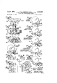
ELECTRIC ALARM DEVICE FOR SENSING SIGNAL OVER POWER DISTRIBUTION SYSTEM Filed Aug. 17, 1962 2 Sheets-Sheet 2 F 4 INITIAL POSITION MOTOR HOLD CIRCUIT CLOSED MOTOR HOLD CIRCUIT OPENED RESONANT RELAY CIRCUIT RECLOSED 50 I i l. 539%. F .8 F A 80 I 50 To CLUTCH 'PLA 42 RELAY co. m
TO NC. CONTACT 86 I United States Patent 3,136,985 ELECTRIC ALARM DEVICE FOR SENSING SIGNAL OVER POWER DISTRIBUTION SYSTEM Ralph C. Robinson, Alan E. Patrick, and David Morrison, Athens, Ga., assignors to General Time Corporation, New York, N.Y., a corporation of Delaware Filed Aug. 17, 1962, Ser. No. 217,628
. '9 Claims. (Cl. 34t)310) The present invention relates to electric alarm devices and more particularly to a device for sounding an alarm in response to an alarm signal superimposed upon the regular A.-C. line at a power station or distribution point.
In the development of a universal alarm system to be used for civil defense purposes or the like, it has been proposed to superimpose an alarm signal on the regular A.-C. line at a frequency which is higher and non-integrally related to the usual 60 cycle line frequency, for example, 255 cycles per second and having a voltage at least on the order of a volt or so at the point of detection. For the purpose of responding to the alarm signal it has been proposed to employ resonant reed relays attuned to the desired frequency and having means for holding in once the relay has been initially energized. In practice, resonant relays, particularly of the self-holding type, have beenfound to be of poor reliability and susceptible to response to transients, harmonics and other interference of various kinds which may exist on a supply line, particularly when certain types of consuming equipment is connected to the line. Spurious operation is, of course. highly undesirable where such units are employed for a defense alert because of the possibility of producingpanic and confusion.
There is also the risk that such devices may fail to operate in response to a strong and reliable. signal after long periods of inaction due to stickiness in the relays or motor shafts, or deterioration of sensitive electrical components, particularly where the environment is unfavorable due to moisture, heat, chemical vapors or the like. Devices which have been so constructed as to overcome the above difficulties have been too costly for general usage.
Accordingly, it is an object of the present invention to provide an electric alarm device which responds to a sustained signal superimposed upon the regular A.-C. supply line and which has a degree of reliability which exceeds that of conventional or available devices yet which may be manufactured and sold at such low cost as to enable usage on a universal basis. More specifically, it is an object of the present invention to provide an electric alarm device which tests for, or samples, the signal at spaced time intervals in order to insure that the signal is sustained and hence intentional before sounding the alarm. It is, moreover, an object to provide an electric alarm device which automatically resets itself to the desired initial condition in the event that no signal persists on the line during oneof a series of sampling intervals. It is a more detailed object to provide an electric alarm device which makes use of a resonant reed relay of the hold-in type, or which has external provision for effecting hold-in, without, however, being subject to the disadvantages usu-. ally associated with this type of relay.
It is, on the other hand, an object of the present invert tion to provide an alarm device which is inherently sensitive and which will operate reliably upon receipt of a sustained signal even though such signal, because of attenuation in the line, may drop to a fraction of the standard minimum level.
It is one of the important aspects of the invention to provide an electric alarm device which is A.-C. motor driven and in whichthe motor operates constantly twentyfour hours a day to insure that the device remains responsive and operative and in spite of the passage of months or years without receipt of an alarm signal in .the supply line. In this connection it is an object to provide an alarm device which forms an integral part of a clock driving mechanism so that indication, by the hands of the clock, of the correct time constitutes proof positive that the device is operative and that the device has remained operas tive since first being put into use, thus rulingout the possibility of intermittent operation. p
In one of the aspects of the invention it is an object to provide an A.-C. motor driving mechanism which is coupled to a switching mechanism through a clutch and in which novel means are included forinsuring that the clutch faces engage and disengagewith positive action. It is a detailed object in this connection to provide a clutching arrangement for an alarm device having biasing means for effecting axial and rotational movement of a switching cam and in which'the effects of the two biasing means are cumulative for the positive overcoming of any friction and for positive reset to a starting position follow-, ing response to a short spurious signal at the response frequency. 7 t Finally it is an object of the device to provide an alarm device for the purposes set forth and which maybe inexpensively manufactured using readily available or easily made components, preferably integrated with a clock mechanism, but which may be made and sold for only a small amount more thana conventional clock.
Other objects and advantages of the invention will be: come apparent upon reading the attached detailed description and upon reference to the drawings'in which:
FIGURE 1 is a perspective of an alarm device constructed in accordance with the present invention having an integral clock for signalling a continued state of readiness.
FIG. 2 is a diagram of the alarm device of FIG. 1 and including theassociated circuitry. I
FIG. 3 is a side elevation of the cam disc employed'in the device of FIG. 2. p v p FIGS. 3a and 3b are fragmentary top and bottom views respectively of the cam disc of FIG. 3.
FIGS. 4-4d are a set of stop motion views showing successive steps in the operation of the device.
FIGS. 5 and 5a are fragmentary top and side views, respectively, of the cam disc and associated follower prior to being reset to initial position.
FIG. 6 is a fragmentary side view of the cam disc showing the beginning of the restoring movement.
FIG. 7 is similar to FIG. 6 but showing the relation of the parts at the end of the restoring movement.
FIG. 8 shows a resonant reed relay of the self-holding type which may be employed in the circuit of FIG. 2.
While the invention has been described in connection with certain preferred embodiments it will ,be'understood that the invention is not limited to the particular embodi-' ments but, on the contrary, we intend to cover the various alternative and equivalent constructions included within the spirit andscope of the appended claims.
- Turning now to the drawings, FIG. 1 shows an alarm device 10 constructed in accordance with the present arranged opposite suitable aperture .17 formed in the housing of the device.
showing the internal construction Referring next to FIG. 2 which is a combined pictorial and wiring diagram, the incoming A.-C. leads are 1ndicated at 21, 22 respectively supplying left and right hand buses. For responding to a high frequency signal superimposed upon the A.-C. line, a resonant relay 25 is provided having a coil 26 cooperating with a resonant reed 27. The reed carries an electrical contact 28 which cooperates with a stationary contact 29. For the purpose of making a reliable contact for the control of the remainder of the apparatus, periodic closure of the reed relay contacts 28, 29 is utilized to energize a D.-C. relay 30 having a coil 31, an armature 32 and contacts 33, 34 respectively. Since the relay 30 is responsive to direct current, a rectifier 35 is connected in series with the supply circuit and the current is filtered by a storage capacitor 36 connected in parallel with the relay winding.
The relay 25 is made electrically as well as mechanically responsive to the high frequency alarm signal by connecting a capacitor 37 in series with the coil 26. Thus upon receipt of a superimposed signal of, say, 255 cycles, the reed 27 of the relay 25 begins to vibrate with rapid buildup of the amplitude to a point where momentary contact is made between terminals 28, 29. This causes the pulses of current to flow through the rectifier 35 causing pulses of D.-C. to be applied to the input of the D.-C. relay. Because of the storage eifect of the shunting capacitor 36, the peaks and valleys of the incoming current are leveled out so that the relay is closed as long as the incoming signal persists.
In practicing the present invention a constantly running A.-C. drive motor is connected across the incoming lines 21, 22 and a cyclically operating switch mechanism is coupled to the'motor, upon receipt of an alarm signal, by an electromagnet clutch. Thus referring to FIG. 2 there is provided an AC. drive motor 40 which will be recognized as being of a conventional type employed in the driving of clocks and timing mechanisms having input terminals 41, 42 and an output pinion 43. For more specific information regarding motors of the present type, reference is made to that branch of the art. For sounding of the alarm and for certain sampling and reset purposes to be explained presently, a switch mechanism is provided in the form of a cyclical cam disc having a.
For the purpose of coupling the motor to the cam disc 50, a clutch plate is provided having a circular rack or gear 61 which is in mesh with the output pinion 43 of the motor. The upper face 62 of the member 60 is radially fluted cooperating with a similarly fluted face 63 formed on the underside of the cam disc 50. In order to move the clutch faces into and out of engagement, the cam disc 50 is mounted for limited endwise movement under the control of a clutch relay 70. The latter has a coil 71 and an armature 72 which is pivoted for rocking movement on a pivot pin 73. The armature 72 is coupled to the cam disc by providing a forked extension 74 which cooperates with a collar 75 on the disc. A shading ring 76, which surrounds a portion of the relay core, provides suflicient offset flux so that the armature is positively attracted when the relay coil is energized with alternating current. The armature is biased away from the relay core by a return spring 77.
It will be apparent, then, that when the clutch relay is energized by closure of the contacts 33, 34 on the D.-C. relay 30, the armature 72 thereof is rotated clockwise against the force of the spring 77 thus moving the cam disc 50 downwardly so that the clutch face 63 there on engages the cooperating, motor driven clutch face 62. This results in rotation of the cam disc 50 to produce a switching sequence to be described. When the clutch relay is deenergized, the cam disc 50 is withdrawn upwardly by means to be described for disengagement of the clutch faces. It will be understood that in use and in response to a sustained alarm signal the clutch relay 70 will remain energized to maintain a driving connection to the clutch and for performing of a switching cycle by the cam disc. During the terminal portion of the cycle the alarm device, generally indicated at 16, is sounded.
In accordance with the present invention, means are provided for responding to the initial receipt of a signal at the alarm frequency and for thereafter sampling the signal at spaced time intervals, in order to insure that it is a sustained, and therefore intentional, signal, with provision for restoring the mechanism to its initial state in the event that the incoming signal is not detected during any one of the sampling intervals. More specifically in accordance with the present invention, means including a resonant relay are employed for causing initial clutch engagement and for thereafter momentarily dropping out the resonant relay to define a succession of sampling intervals but with the clutch surfaces being maintained in engagement during the period of drop-out. To provide the sampling in the present instance, the cam disc 50 is formed, following a shoulder 80 defining the start position, with peripheral lobes 31, 82 having adjacent valleys 83-85 operating a normally closed contact in series with the resonant reed relay so that the circuit of the later is periodically opened to produce relay drop-out. Cooperating with the contact 86 is a common or supply contact 87 which, as shown, is directly connected to the incoming line 22. When an incoming signal is initially received the cam disc 50 and cam follower 51 occupy the relative position shown in FIG. 2 with the circuit through the resonant relay being completed through lead 91 and lead 92 which leads to the contact 86. As a result the relay 36 is closed operating the clutch relay 7%) so that the cam disc 50 is forced downwardly and begins to move, the motor 40 being constantly energized. When the cam follower 51 strikes the lobe 81, the action is such as to open circuit the contact 86 which serves to drop out the resonant relay 25 for a short time interval. However, in accordance with the invention means are provided for maintaining the clutch faces in engagement during the period of dropout of the resonant reed relay. In the present instance this is accomplished by providing a normally open contact 93 which is operated by the cam follower 51 and which is closed to complete an auxiliary holding circuit to the clutch relay 79 prior to the time that the normally closed contact 86 opens The lead which forms the holding circuit as indicated at 95. It will be apparent, then, that when the normally closed contact 86 opens, which would normally be expected to cause drop-out of the clutch relay 70 because of drop-out of the relays 25, 39 which control it, the clutch relay is, instead, held in through current supplied from the incoming line 22 via contacts 57, 93 and the lead 95. When the point of drop off of the cam follower 51 with respect to the lobe 81 is reached, the normally closed contact 86 is made before the contact 93, which supplies the holding circuit, is broken. Thus, assuming that the alarm signal is still on the line, the clutch is kept in engagement. The opertion is repeated at all of the successive sampling lobes. In the present instance only two sampling lobes 81, 32 have been illustrated.
While the invention has been described in connection with contacts for maintaining the clutch energized to bridge the drop-out interval, it will be understood in the art that the invention is not limited to the use of contacts for this purpose and that any desired drop-out delay means may be used, either mechanical or electrical, capable of holding in the cam disc for a short period following termination of the regular source of energization, without departing from the invention.
Means are provided for energizing the alarm device 16 during the terminal portion of the cam movement and after the sampling lobes have been successfully traversed. This is accomplished by providing a high plateau 100 on the cam disc and by providing a third contact 101 which is operated by the cam follower only when the cam follower is raised to the level of the plateau. In the present instance the alarm device 16' is in the form of an A.-C. electromagnet 105 havinga winding 106 and a pole structure 107 which serves to vibrate a buzzer blade 108 which in turn in connected to a diaphraim 109. The sound level produced by this device is sufficiently high as to be heard throughout the home or other establishment where the present system is used.
Means are provided for returning the cam disc 50 both rotationally and axially back into its initial position in the event of absence of the incoming signal during the sampling intervals. In the present instance the restoring meansincludes a restoring arm 110 which is pivoted for rotation about a pin 111 and which has a tip 112 which cooperates with a radial abutment 113 on the cam disc and which has a cooperating flange 114 on the shaft 52. Restoring biasis provided by a return spring 115. This spring is so constructed that it not only applies a rotational returning force to the arm 110 but also an axial or upward returning force which tends to move the flange 114, and the cam disc 50 which is connected to it, in the axial or upward direction. To accomplish this the connection between the arm 110 and pin 111 is purposely made loose and the spring 115 is cockedat an angle so as to exert a force which has an upward as well as rotational components. Or, if desired, the arm may be rigidly secured to the pin 111 in which case the arm may be made of resilient sheet metal to exert a biasing force upwardly against the flange 114. As a still further possibility the armature spring may be relied upon to provide the upward bias. In any event it will be apparent that when the cam disc 50 is drawn down an upward component of bias exists against the disc, and when the disc is rotated clockwise by the motor 40 such movement occurs against the rotational component of bias exerted by the arm 110.
Subsequently when the cam disc 50 is released by reason of deenergization of the clutch relay 70, the disc is moved upwardly as well asrotated counterclockwise, following a helical path and thereby restoring the cam disc to the initial condition illustrated in the figure.
It is one of the features of the presentinvention that to facilitate disengagement between the lobes 81, 82 and the cam follower 51 the lobes are chamfered both on their front faces and also on their side faces. For example, the front chamfering is indicated at 81a, 82a and the side chamfering at 81b, 82b. The chamfering thus provides clearance with respect to the cam follower 51 when the cam disc is moved along its path of helical movement. The manner in which restoring movement occurs will be made clear upon reference to FIGS. 5, 5a and 6. FIGS. 5 and 5a show the condition of obstruction between the lobe 81 and the cam follower 51. When the clutch relay is deenergized, permitting separation between the clutch faces 62, 63, the disc rises under the urging of the arm 110 for prompt positive withdrawal of the cam disc 50 combined with rotational movement. The side chamfering indicated at 81b makes it unnecessary for the cam disc to move fully clear of the cam follower 51 before the return movement takes place. The restoring movement of the cam disc continues until the cam follower 51 is seated against the shoulder 80 as shown in FIG. 7.
While the operation of the device in the face of a sustained signal and in the face of a non-sustained or spurious signal will be clear from the foregoing, nevertheless it may be reviewed briefly in connection with the stop motion diagrams set forth in FIGS. 4-4d. Thus FIG. 4 shows the initial condition of the disc. When an alarm signal is received causing closure of the relays 25, 30 and actuation of the clutch relay 70, the clutch faces are engaged and the disc 50 begins to rotate. When the cam follower 51 strikes the lobe 81, contact 93 is closed thereby establishing an auxiliary circuit from supply line 22 via a lead 95 to the clutch relay. Immediately there: after, as shown in FIG. 4b, the normally closed contact 86 is opened, thereby open circuiting the lead 92 which is in series with the winding of the resonant relay. The relay thereupon drops out but, as stated, this does not affect the continued rotation of the motor during the period of drop-out. When the point of drop-off of the cam follower is reached relative to the lobe 81 as shown in FIG. 40, the normal supply circuit via the line 92 to the resonant relay is reestablished. If the alarm signal is present on the line, the resonant relay 25 recloses, clos-, ing the D.-C. relay 30 providing energization for the clutch relay 70 so that the clutch remains engaged. The clutch relay is thusno longer dependent upon the auxa iliary holding contact 93, which opens. The operation set forth in FIGS. 4a-4c is repeated with respect to the succeeding lobe 82. the cam disc rotating at one r.p.m., sampling occurs at the endof two five second intervals. In the event that both samples are affirrnative, the cam follower at the end of twelve seconds rides up on the plateau 100 thereby energizing the contacts 101 to sound the alarm device 16. With the cam follower on the plateau, contacts 93, 87 are made so that the holding circuit 95 leading to the clutch relay continues to be energized thereby insuring that the motor remains clutched in until the disc cam has completed a full revolution. When final drop-off occurs at the abutment 80, the parts will again occupy the posi-' tionshown at FIG. 4. If the alarm signal is still present on the line at that time, closure of the resonant reed relay occurs and a new cycle is initiated, re-sounding the alarm after the twelve second sampling delay. The intermittent nature of the alarm, withthe buzzer sounding forty-eight out of each sixty seconds is more effective in attracting attention than would be the case if the alarm were sounded on a continuous basis. In the event there is no alarm signal on the line when final drop-off occurs, as will be the case if a relatively short test alarm is transmitted having a duration of more than ten seconds but less than a minute, then the device'will come to rest in its initial condition in readiness to respond to an alarm signal at some future time.
While the device has been described in connection with a resonant relay 25 and an auxiliary D-C. relay 30, it is not necessary, in practicing the invention, to employ both of such relays and if desired a unitary self-holding relay may be substituted as shown in FIG. 8. Here the relay, indicated at 125, has a coil 126 and a vibratory reed armature 127 with contacts 128, 129. The magnetic structure includes an auxiliary magnetic leg 130 having an unshaded pole tip 131and a shaded pole tip 132 encircled by a shading loop 133. The poles 131, 132 are sufiiciently spaced from the reed 127 so that they are not capable of attracting it when operating alone. However, upon receipt of a high frequencysignal for which the reed 127 is tuned, the reed vibrates through an amplitude to bring it into the neighborhood of the poles 131, 132. The poles, excited by 60 cycle current, thereupon attract the reed 127,,holding it captive and with solid contact made at the contacts 128, 129. To utilize a relay of the self-holding type as shown in FIG. 8, the
two relays 25, 30, the associated rectifier 35 and capac-.
leads from the substituted relay are connected to the 1 lines 21, 22, the lead and the contact 86 of the switch mechanism as indicated. It will be apparent to one skilled in the art that the circuit is ideally suited for use with a resonant relay of the self-holding type. Thus when the relay coil 126 is positively open-circuited by opening of the normally closed contacts 86 of the switch, breaking the 60 cycle holding current, the reed 127 is promptly released fromthe poles 131, 132 which hold it captive. Thus there is no risk of actuating the alarm In the present instance, and with device 16 upon receipt of a spurious signal and because of the hold-in action. It will be understood that the selfholding relay shown in FIG. 8, and which is shown diagrammatically, is simply one form of relay which might be employed in the present circuit and other relays of the self-holding type may be substituted without changing the basic circuit.
Because of the fact that the motor 40 operates con stantly, the device is always in readiness to respond to an incoming alarm signal. However, it is one of the features of the present device that means are provided for indicating that the motor continues to operate and that it has, indeed, operated without interruption since the device was put into service. This is accomplished by the clock hands 11-13. The visible movement of the sweep second hand 13 is proof that the motor is rotating and the fact that the time is accurately indicated by the hour and minute hands shows that no interruption has occurred thereby precluding malfunction due to an intermittently operating motor. I11 the drawing the clock driving train has been indicated diagrammatically at 135 for the sake of simplicity and since gear drive trains are Well understood by those skilled in the art.
While only two lobes 81, 82 are provided on the cam disc to provide sampling at two successive intervals over a period of twelve seconds, it will be apparent that additional lobes may be used for the taking of additional samples of the incoming wave. In any event the device is proof against response to a non-sustained signal, and if a signal is found to be non-sustaining the device is promptly restored to its initial condition in readiness to respond to some future signals. Moreover, since the switching is accomplished using the power of the constantly driven driving motor, very little current need be handled by the resonant reed relay in the first embodiment or the relay 125 in the second. Because of this and because of the automatic sampling operation, the relays may be designed and adjusted for response to signals which are at a level lower than the standard minimum of about one volt, thereby insuring the sounding of an alarm where the alarm device is used under conditions where the incoming signal is attenuated as, for example, where a large amount of shunting capacitance to ground may exist.
Since the device serves the added function of a clock, it may be employed unobtrusively wherever desired. The component parts are inherently inexpensive so that the complete unit may be made for only a small amount more than the cost of a clock of conventional type.
In the following claims the term alarm means shall be deemed to include in addition to an actual sounding device any other type of alarm or, indeed, contacts which are operated to actuate an external or remote alarm. Moreover, the term resonant relay will be understood to apply to electrically resonant as well as mechanically resonant relays. The term cam switch is intended in a generic sense to denote any switch driven by a rotating shaft. Finally, the term clock hands is intended to denote any means for feasible indication of correct time.
We claim as our invention:
1. In an electric alarm device for sounding an alarm in response to a signal at an alarm frequency superimposed on the regular A.-C. supply line, the combination comprising a constantly driven A.-C. motor, a cam switch, a clutch interposed between the motor and the cam switch, a resonant relay having an input circuit coupled to the supply line for response to the alarm signal and having output contacts, said cam switch including normally closed contacts so arranged that when the cam is driven from a start position to a sampling position the resonant relay input circuit is momentarily opened to drop out the resonant relay, said cam switch further having normally open contacts for setting up an auxiliary circuit to the clutch to maintain the clutch energized during the period of drop-out, biasing means for disengaging the clutch and for restoring the cam to its start position upon failure of the resonant relay to reclose after its momentary opening due to absence of the alarm signal from the supply line, and alarm means actuated by the cam switch upon traversal of the sampling position and until the cam is driven back to its starting position.
2. In an alarm device for sounding an alarm in response to a signal at an alarm frequency superimposed on the A.-C. supply line, the combination comprising an A.-C. motor permanently connected to the A.-C. supply line, a cycling cam switch, a clutch interposed between the motor and the cam switch, a resonant relay having an input circuit coupled to the supply line for response to the alarm signal and having output contacts coupled to the clutch, said cam switch being formed to define a plurality of sampling positions spaced over the first portion of the cam cycle, said cam switch including normally closed contacts in series with the resonant relay input circuit and so arranged that when the cam is driven to a sampling position the resonant relay input circuit is momentarily opened to drop out the resonant relay, said cam switch further having normally open contacts for setting up an auxiliary hold circuit to the clutch to maintain the clutch energized during the period of drop-out, biasing means for deenergizing the clutch and for restoring the cam to its start position upon failure of the resonant relay to reclose after momentary drop-out at any one of the sampling positions due to absence of the alarm signal from the supply line, and means actuated by the cam switch during the remaining portion of its travel and upon successful traversal of the sampling position for actuating an alarm.
3. In an alarm device for sounding an alarm in response to a signal at an alarm frequency superimposed upon the reguiar A.-C. supply line, the combination comprising an A.-C. motor arranged for permanent connection to the A.-C. supply line, a cycling cam switch, a clutch interposed between the motor and the cam switch, a resonant relay having m1 input circuit responsive to a signal at alarm frequency and having output contacts coupled to the clutch for energizing the same, said cam switch being formed to define a plurality of sampling positions, said cam switch having a first set of contacts interposed between the resonant relay and the supply line and so arranged that when the cam is driven to a sampling position the resonant relay input circuit is momentarily opened to drop out the resonant relay, auxiliary means for maintaining the clutch energized during periods of momentary drop-out of the resonant relay but for deenergizing the clutch upon failure of the resonant relay to reclose at any one of the sampling positions, and alarm means actuated by the cam switch during the remaining portion of its travel and upon successful traversal of the sampling position.
4. In an electric alarm device for sounding an alarm in response to a signal at alarm frequencies superimposed upon the regular A.C. supply lines, the combination comprising a clock face and set of hands for indicating the time of day, driving means including an A.C. motor arranged for permanent connection to the supply line for driving said hands, a cam switch, an electrically energized clutch for coupling the cam switch to the motor, a resonant relay having an input circuit normally connected to the supply line for response to a signal at alarm frequency and having output contact connected to the clutch for energizing the same when the relay closes for movement of the cam switch from a start position, said cam switch defining a reference position and a plurality of sampling positions and having contact means thereon interposed between the resonant relay and the supply line for momentary dropping out the resonant relay at each of said sampling positions, means for restoring the cam switch to its reference position upon failure of the resonant relay to reclose after momentary drop-out due to absence of the alarm signal from the supply line, and alarm means actuated by the cam switch during the terminal portion of its travel and upon successful traversal of the sampling positions, said clock hands serving to provide constant indication of continued operation of the constantly driven A.-C. motor.
5. In anelectrical alarm device for sounding an alarm in response to a signal at an alarm frequency superimposed on the regular A.-C. supply line, the combination comprising an A.-C. driving motor arranged for constant connection to the A.-C. supply line, a cycling type switch mechanism, an electrically energized clutch for coupling the switch mechanism to the motor, a resonant relay having an input circuit normally coupled to the supply line for response to a signal at alarm frequency and having output contacts for energizing the clutch so that the switch mechanism is driven from a start position, said switch mechanism including contacts interposed between the relay circuit and the supply line and so arranged that the resonant relay is periodically dropped out for resampling of the alarm signal, means for restoring the switch mechanism to its start position upon failure of the resonant relay to reclose after dropout due to the then absence of the alarm signal from the A.-C. Supply line, and alarm means actuated by the cycling switch mechanism during the terminal portion of the cycle and upon successful resampling of the alarm signal, and time-indicating means visible on the face of the device and constantly coupled to the motor for providing constant indication by showing of the correct time that the drive motor is operating and has constantly operated from the time the device was put into use.
6. In an electric alarm device for sounding an alarm in response to a signal at an alarm frequency superimposed upon the regular A.-C. supply line, the combination comprising an A.-C. drive motor having provision for constant energization from the A.-C. line, a cam disc defining an alarm cycle and having a plurality of sampling lobes spaced over its initial portion followed by a plateau at a dilferent elevation than the lobes and having a cam follower riding thereon, a clutch for coupling the cam disc to the motor, a resonant relay having an input circuit normally coupled to the supply line for response to a signal at alarm frequency and having output contacts for energizing the clutch for rotation of the disc from a start position, said cam follower having a first set of contacts interposed between the supply line and the input circuit of the resonant relay for momentarily disconnecting the relay for sampling of the signal as the lobes traverse the cam follower, said cam follower having a second set of contacts for maintaining the clutch energized during the periods of disconnection of the resonant relay but opening thereafter for deenergization of the clutch in the event of absence of the alarm signal from the supply line, means for restoring the disc to its start position upon deenergization'of the clutch, said cam follower having a third set of contacts operated When the cam follower strikes the plateau portion of the disc for indicating a condition of alarm.
7. in an electric alarm device for sounding an alarm in response to a signal at an alarm frequency superimposed upon the regular A.-C. supply line, the combination comprising an A.-C. motor having provision for constant energization from the A.-C. supply line and having a clutch face, a cam disc having a clutch face arranged opposite the clutch face on the motor, a magnetic clutch actuator for moving the cam disc endwise between clutched and unclutched positions, a resonant relay having an input circuit normally coupled to the supply line for response to a signal at alarm frequency and having output contacts coupled to the magnetic clutch actuator, biasing means for biasing the cam disc endwise to its unclutched position and for biasing the cam disc rotationally to a start position, said cam disc having a toothed portion on the periphery thereof defining sampling positions, a cam follower riding on said teeth and having contacts interposed between the resonant relay and the line for momentarily dropping out the resonant relay for resampling the existence of the alarm signal so that upon failure of the resonant relay to reclose after momentary drop-out due to absence of the alarm signal from the supply line, the clutch faces are disengaged andthe cam is restored to the start position, alarm means, and means responsive to continued movement of the cam disc beyond the toothed portion for actuating the alarm means.
8. In an electric alarm device for sounding an alarm in response to a signal at an alarm frequency superimposed upon the regular A.-C. supply line, the combination comprising an A.-C. motor having provision for constant energization from the A.-C. supply line and having a clutch face, a cam disc having a clutch face arranged opposite the clutch face on the motor, a magnetic clutch actuator for moving the cam disc endwise between clutched and unclutched positions, a resonant relay having an input circuit normally coupled to the supply line for response to a signal at alarm frequency and having output contacts coupled to the magnetic clutch actuator, biasing means for biasing the cam disc endwise to its unclutched position and for biasing the cam disc rota ionally to a start position, said cam disc having teeth on the periphery thereof defining sampling positions, a cam follower riding on said teeth and having contacts interposed between the resonant relay and the line for momentarily dropping out of the resonant relay for resampling the existence of the alarm signal so that upon failure of the resonant relay to reclose after momentary I drop-out due to absence of the alarm signal from the supply line, the clutch faces are disengaged and the cam is restored to the start position, alarm means, and means responsive to continued movement of the cam disc be yond the toothed portion for actuating the alarm means, the teeth on said cam disc having surfaces which are chamfered so that the teeth clear the cam follower upon limited axial movement of the disc.
-9. In an alarm device for sounding an alarm in response to a signal at an alarm frequency superimposed upon the regular A.-C. supply line, the combination comprising a constantly driven ArC. motor, a motor driven switch, a clutch interposed between the motor and the switch, a resonant relay having an input circuit coupled to the supply line for response to the alarmsignal and having output contacts for engaging the clutch, an alarm device actuated upon continued driving of the switch over a predetermined time interval, means for dropping out the resonant relay periodically following initial engagement of the clutch for repeated sampling of the alarm signal and to confirm that the signal is intentionally initiated and persistent, and time indicating means coupled to the motor for providing constant visual indication that the motor is operating and that the motor has continued to operate from the time the device was put into use.
No references cited.
Claims (1)
1. IN AN ELECTRIC ALARM DEVICE FOR SOUNDING AN ALARM IN RESPONSE TO A SIGNAL AT AN ALARM FREQUENCY SUPERIMPOSED ON THE REGULAR A.-C. SUPPLY LINE, THE COMBINATION COMPRISING A CONSTANTLY DRIVEN A.-C. MOTOR, A CAM SWITCH, A CLUTCH INTERPOSED BETWEEN THE MOTOR AND THE CAM SWITCH, A RESONANT RELAY HAVING AN INPUT CIRCUIT COUPLED TO THE SUPPLY LINE FOR RESPONSE TO THE ALARM SIGNAL AND HAVING OUTPUT CONTACTS, SAID CAM SWITCH INCLUDING NORMALLY CLOSED CONTACTS SO ARRANGED THAT WHEN THE CAM IS DRIVEN FROM A START POSITION TO A SAMPLING POSITION THE RESONANT RELAY INPUT CIRCUIT IS MOMENTARILY OPENED TO DROP OUT THE RESONANT RELAY, SAID CAM SWITCH FURTHER HAVING NORMALLY OPEN CONTACTS FOR SETTING UP AN AUXILIARY CIRCUIT TO THE CLUTCH TO MAINTAIN THE CLUTCH ENERGIZED DURING THE PERIOD OF DROP-OUT, BIASING MEANS FOR DISENGAGING THE CLUTCH AND FOR RESTORING THE CAM TO ITS START POSITION UPON FAILURE OF THE RESONANT RELAY TO RECLOSE AFTER ITS MOMENTARY OPENING DUE TO ABSENCE OF THE ALARM SIGNAL FROM THE SUPPLY LINE, AND ALARM MEANS ACTUATED BY THE CAM SWITCH UPON TRAVERSAL OF THE SAMPLING POSITION AND UNTIL THE CAM IS DRIVEN BACK TO ITS STARTING POSITION.
Priority Applications (1)
| Application Number | Priority Date | Filing Date | Title |
|---|---|---|---|
| US217628A US3136985A (en) | 1962-08-17 | 1962-08-17 | Electric alarm device for sensing signal over power distribution system |
Applications Claiming Priority (1)
| Application Number | Priority Date | Filing Date | Title |
|---|---|---|---|
| US217628A US3136985A (en) | 1962-08-17 | 1962-08-17 | Electric alarm device for sensing signal over power distribution system |
Publications (1)
| Publication Number | Publication Date |
|---|---|
| US3136985A true US3136985A (en) | 1964-06-09 |
Family
ID=22811848
Family Applications (1)
| Application Number | Title | Priority Date | Filing Date |
|---|---|---|---|
| US217628A Expired - Lifetime US3136985A (en) | 1962-08-17 | 1962-08-17 | Electric alarm device for sensing signal over power distribution system |
Country Status (1)
| Country | Link |
|---|---|
| US (1) | US3136985A (en) |
Cited By (4)
| Publication number | Priority date | Publication date | Assignee | Title |
|---|---|---|---|---|
| US3257654A (en) * | 1963-12-30 | 1966-06-21 | Chubb Mosler And Taylor Safes | Alarm system and clock therefor |
| US3284791A (en) * | 1963-03-25 | 1966-11-08 | Aseco Inc | Near alarm receiver having-time delay of discharge type |
| US3699278A (en) * | 1970-09-28 | 1972-10-17 | Mallory & Co Inc P R | Electrical timer with improved resilient contact mounting at ganged housing section complementary interfaces |
| US3737598A (en) * | 1971-03-04 | 1973-06-05 | Rythm Watch Co Ltd | Timing switch mechanism with manual adjustable cam |
-
1962
- 1962-08-17 US US217628A patent/US3136985A/en not_active Expired - Lifetime
Non-Patent Citations (1)
| Title |
|---|
| None * |
Cited By (4)
| Publication number | Priority date | Publication date | Assignee | Title |
|---|---|---|---|---|
| US3284791A (en) * | 1963-03-25 | 1966-11-08 | Aseco Inc | Near alarm receiver having-time delay of discharge type |
| US3257654A (en) * | 1963-12-30 | 1966-06-21 | Chubb Mosler And Taylor Safes | Alarm system and clock therefor |
| US3699278A (en) * | 1970-09-28 | 1972-10-17 | Mallory & Co Inc P R | Electrical timer with improved resilient contact mounting at ganged housing section complementary interfaces |
| US3737598A (en) * | 1971-03-04 | 1973-06-05 | Rythm Watch Co Ltd | Timing switch mechanism with manual adjustable cam |
Similar Documents
| Publication | Publication Date | Title |
|---|---|---|
| US3136985A (en) | Electric alarm device for sensing signal over power distribution system | |
| EP0788623A1 (en) | High resolution, remotely resettable time clock | |
| US2615970A (en) | Dummy intruder for intruder detection systems | |
| US2601264A (en) | Time control system and apparatus | |
| US2569815A (en) | Synchronous motor controlled secondary clock | |
| US3257654A (en) | Alarm system and clock therefor | |
| US1310787A (en) | Synchronizing clock system. | |
| US2357122A (en) | Electric control device | |
| US2759043A (en) | Automatic start-stop means with delayed timing cycle | |
| US1310788A (en) | Synchronizing clock system. | |
| US2909029A (en) | D.-c. timing device | |
| US1786524A (en) | Fire-alarm system | |
| US2479704A (en) | Remote indicating system | |
| US2120353A (en) | Synchronizing clock | |
| US2909891A (en) | Sustained power electric clock | |
| US3011078A (en) | Adaptor for operating d.-c. timing device on a.-c. supply line | |
| US2073449A (en) | Corrective time-controlled system | |
| US1630207A (en) | Mechanism-controlling alarm in clocks | |
| US2037887A (en) | Corrective device for secondary clocks | |
| US1121892A (en) | Battery-charging system. | |
| US2095829A (en) | Time-controlled system | |
| US271598A (en) | b-ulen | |
| US1338309A (en) | Synchronizing-clock | |
| US547358A (en) | Electric synchronizer for clocks | |
| US1310779A (en) | Synchronizing clock system. |