US3131908A - Apparatus for constructing metallic bins - Google Patents
Apparatus for constructing metallic bins Download PDFInfo
- Publication number
- US3131908A US3131908A US63030A US6303060A US3131908A US 3131908 A US3131908 A US 3131908A US 63030 A US63030 A US 63030A US 6303060 A US6303060 A US 6303060A US 3131908 A US3131908 A US 3131908A
- Authority
- US
- United States
- Prior art keywords
- roof section
- ring
- tubular member
- cylinder
- supporting surface
- Prior art date
- Legal status (The legal status is an assumption and is not a legal conclusion. Google has not performed a legal analysis and makes no representation as to the accuracy of the status listed.)
- Expired - Lifetime
Links
Images

Classifications
-
- E—FIXED CONSTRUCTIONS
- E04—BUILDING
- E04H—BUILDINGS OR LIKE STRUCTURES FOR PARTICULAR PURPOSES; SWIMMING OR SPLASH BATHS OR POOLS; MASTS; FENCING; TENTS OR CANOPIES, IN GENERAL
- E04H7/00—Construction or assembling of bulk storage containers employing civil engineering techniques in situ or off the site
- E04H7/22—Containers for fluent solids, e.g. silos, bunkers; Supports therefor
- E04H7/24—Constructions, with or without perforated walls, depending on the use of specified materials
- E04H7/30—Constructions, with or without perforated walls, depending on the use of specified materials mainly of metal
-
- E—FIXED CONSTRUCTIONS
- E04—BUILDING
- E04H—BUILDINGS OR LIKE STRUCTURES FOR PARTICULAR PURPOSES; SWIMMING OR SPLASH BATHS OR POOLS; MASTS; FENCING; TENTS OR CANOPIES, IN GENERAL
- E04H7/00—Construction or assembling of bulk storage containers employing civil engineering techniques in situ or off the site
- E04H7/02—Containers for fluids or gases; Supports therefor
- E04H7/04—Containers for fluids or gases; Supports therefor mainly of metal
- E04H7/06—Containers for fluids or gases; Supports therefor mainly of metal with vertical axis
-
- Y—GENERAL TAGGING OF NEW TECHNOLOGICAL DEVELOPMENTS; GENERAL TAGGING OF CROSS-SECTIONAL TECHNOLOGIES SPANNING OVER SEVERAL SECTIONS OF THE IPC; TECHNICAL SUBJECTS COVERED BY FORMER USPC CROSS-REFERENCE ART COLLECTIONS [XRACs] AND DIGESTS
- Y10—TECHNICAL SUBJECTS COVERED BY FORMER USPC
- Y10T—TECHNICAL SUBJECTS COVERED BY FORMER US CLASSIFICATION
- Y10T29/00—Metal working
- Y10T29/49—Method of mechanical manufacture
- Y10T29/49826—Assembling or joining
- Y10T29/49828—Progressively advancing of work assembly station or assembled portion of work
Landscapes
- Engineering & Computer Science (AREA)
- Architecture (AREA)
- General Engineering & Computer Science (AREA)
- Civil Engineering (AREA)
- Structural Engineering (AREA)
- Filling Or Discharging Of Gas Storage Vessels (AREA)
Description
M y 1964 w. E. PAYTON 3,131,908
APPARATUS FOR CONSTRUCTING METALLIC BINS Filed Oct. 17, 1960 3 Sheets-Sheet l 2 IN V EN TOR. 9 W/'///.' [aw/Papaya May 5, 1964 w. E. PAYTON 3,131,908
APPARATUS FOR CONSTRUCTING METALLIC BINS Filed Oct. 17, 1960 3 Sheets-Sheet 5 EELBR 6 ATmRN 5.
United States Patent 3,131,908 APPARATUS FOR CONSTRUCTING ll/IETALLIC BINS Willis Edward Payton, 2002 E. 28th Ave., a North Kansas City, Mo.
Filed Oct. 17, 1960, Ser. No. 63,030 7 Claims. (Cl. 254-89) This invention relates to improved equipment for expediting the construction of storage facilities, as well as to a novel method of permitting construction of grain and liquid storage bins in a more efiicient, safer and less expensive manner than past operations.
In the construction of very large metal storage tanks, it has been conventional practice to construct the side wall of the structure by first erecting the lowermost ring of steel plates in cylinder defining relationship with any suitable means such as scaffolding or the like being employed not only to position the plates during welding of the same, but also to permit the workmen to have access to the vertical and horizontal seams. Upon completion of the first ring, the second ring is added plate by plate with a crane being employed to lift the heavy steel plates into place where the workmen can weld the same, not only to the lower-ring, but also to an adjacent plate of the uppermost ring. Thus, the construction operation proceeds ring by ring with the workmen erecting more scaffolding units so that they may have access to the top ring structure in order to weld the same into position. It can be appreciated that, during this type of construction process, much time is consumed by the workmen in erecting scaffolding so that they may have access to the plates, and furthermore, that the work is seriously impeded unless more than one crane is provided to lift the steel plates into a position to be welded. The cranes of course, must remain stationary until each plate carried thereby, is completely welded in place, inasmuch'as the crane serves as a means for support for the plate until the same is at least tacked to the adjacent plates.
In the prior building methods, as soon as the necessary number of rings have been welded in place to present the side wall of the storage bin, it is then necessary for the roof trusses to be mounted in place and plate sheets placed over the trusses in order to close the upper end of the tank.
The difficulties and problems of constructing very large tanks can be appreciated when it is understood that the storage bins may be from 40 to 120 feet in diameter, and
from 40 to 100 feet tall, and thereby having a capacity of many millions of barrels of liquid or bushels of grain. Furthermore, construction of the bins is an extremely dangerous process because ofthe necessity of the workmen handling cumbersome and heavy welding equipment at relatively high altitudes. The economic factor is of significance also inasmuch as a large quantity of expensive equipment is required to build a tank in a minimum of time, and much of the equipment is not in use at all times but'must stand idle until a particular operation on the tank commences. This is'true as to the scaffolding sections, the cranes required to lift the steel plates'into place, and the welding rigs which are designed to operate at any specific height.
It is, therefore, the primary object of the present invention to prow'de apparatus and a method for overcoming the problems set forth above, and to permit construction of a very large metallic storage bin or the like, substantially at ground level, thereby negativing the necessity of providing extensive scaffolding, welding rigs which will operate at elevated locations, and cranes having extremely long booms capableof lifting steel plates to high elevations.
Another significant object of the instant invention is to 3,131,908 Patented May 5, 1964 provide apparatus and a process for facilitating construction of storage bins formed of sheet metal plates wherein all fabrication operations are carried out at ground level with the roof section being built first, raised from the ground to a disposition permitting the normally uppermost ring of the tank to be welded in place, and with successive rings then being added as the entire assembly is lifted to clear the lower ring as the same is mounted in proper position and welded in place.
A still further important object of the invention is to provide apparatus and a process permitting construction of a relatively large storage bin or the like, from ground level as described above, wherein a downward force is maintained on the structure as the same is lifted to permit placement of another ring thereunder so that creeling, yawing, rotation and shifting of the side wall and roof section of the bin is prevented during upward movement thereof, notwithstanding the fact that currents of air may fiow under the lower extremity of the bin section being raised and which would otherwise tend to displace the storage unit from the normal upward path thereof.
An additional significant object of the instant invention is to provide a method and apparatus for facilitating construction of storage bins, wherein the equipment and the procedure for using the same may be employed for construction of bins of various sizes without modification of the equipment other than provision of, or elimination of certain of the components forming a part of the apparatus.
Another important aim of the instant invention is to' provide a more efficient method of constructing steel storage bins wherein the welding operation involved in interconnecting the steel plates, is carried out in much less time than with prior operations by virtue of the fact that automatic welding rigs may be employed which are movable along a fixed track supported by the ground, and with the entire operation also being accomplished with less man power and under much safer conditions than heretofore.
A particularly important object of the invention is to provide a method of constructing steel bins or other storage facilities wherein the roof section, normally the most difficult part of a tank to construct because of the high altitudes at which the workmen must operate, and the necessity of spanning the open upper end of the side wall of the storage structure, is relatively easy to fabricate inasmuch as the same is completely assembled at ground level, and performance of additional operations on the same is precluded after final assembly thereof.
vA further important object of thejinvention is to provide apparatus for erecting astorage bin wherein the lifting apparatus comprises hydraulic mechanism which is capable of developing high forces with relatively little power being required, and simple to operate and maintain by virtue of the few working parts of the equipment.
Other important objectsand details of construction of the present apparatus, as well as features of the instant method, will become obvious or be explained in greater detail as the following specification progresses.
In the drawings:
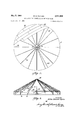
FIGURE 1 is a plan view of a portion of a storage bin which may be constructed with the apparatus of the present invention and in accordance with the instant improved method, the majority of the plates normally presenting the topof the roof section of the bin being removed to illustrate details of the roof trusses and the mechanism for providing a downward force on the roof section, and any.
I the roof section;
'to FIG. 3, but illustrating the way in which a ring is placed around the'lowermost ring supported by the base for the tank prior to the upper section of the tank being is kept to a during lifting thereof;
FIG. 5 a plan view'of thelifting and stabilizing apparatus of the present invention and illustrating in detail the hydraulic connection of the various'pants to a source of fluid under pressure; p I
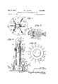
FIG. 6 is an enlarged, fragmentary, vertical, crosssectional view illustrating the connection of one of the. hydraulic lifting units to the side wall of thetank during der, being removed to better illustratethe details of the connector; and 1 FIG. 10 is a fragmentary, plan view'lof the manifold utilized to distribute fluid under pressure to the stabilizer unit and to the hydraulic lift cylinder assemblies respectively. q
The apparatus and process of the present invention are especially useful in facilitating construction of metallic storage tanksor bins of the type generally desigiated 10 in the drawings, and including a conical roof section 12 carried by, and closing the open upper end of a cylindrical wall 14, in turn mounted on and secured to a base 16."
Side wall '14'comprises a number of rings such as 14a and 14b which are formed of a number of rectangular steel plates .18 which are interconnected normally by 7 Welding the adjacent abutting or overlapped extremities, but in certain instances, by bolting and equivalent methods.
The roof. section 12 includes a number of truss sections 20, individual upright legs 22 connected to each truss section 20, and a ring 24 formed of a plurality of plates and connected to legs 22. v
Inconstruction of bin 10, the base 16 is initially laid over a footing on the ground which may comprise gravel,
raised, so that passage of currents of under the tank legs 22,'as well as rail 28 so as to firmly interconnect'the base 16. It is also to be preferredthat a circular, upper rail 28 be welded to the lower extremities of truss units 20 adjacent the zone of merger of legs 22 with the upper rods 20a of corresponding truss units 20, whereby rail 28 not only serves as a means for strengthening roof section 12, but also maintains legs 22 and thereby truss in predetermined radial relationship during subsequent fabrication of tank 10. .Upon oompletion'of the framework of roofsection 12 and comprising truss 20, legs 22 and rail 28, the upper ring 24 is placed around the periphery of roof section 12defined by the lower extremities of truss units 20 and legs 22. in FIG. 3', ring 24 comprises a plunality of rectangular steel plates 26 which are'welded' to one another and to truss 20 and provide means for lifting roof section 12 in a manner hereinafter described.
The rectangular metal roof sheets 30 are welded over truss units 20 in covering relationship thereto as shown in FIG. 1, with sheets 30 being applied either befpre or after fabrication of ring 24. In certain operations, application of sheets 30 to the truss units 20, prior to fabri cation of ring 24, expedites construction of the bin inas-. much as freer access is provided to the plates for weld ing on the upper and lower surfaces thereof. 'In'any event, the roof section 12 is completed while the latteris still disposed on the ground, and including mounting of any vent caps or the like whichare secured tothe'annulus 32 at the central part of the upper domeof roof sand or other aggregate, presenting a relatively smooth 7 surface. Base 16 norm-ally isflconstructed of metallic plates such as 18 which are laid flat on the footing and .welded together to present [a fluid-tight bottom wall.
Normally, no attempt is initially made to out the peripheral edge of base 16 so that the same defines a true circle, with this operation awaiting final fabrication of the bin and thereby welding of the lowermost ring of plates 18 to the upper face of base 16. r V
Next, the roof section 12 is fabricated on base 16 by lowering prefabricated truss units 20 into properdisposisection 12 to permit air to enter the tank. It is also contemplated that suitable cap-means be provided for closring the opening defined by annulus 32, and thus allowing the tank 10 to be filled or emptied through such opening.
' It is also to be understood that additional vents, filler openings and the like, may be provided in the roof '34, presented by sheets 30 as required." It is also content:
plated that roof 34 be painted or otherwise treated with corrosion resistant material while roof section 12 ispo sitioned on base 16, thereby precluding the necessity of workmen-climbing to the top ofthe tank for painting of the same upon final completion of the bin.
The roof section 12 is now in condition forlifting, so that an additional ring, and in this case 14b, maybe added below the ring 24. In order'to accomplish lifting of roof section 12, the apparatus illustrated in'FIG. 3 is placed within the interior of roof section 12 prior to final completion of the ring 24. Thus, it'is to be preferred that one of the plates 26 of ring 24 be omitted until after all of the lifting equipment has been placed with-t (not shown) on the upper extremity 42 thereof. The
lower end of each of the cylinders l8 is reinovably telescoped in a respective support stand broadly numerated 44,- and including an upright tube 46 provided .with'ia number of radially extending base support plates 48 .disposed toengage base 16 as best shown in FIG. 6. An inlet coupling 50 adjacent the upper end'52 of each cylinder 38, has-la hydraulic fluid supply line 54 connected thereto which is in turn secured to, and communicates tion as illustrated'in FIG. 2, and welding the same .to-
gether. The construction of truss unit s 20, and the manner of interconnecting the same is well known in'the art, and may be varied, depending upon the width or span with a respective flexible hydraulic-fluidhose 56. IA
one-way valve is provided in each of the couplings 50' so that when the valve is in one position thereof, fluid may flow into'pthe interior ofa corresponding cylinder 33, but cannot flowoutwardly therefrom. Although not of the tank and the load the same is required to carry,
predetermined spaced relationship from the upper face of illustrated in detail, it is to be understood that a hand control is provided for the valve so that upon shifting of the same to the open position, the fluid'is free to flow outwardly from each cylinder 38 whereby respective pis their. paths tons 40 are returned to the innermost ends of of travel.
Means for supplying hydraulic fluid pressure to As best shown assemblies 36 through corresponding hoses 56, includes a pressure assembly broadly designated 58, and including a reservoir 60, a prime mover 62 which may be either of the electric motor or internal combustion engine type, as well as a hydraulic pump 64 operably coupled to primer mover 62 for operation thereby. A control unit 66 is also carried by resorvoir 60 so that lifting of the completed section of tank can be controlled by a single operator.
The outlet of pump 64 is joined to a fluid manifold 68 by hose 70 with manifold 68 in turn having an outlet coupling 72 for each of the assemblies 36. As illustrated in FIG. 5, hoses 56 are joined directly to corresponding couplings 72 so that hydraulic fluid from pump 64 passes into each of the cylinders 38 under equal pressure. A central coupling 74 mounted on manifold 68 and communicating with hose 70, is connected to the cylinder 76 of stabilizer assembly 78 by a flexible hose 80, in turn releasably connected to L-coupling 82 communicating with the interior of cylinder 76.
As best shown in FIGS. 7 to 9 inclusive, stabilizer unit 78 is provided with a circular base plate 84 secured to the lower extremity of cylinder 76 and supporting the same in an upright position, while three support baifles 86 between the side wall of cylinder 76 and the upper surface of plate 84, prevent tipping of cylinder 76 with respect to plate 84 when a force is applied against the side-thereof or at an angle with respect to base 16. The base plate 84 of unit 78 is releasably anchored to the supporting surface for tank 10 and located substantially on the axis of side wall 14. Piston 88 reciprocably carried by cylinder 76, and extending upwardly therefrom mounts pulley unit 90 on the upper end thereof, provided with a housing 92 thereover and which is carried by the central shaft 94 rotatably carrying a sheave (not shown) for purposes to be outlined.
Three wire rope cables 96, 98 and 100 are adapted to be secured to the roof section 12 and to stabilizer unit 78 respectively, and as indicated in FIGS. 7 and 8, cables 96, 98 and 100 are all passed under corresponding guide structures 102 carried by plate 84, thence trained over the sheave of pulley unit 90 and finally releasably secured to baflles 86 on plate 84.
Each of the guide structures 102 includes a pair of irregularly configured plates 104 and 106 maintained in spaced relationship by an upper transverse wall 108, and a lower spacer 110 interposed between the outwardly extending flanges 112 integral with corresponding plates 104 adjacent the lower extremities thereof and welded or bolted to the upper face of plate 84. Each of the plates 104 and 106 has a circular portion 114 receiving a sheave (not shown) therebetween and rotatable about shaft 116 carried by opposed plates 104 and 106 and spanning the distance therebetween.
The outer, generally triangular portions 118 of plates 104 and 106, have outwardly projecting, arcuate edges 120' which permit corresponding cables 96, 98 and 100 to shift through substantial vertical arcs during the lifting of the completed portion of tank 10, and without contacting the upper walls 108 of each guide structure 102. Elongated, vertical tubes 122 secured to the rearmost portion of each of the guide structures 102, and communicating with the space between plates 104 and 106, slidably receive respective cables 96, 98 and 100, and thereby guide the wire rope toward the sheave of pulley unit 90.
Each of the batfies 86 is provided with an annular member 124 on one face thereof and over which corresponding cables 96, 98 and 100 are adapted to be wound in order to securely afix such cables to stabilizer unit 78. Transversely arcuate clamping blocks 126 are releasably secured to the outer face of each of the annular members 124 in disposition so that the same may be moved into firm clamping engagement with respective wire cables 96, 98 and 100. Bolts 128 releasably securing blocks 126 to an- 6. nular members 124, permit adjustment of blocks 126 so that the length of cables 96, 98 and connected to roof section 12, may be varied as the completed portion of tank 10 is raised from base 16.
Secondary clamp structures are mounted on the outer face of cylinder 76 adjacent the upper extremity thereof for holding cables 96, 98 and 100 in predetermined relationship with respect to stabilizer unit 78 during the time that cables 96, 98 and 100 are being firmly afiixed to batfles 86, through the clamp structures presented by member 124 and blocks 126 thereon.
As shown in FIGS. 8 and 9 each of the clamping structures 130 includes a block 132 secured to the outer face of cylinder 76 and provided with an upright groove 134 therein adapted to receive a portion of a corresponding cable 96, 98 or 100, and externally scored so as to firmly engage the wire rope. A U-shaped member 136 and provided with a pair of legs 138 disposed on opposite sides of a respective block 132 is pivotally secured to the latter by bolt and nut means 140. The bight section 139 integral with the outer extremities of legs 138, is in suflicient spaced relationship to block 132 to clear a second clamping block 142 which is pivotally carried by legs 138 through the medium of bolt and nut means 144. The face of secondary block 142, normally proximal to block 132, also has an upright groove 146 receiving one of the wire ropes with the outer surface of groove 146 also being scored to assure more effective clamping of block 142 to the corresponding cable. Means for biasing each of the blocks 142 toward a corresponding block 132, comprises a pair of arms 148 secured to, and projecting outwardly from the surface of cylinder 76 immediately above a respective block 132. Coil springs 150 between the outer extremities of each of the arms 148 and the ends 152 of bight portion 139, bias the outer portion of U-shaped member 136 of each connector 130 upwardly, whereby corresponding cables 96, 98 and 100 are clamped between blocks 132 and 142.
In order to facilitate lifting of the completed section of tank 10, pipes 154 are preferably secured to the inner surface of each of the rings of side wall 14 and in direct alignment with corresponding assemblies 36. As illustrated in FIG. 6, pipes 154 are secured to a corresponding plate 18 or 26 in spaced relationship thereto by blocks 156. Furthermore, rectangular plates 158 are welded or otherwise secured to corresponding pipes 154 and facing in a direction away from the proximal surface of the side wall 14 of tank 10. Cylindrical sockets 160 integral with plates 158, open downwardly in a manner to receive the upper end of each of the pistons 40.
Inasmuch as the cylinders 36 are normally of greater height, particularly when mounted on respective support stands 44, than the vertical dimension of upper ring 24, it is contemplated that an inner ring be provided on roof section 12 and supported by the lower surfaces of truss sections 20 in concentric relationship with the ring 24. In a typical tank having a diameter of 80 feet, the inner ring (not shown) is preferably disposed at a distance of 10 feet from the inner surface of ring 24 so that cylinder assemblies 36 may be arranged immediately below the inner ring in equally spaced relationship and with the upper extremities 42 of pistons 40 in engagement with suitable sockets provided on the lower surface of the inner ring.
As pointed out previously, the second ring 141) is formed around ring 24 prior to lifting of roof section 12, by disposing plates 18 of ring 14b against the outer surface of plates 26 with abutting ends of such plates being welded into proper position. One of the plates 18 of ring 14b, is temporarily omitted and a cable such as Wire rope 162 is placed around ring 14a with a turnbuckle 164 being employed to snug wire rope 162 against the plates 18 of ring 14b and thereby force such plates into firm, but sliding engagement with plates 26 of ring 24. The tank is now in condition for raising of roof '22, the assemblies 36 are positioned in a circle such as illustrated lll'FIG. 6, and with the lines 54 and hoses 56 connected to manifold 68., The pressure assembly 58 is operably connected to manifold 68 by hose 70 joined to pump 64, and'hose 8b is coupled to coupling 74 of manifold 68 as well as to coupling '72 on stabilizer assembly 795.
' It is to be recognized that stabilizer assembly 78 is positioned .in the exact center of roof section 12, and that cables 96, 98 and 109 are connected to the outer eave ring of roof section 12 at three points in equidistantly spacedtrelationship around the periphery of ring 24. In other words, cables 96, 98 and 109 are releasably secured to roof section'12at zero degrees, 120 degrees and 240 degrees around the circumference of'the periperal margin of roof 34. The longitudinal lengths of cables 95, 98 and 1% are then passed downwardly through respective guides 162 with the" free ends of the cables then being passed around the pulleys carried by V shafts 116 and then upwardly through tubes 122 as indicated in FIG. 8. The piston 88 is initially moved to an extended position-somewhat below the uppermost end 1 of the path of travel thereof, whereby the cables 96, 98
and 1% are passed over the sheave carried by pulley unit of cables 96, 98 and 100.
Shifting of blocks 126 into engagement with cables 96, 98 andlhi), snugs the'same down against the members 124 to prevent movement of the cables with respect to cylinder 76. Fluid pressure is then placed on cylinder v 76 through hose 89, whereby piston 38 is forced upwardly to place equal tension on the cables96, 93 and 100. Thus, all three cables 96, 98 and 10% must be' equally tightened and wrapped around and clamped on annular members'124 prior to raising of roof section 12 with cylinder assemblies 36. Although not illustrated in'FIG. 8 it is to be understood that the free ends of cables 96, 93 and 109 are much longer than. illustrated when the normally uppermost portions of the tank are being raised to compensate for addition to the height of the tank during fabrication thereof. within cylinder 76 is determined by the pressure produced by pump 54 inasmuch as cylinder 76 communicates directly with manifold 62% asoutlined above.
Next, the one-way valves in respective couplings 50, are
opened so that hydraulic fluid is permitted to flow into the upper ends of cylinders 38 and thereby effect displacement of pistons 49 from cylinders 38. The diameters of pistons within, cylinders 38, and the diameter of piston fi within cylinders 76, are so correlated that the total force exerted by all of the cylinder assemblies 36, overcomes the weight of roof section 12, including ring 24 and the downward force applied by cables 95, 93 and 1% which pass over the sheave carried by pulley unit 943 and which thereby prevents roof'section 12 from 12 as soon as the lower margin of ring 24 clears the uppersurface of base 16. It has been found that the provision;v of stabilizer unit 78, including cables 96, 98 and 10 0, connected at three equal points around the periphery of roof section 12, permits fabrication in winds of relatively high velocity, although it can be appreciated that for absolute safety, construction of tankswith the present apparatus should be suspended during very high winds or the like.
for safety reasons. p
'It is to be recognized that the ring 14b prevents substantial currents of air from passing under roof section 12 during raising thereof, inasmuch as the only opening in ring 14b is provided by the missing plate 18. Thus, telescoping of ring 24 out of ring 1412,- proceeds smoothly and with the plates 18 of ring 14b being in position for in1 mediate welding to plates 26 as soon as roof section 12 has been raised to a proper level. It is to be noted that the height to which roof section 12 is raised'with respect to ring 141), depends upon whether the rings are to be butt-welded or connected in overlapping relationship as. illustrated in FIG. 6. After welding of all of the plates 18 of ring 14b to ring 24, and which were present during raising of roof section 12, the final plate 18 is moved into position and welded in place.
The roof section 12 and upperring 14b are nowin condition for being raised to permit placement of ring 14a in its proper position and it can be seen that the plates 18 of ring 14a should be welded into position around ring 14b .with the exception of one plate and then snugged into proper disposition by wire rope 162- and turnbuckle 164. It can be seen that placement of the next successive ring around the most recently completed ring, permits utilization of the latter as a form or jig for the next ring, and materially speeds up the operation. 7
As previously pointed out, tubes 154 are welded to the inner face of ring 14b so that the upper extremities of pistons 49 may be placed in sockets 160 carried by plates 158 welded to tubes 154. Thus, when roof section 12 and blies 36, the latter are moved outwardly into proximal relationship to the inner surface of ring 14b as indicated The force against piston 88 i moving upwardly until piston 88 shiftsdownwardly into cylinder 76 against the pressure of hydraulic fluid forced into the upper end of cylinder 76 from pump 64; a a
Generally speaking, the total area of pistons 40 within cylinders 38 and calculated transversely thereof, exceeds the total area of piston 88 within cylinder 76, although under certain applicationsrthe reverse may be true. In anyevent, cylinder assemblies 36 efiect lifting of the 12 moves upwardly and-yawing, creeling, pitching and rotation of the roof section 12 is prevented in response to currents of wind which pass under the roof section inF-IG. 6. The cables 96, 98 and 100 are readjusted on stabilizer assembly 76 so that piston 88 is again returned to substantially the uppermost end of its path of travel and with equal tension being placed'on cables 96,98 and 1%, it being pointed out that the outer extremities of the latter remain affixed to roof section 12 in the initial positions thereof. r I,
Successive rings are placed around the side wall 14 or" tank 1% and the fabricated portion of the tank lifted in accordance with the procedure outlined in detail above, As the wall 14 increasesin height, additional tubes 154 are secured to the inner surfaces of respective n'ngsofi side wall'14, or the tubes 154 are cut from blocks 156' and moved downwardly to the next ring -therebelow,'. de-
pending upon whether it isdesired to leave tubes 154 within the tank upon completion thereof, or it is contemplated that such tubes 154 be left in place as an economic matter with respect totthe labor involved in moving tubes 154.
After the final ring of side wall 14 is in place, the assemblies 36, stabilizer units 76, and pressure assembly 53 are removed from the tank immediately prior to welding of the last plate of the lowermost ring imposition, The lower edge of the bottom ring may. then be welded to base 16 and the same cut to proper circular configura- Iroof section 12, and particularly the horizontal circular seams definedby the respective rings of side wall 14.
Thus, persons fabricating the tank are permitted to work a substantially at ground level and welding rigs mounted on circular tracks around the circumference of base-16,
may be employed to interconnect the plates of side wall 14 without the necessity of moving the tracks for the welding rigs throughout the tank construction operation.
Having thus described the invention, what is claimed as new and desired to be secured by Letters Patent is:
1. Apparatus for expediting the construction of a storage bin on a supporting surface therefor and having a series of tubular members positioned in interconnected, superimposed, stacked relationship presenting a side Wall, and a roof section overlying and carried by said side wall, said apparatus including a plurality of fluid-actuated, extensible units comprising first single-acting piston and cylinder assemblies and each having a first segment adapted to rest on the supporting surface for the bin, and a second segment adapted to be releasably connected to circumferentially located areas of the tubular member and in substantially equidistantly spaced relationship therearound; fluid supply means operably connected to each of said units for directing fluid thereinto to shift one of the segments relative to the other segment of each unit whereby the tubular member and roof section are shifted away from said supporting surface during operation of said fluid supply means; stabilizing mechanism releasably secured to said supporting surface centrally of the tubular member and including a second singleacting piston and cylinder assembly having a cylinder and a shiftable piston provided with a pulley thereon, and further including a plurality of elongated extensible cable elements adapted to be secured to said roof section at a plurality of points in equidistant, spaced relationship from the axis of the roof section, and hydraulically actuated restraining structure coupled to said elements for placing a predetermined tension on the same to restrict extension of the elements during movement of the tubular member and roof section away from the supporting surface and of somewhat less pressure than the upward force exerted on the tubular member by said units whereby the tubular member and said roof section are raised from said supporting surface a distance determined by the extent of correlated extension of said units and the cable elements during operation of said fluid supply means, and wherein said cable elements are connected to said second cylinder assembly and trained over said pulley in a direction requiring shifting of the piston member relative to said cylinder to permit extension of the effective lengths of said cable elements as the tubular member and roof section are shifted upwardly by said units.
2. Apparatus as set forth in claim 1, wherein the total surface area of the piston in said second assembly transversely of the cylinder thereof is somewhat less than the total surface areas of the pistons of said first assemblies calculated transversely of the same.
3. Apparatus as set forth in claim 2, wherein said fluid supply means is connected to said first and second assemblies and is provided with a common fluid supply source under predetermined pressure suficient to effect raising of said tubular member and the roof section.
4. Apparatus as set forth in claim 1, wherein is provided primary coupling means on the cylinder of the second assembly for releasably connecting respective cable elements to the second assembly at any point along the longitudinal length thereof.
5. Apparatus as set forth in claim 2, wherein is provided secondary quick release coupling means on said second assembly engageable with each of the cable elements for holding the latter under a predetermined tension when connected to said roof section until the cable elements can be secured to the second assembly by respective primary coupling means.
6. Apparatus as set forth in claim 4, wherein is provided means adjacent the lower portion of said second assembly for receiving a stretch of each of the cables intermediate said pulley on the piston of said second assembly and corresponding extremities of the cable elements adapted to be connected to said roof section.
7. Apparatus as set forth in claim 1, wherein is provided at least three cable elements connected to said second assembly and extending outwardly therefrom along imaginary radians describing substantially equal arcs therebetween.
References Cited in the file of this patent UNITED STATES PATENTS 451,775 Satterlee et a1 May 5, 1891 1,221,723 Guichard Apr. 3, 1917 1,325,053 Steidle Dec. 16, 1919 1,839,578 Morton Jan. 5, 1932 2,449,781 Jameson et al Sept. 21, 1948 2,605,540 Kroll et a1 Aug. 5, 1952 2,732,177 Ludowici Jan. 24, 1956 2,763,467 Doolittle et al Sept. 18, 1956 2,919,896 Wurst Ian. 5, 1960 2,993,679 Morgan July 25, 1961 OTHER REFERENCES Engineering NewsRecord, Feb. 17, 1957 (pages 26 and 27 Architectural Record, March 1957 (pages 251-254).
Claims (1)
1. APPARATUS FOR EXPEDITING THE CONSTRUCTION OF A STORAGE BIN ON A SUPPORTING SURFACE THEREFOR AND HAVING A SERIES OF TUBULAR MEMBERS POSITIONED IN INTERCONNECTED, SUPERIMPOSED, STACKED RELATIONSHIP PRESENTING A SIDE WALL, AND A ROOF SECTION OVERLYING AND CARRIED BY SAID SIDE WALL, SAID APPARATUS INCLUDING A PLURALITY OF FLUID-ACTUATED, EXTENSIBLE UNITS COMPRISING FIRST SINGLE-ACTING PISTON AND CYLINDER ASSEMBLIES AND EACH HAVING A FIRST SEGMENT ADAPTED TO REST ON THE SUPPORTING SURFACE FOR THE BIN, AND A SECOND SEGMENT ADAPTED TO BE RELEASABLY CONECTED TO CIRCUMFERENTIALLY LOCATED AREAS OF THE TUBULAR MEMBER AND IN SUBSTANTIALLY EQUIDISTANTLY SPACED RELATIONSHIP THEREAROUND; FLUID SUPPLY MEANS OPERABLY CONNECTED TO EACH OF SAID UNITS FOR DIRECTING FLUID THERINTO TO SHIFT ONE OF THE SEGMENTS RELATIVE TO THE OTHER SEGMENT OF EACH UNIT WHEREBY THE TUBULAR MEMBER AND ROOF SECTION ARE SHIFTED AWAY FROM SAID SUPPORTING SURFACE DURING OPERATION OF SAID FLUID SUPPLY MEANS; STABILIZING MECHANISM RELEASABLY SECURED TO SAID SUPPORTING SURFACE CENTRALLY OF THE TUBULAR MEMBER AND INCLUDING A SECOND SINGLE-ACTING PISTON AND CYLINDER ASSEMBLY HAVING A CYLINDER AND A SHIFTABLE PISTON PROVIDED WITH A PULLEY THEREON, AND FURTHER INCLUDING A PLURALITY OF ELONGATED EXTENSIBLE CABLE ELEMENTS ADAPTED TO BE SECURED TO SAID ROOF SECTION AT A PLURALITY OF POINTS IN EQUIDISTANT, SPACED RELATIONSHIP FROM THE AXIS OF THE ROOF SECTION, AND HYDRAULICALLY ACTUATED RESTRAINING STRUCTURE COUPLED TO SAID ELEMENTS FOR PLACING A PREDETERMINED TENSION ON THE SAME TO RESTRICT EXTENSION OF THE ELEMENTS DURING MOVEMENT OF THE THE TUBULAR MEMBER AND ROOF SECTION AWAY FROM THE SUPPORTING SURFACE AND OF SOMEWHAT LESS PRESSURE THAN THE UPWARD FORCE EXERTED ON THE TUBULAR MEMBER BY SAID UNITS WHEREBY THE TUBULAR MEMBER AND SAID ROOF SECTION ARE RAISED FROM SAID SUPPORTING SURFACE A DISTANCE DETERMINED BY THE EXTENT OF CORRELATED EXTENSION OF SAID UNITS AND THE CABLE ELEMENTS DURING OPERATION OF SAID FLUID SUPPLY MEANS, AND WHEREIN SAID CABLE ELEMENTS ARE CONNECTED TO SAID SECOND CYLINDER ASSEMBLY AND TRAINED OVER SAID PULLEY IN A DIRECTION REQUIRING SHIFTING OF THE PISTON MEMBER RELATIVE TO SAID CYLINDER TO PERMIT EXTENSION OF THE EFFECTIVE LENGTHS OF SAID CABLE ELEMENTS AS THE TUBULAR MEMBER AND ROOF SECTION ARE SHIFTED UPWARDLY BY SAID UNITS.
Priority Applications (1)
| Application Number | Priority Date | Filing Date | Title |
|---|---|---|---|
| US63030A US3131908A (en) | 1960-10-17 | 1960-10-17 | Apparatus for constructing metallic bins |
Applications Claiming Priority (1)
| Application Number | Priority Date | Filing Date | Title |
|---|---|---|---|
| US63030A US3131908A (en) | 1960-10-17 | 1960-10-17 | Apparatus for constructing metallic bins |
Publications (1)
| Publication Number | Publication Date |
|---|---|
| US3131908A true US3131908A (en) | 1964-05-05 |
Family
ID=22046450
Family Applications (1)
| Application Number | Title | Priority Date | Filing Date |
|---|---|---|---|
| US63030A Expired - Lifetime US3131908A (en) | 1960-10-17 | 1960-10-17 | Apparatus for constructing metallic bins |
Country Status (1)
| Country | Link |
|---|---|
| US (1) | US3131908A (en) |
Cited By (13)
| Publication number | Priority date | Publication date | Assignee | Title |
|---|---|---|---|---|
| US3199839A (en) * | 1962-10-31 | 1965-08-10 | Smith Harvestore Products | Apparatus for erecting storage structures |
| US4177915A (en) * | 1978-06-19 | 1979-12-11 | Wikstrom International Ab | Method for manufacturing large tanks |
| US5271604A (en) * | 1992-09-15 | 1993-12-21 | Bruno De Castro | Support structure for lifting tanks with roof column supports |
| US6299137B1 (en) | 1999-04-28 | 2001-10-09 | Wesley Allen Bainter | Hydraulic grain storage bin lifting system |
| US20100083593A1 (en) * | 2008-10-07 | 2010-04-08 | Accu Steel, Inc. | Coned Storage Dome |
| US7743582B1 (en) * | 2004-10-04 | 2010-06-29 | Davor Petricio Yaksic | Conical roof construction |
| WO2012004440A1 (en) * | 2010-07-07 | 2012-01-12 | Cantoni Gruas Y Montajes S.R.L. | Method for constructing tanks and device for performing the hoop-spacing step of said method |
| US20120217364A1 (en) * | 2009-10-16 | 2012-08-30 | Jansens & Dieperink B.V. | Device and method for positioning shell parts |
| US20150033640A1 (en) * | 2012-04-04 | 2015-02-05 | Cantoni Gruas Y Montajes S.R.L. | Process for building a tank and devices for executing the process |
| US20150197953A1 (en) * | 2012-11-06 | 2015-07-16 | Ihi Corporation | Method for constructing cylindrical tank |
| US20160083957A1 (en) * | 2013-06-27 | 2016-03-24 | Ihi Corporation | Method for constructing cylindrical tank |
| US9718656B2 (en) | 2013-07-08 | 2017-08-01 | Bainter Construction Services, Llc | Jack with two masts |
| US11248388B2 (en) * | 2019-05-20 | 2022-02-15 | Ctb, Inc. | Commercial hopper grain bin assembly method |
Citations (10)
| Publication number | Priority date | Publication date | Assignee | Title |
|---|---|---|---|---|
| US451775A (en) * | 1891-05-05 | Borough | ||
| US1221723A (en) * | 1911-10-07 | 1917-04-03 | Mors Electricite | Telescopic mast. |
| US1325053A (en) * | 1919-12-16 | Telescoping tower | ||
| US1839578A (en) * | 1929-04-15 | 1932-01-05 | Western Gas Construction Co | Method of erecting tanks |
| US2449781A (en) * | 1944-03-18 | 1948-09-21 | Bethlehem Steel Corp | Apparatus for lifting massive objects |
| US2605540A (en) * | 1950-03-18 | 1952-08-05 | Smith Corp A O | Method of erecting storage structures |
| US2732177A (en) * | 1956-01-24 | ludowici | ||
| US2763467A (en) * | 1954-07-02 | 1956-09-18 | Donald B Doolittle | Constant tension winch |
| US2919896A (en) * | 1956-11-13 | 1960-01-05 | Chicago Bridge & Iron Co | Apparatus for raising tank shells |
| US2993679A (en) * | 1959-02-20 | 1961-07-25 | Morgan John Sydney | Hoisting apparatus for cylindrical tanks |
-
1960
- 1960-10-17 US US63030A patent/US3131908A/en not_active Expired - Lifetime
Patent Citations (10)
| Publication number | Priority date | Publication date | Assignee | Title |
|---|---|---|---|---|
| US451775A (en) * | 1891-05-05 | Borough | ||
| US1325053A (en) * | 1919-12-16 | Telescoping tower | ||
| US2732177A (en) * | 1956-01-24 | ludowici | ||
| US1221723A (en) * | 1911-10-07 | 1917-04-03 | Mors Electricite | Telescopic mast. |
| US1839578A (en) * | 1929-04-15 | 1932-01-05 | Western Gas Construction Co | Method of erecting tanks |
| US2449781A (en) * | 1944-03-18 | 1948-09-21 | Bethlehem Steel Corp | Apparatus for lifting massive objects |
| US2605540A (en) * | 1950-03-18 | 1952-08-05 | Smith Corp A O | Method of erecting storage structures |
| US2763467A (en) * | 1954-07-02 | 1956-09-18 | Donald B Doolittle | Constant tension winch |
| US2919896A (en) * | 1956-11-13 | 1960-01-05 | Chicago Bridge & Iron Co | Apparatus for raising tank shells |
| US2993679A (en) * | 1959-02-20 | 1961-07-25 | Morgan John Sydney | Hoisting apparatus for cylindrical tanks |
Cited By (19)
| Publication number | Priority date | Publication date | Assignee | Title |
|---|---|---|---|---|
| US3199839A (en) * | 1962-10-31 | 1965-08-10 | Smith Harvestore Products | Apparatus for erecting storage structures |
| US4177915A (en) * | 1978-06-19 | 1979-12-11 | Wikstrom International Ab | Method for manufacturing large tanks |
| US5271604A (en) * | 1992-09-15 | 1993-12-21 | Bruno De Castro | Support structure for lifting tanks with roof column supports |
| US6299137B1 (en) | 1999-04-28 | 2001-10-09 | Wesley Allen Bainter | Hydraulic grain storage bin lifting system |
| US6311952B2 (en) * | 1999-04-28 | 2001-11-06 | Wesley Allen Bainter | Hydraulic grain storage bin lifting system and method |
| US6641115B1 (en) | 1999-04-28 | 2003-11-04 | Wesley Allen Bainter | Bin lifting system |
| US7743582B1 (en) * | 2004-10-04 | 2010-06-29 | Davor Petricio Yaksic | Conical roof construction |
| US20100083593A1 (en) * | 2008-10-07 | 2010-04-08 | Accu Steel, Inc. | Coned Storage Dome |
| US9334665B2 (en) * | 2009-10-16 | 2016-05-10 | J&D Beheer B.V. | Device and method for positioning shell parts |
| US20120217364A1 (en) * | 2009-10-16 | 2012-08-30 | Jansens & Dieperink B.V. | Device and method for positioning shell parts |
| WO2012004440A1 (en) * | 2010-07-07 | 2012-01-12 | Cantoni Gruas Y Montajes S.R.L. | Method for constructing tanks and device for performing the hoop-spacing step of said method |
| US9133640B2 (en) * | 2012-04-04 | 2015-09-15 | Cantoni Gruas Y Montajes S.R.L. | Process for building a tank and devices for executing the process |
| US20150033640A1 (en) * | 2012-04-04 | 2015-02-05 | Cantoni Gruas Y Montajes S.R.L. | Process for building a tank and devices for executing the process |
| US20150197953A1 (en) * | 2012-11-06 | 2015-07-16 | Ihi Corporation | Method for constructing cylindrical tank |
| US9546495B2 (en) * | 2012-11-06 | 2017-01-17 | Ihi Corporation | Method for constructing cylindrical tank |
| US20160083957A1 (en) * | 2013-06-27 | 2016-03-24 | Ihi Corporation | Method for constructing cylindrical tank |
| US9556607B2 (en) * | 2013-06-27 | 2017-01-31 | Ihi Corporation | Method for constructing cylindrical tank |
| US9718656B2 (en) | 2013-07-08 | 2017-08-01 | Bainter Construction Services, Llc | Jack with two masts |
| US11248388B2 (en) * | 2019-05-20 | 2022-02-15 | Ctb, Inc. | Commercial hopper grain bin assembly method |
Similar Documents
| Publication | Publication Date | Title |
|---|---|---|
| US3131908A (en) | Apparatus for constructing metallic bins | |
| US7004737B2 (en) | Methods and apparatus for forming concrete structures | |
| US7500592B1 (en) | Storage tank construction | |
| CN107697818B (en) | Construction method and special construction equipment for wall of prestressed concrete wind power tower | |
| US4040774A (en) | Apparatus for constructing concrete walls | |
| CN112938774B (en) | Integral hoisting system and hoisting method for assembly type component | |
| US3779678A (en) | Apparatus for constructing concrete walls | |
| US6213319B1 (en) | Powered lifting apparatus using multiple booms | |
| US4614251A (en) | Load raising vehicle and method | |
| US4496277A (en) | Lifting device and method | |
| US3057054A (en) | Method for erecting steel tanks and similar enclosed structures | |
| US3486583A (en) | Arrangement at vertically adjustable stands | |
| US2287197A (en) | Method of constructing horizontal cylindrical tanks | |
| US2993679A (en) | Hoisting apparatus for cylindrical tanks | |
| US2998106A (en) | Mobile elevating and erecting device for masts assembled from separate sections | |
| US4696135A (en) | Method and apparatus for constructing towers | |
| US7066343B1 (en) | Powered lifting apparatus using multiple booms | |
| JP2859163B2 (en) | Rotary erection method for bridges with high piers | |
| US2414310A (en) | Method of building concrete oil storage tanks | |
| CN213015280U (en) | Movable material loading platform | |
| US3366251A (en) | Climbing crane | |
| US4505397A (en) | Apparatus for hoisting materials and placing concrete | |
| CN214247190U (en) | Vertical storage tank ladder | |
| US3778204A (en) | Apparatus for erecting concrete structures | |
| US3187838A (en) | Scaffolding structure |