US3085656A - Lift truck constructed from detachably connected parts - Google Patents
Lift truck constructed from detachably connected parts Download PDFInfo
- Publication number
- US3085656A US3085656A US22265A US2226560A US3085656A US 3085656 A US3085656 A US 3085656A US 22265 A US22265 A US 22265A US 2226560 A US2226560 A US 2226560A US 3085656 A US3085656 A US 3085656A
- Authority
- US
- United States
- Prior art keywords
- members
- lifting
- side frame
- vehicle
- track
- Prior art date
- Legal status (The legal status is an assumption and is not a legal conclusion. Google has not performed a legal analysis and makes no representation as to the accuracy of the status listed.)
- Expired - Lifetime
Links
Images

Classifications
-
- B—PERFORMING OPERATIONS; TRANSPORTING
- B62—LAND VEHICLES FOR TRAVELLING OTHERWISE THAN ON RAILS
- B62B—HAND-PROPELLED VEHICLES, e.g. HAND CARTS OR PERAMBULATORS; SLEDGES
- B62B1/00—Hand carts having only one axis carrying one or more transport wheels; Equipment therefor
- B62B1/18—Hand carts having only one axis carrying one or more transport wheels; Equipment therefor in which the load is disposed between the wheel axis and the handles, e.g. wheelbarrows
- B62B1/20—Hand carts having only one axis carrying one or more transport wheels; Equipment therefor in which the load is disposed between the wheel axis and the handles, e.g. wheelbarrows involving parts being collapsible, attachable, detachable or convertible
-
- B—PERFORMING OPERATIONS; TRANSPORTING
- B62—LAND VEHICLES FOR TRAVELLING OTHERWISE THAN ON RAILS
- B62B—HAND-PROPELLED VEHICLES, e.g. HAND CARTS OR PERAMBULATORS; SLEDGES
- B62B3/00—Hand carts having more than one axis carrying transport wheels; Steering devices therefor; Equipment therefor
- B62B3/02—Hand carts having more than one axis carrying transport wheels; Steering devices therefor; Equipment therefor involving parts being adjustable, collapsible, attachable, detachable or convertible
-
- B—PERFORMING OPERATIONS; TRANSPORTING
- B66—HOISTING; LIFTING; HAULING
- B66F—HOISTING, LIFTING, HAULING OR PUSHING, NOT OTHERWISE PROVIDED FOR, e.g. DEVICES WHICH APPLY A LIFTING OR PUSHING FORCE DIRECTLY TO THE SURFACE OF A LOAD
- B66F9/00—Devices for lifting or lowering bulky or heavy goods for loading or unloading purposes
- B66F9/06—Devices for lifting or lowering bulky or heavy goods for loading or unloading purposes movable, with their loads, on wheels or the like, e.g. fork-lift trucks
Definitions
- one form of the lifting and transport truck of the present invention can be disassembled to a knocked-down condition and easily placed in the trunk of an automobile, or in an out-of-way position in a pick-up vehicle, and thereby moved between diiferent job sites, such as between different office buildings or different warehouses, or the like, as the occasion arises.
- maximum utilization of the lifting and transport apparatus of the present invention can be achieved by reason of the portability afforded by the manner in which the same is constructed.
- a lifting and transport truck comprises a pair of side frame members which are preferably of a tubular construction and a right triangular overall configuration.
- Each of the side frame members mounts a pair of caster units in tandem alignment on the undersides of the side frame members.
- the side frame members are connected together by a lower frame assembly extending between the lower portions of the side frame members and by an upper frame member connecting the upper ends of the side frame members to thereby afford a rigidly braced frame construction.
- the lift apparatus also comprises load-lifting mechanism which includes a track assembly supported on the lower frame assembly.
- the track assembly comprises a pair of vertically extending track members and upper and lower crosspieces connecting the respective upper and lower ends of the track members.
- a fork plate is mounted for vertical movement along the track members by rollers engaged with opposite surfaces of the track members, and lifting forks are removably mounted on the fork plate.
- a ball-screw arrangement is incorporated with the track assembly so that the fork plate and the item to be picked up and transported can be readily elevated with a minimum of effort.
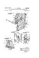
- FIG. 1 is an exploded perspective view illustrating the separate component parts and the manner in which such parts are assembled in a lifting and transport vehicle constructed in accordance with one embodiment of the present invention
- FIG. 2 is a perspective view from the rear of the lifting and transport vehicle illustrated in FIG. 1, showing the vehicle in its assembled condition;
- FIG. 3 is a fragmentary perspective view showing details of the elevating mechanism of the vehicle illustrated in FIG. 2;
- FIG. 4 is an enlarged fragmentary detail view of a portion of frame connecting structure of the vehicle illustrated in FIGS. 1 and 2;
- FIG. 5 is a detail view taken in the direction of the arrows 55 in FIG. 4; and I FIG. 6 is a perspective view of the vehicle illustrated in FIGS. 1 and 2, but showing the elevating mechanism, including the elevatable fork plate, mounted in a position reversed from that illustrated in FIG. 2.
- FIGS. 1 and 2 a lifting and transport truck or vehicle constructed in accordance with one embodiment of the present invention is indicated generally by the reference numeral 21.
- the vehicle 21 comprises a pair of side frame members 22 and 23, each of which is of a triangular overall configuration.
- each of the side frame members 22 and 23 is preferably of a tubular construction so as to obtain a maximum of rigidity with a minimum of weight and bulk.
- a side frame member 22 comprises a vertically extending tubular member 24 and a horizontally extending tubular member 26.
- the members 24 and 26 are joined together at their adjacent ends as by welding so as to define substantially a right angle therebetween.
- the other ends of the members 24 and 26 are interconnected by a tubular member 27 which forms the hypotenuse of the triangular configuration of the side frame member 22. Additionally, a reinforcing member 28 is preferably extended from the connected ends of the members 24 and 26 to the mid-portion of the member 27 to impart additional rigidity to the side frame member.
- a pair of caster units 29 and 31, including wheels 32 and 33, are mounted on the underside of the side frame member 22. The caster units are aligned in tandem with the caster unit 31 supported within the end of the tubular member 24 and the caster unit 29 supported within a sleeve piece 34 attached to the forward end of the side frame member 22.
- the side frame member 23 is generally similar to the side frame member 22 described and includes a vertically extending tubular member 36, a horizontally extending lower tubular member 37, and a third tubular member 39 interconnecting the upper and forward ends of the members 36 and 37.
- the side frame member 23 likewise includes a reinforcing piece 41 as well as a pair of tandem aligned caster units 42 and 43 which include respective wheels 44 and 46.
- the side frame members 22 and 23 are adapted to be associated with additional frame means in the form of a lower cross brace or frame assembly 47 and an upper cross brace or frame member 48.
- the lower frame assembly 47 includes a pair ofparallel and horizontally extending pieces 48 and 49 connected together at their opposite ends by vertically extending angle pieces 51 and 52.
- the pieces 48' and 49 are preferably extruded members of a hollow box-like construction in section so as to keep the weight of the vehicle 21 at a minimum.
- a pair of flat strips 53 are preferably extended between the pieces 48' and 49 at spaced intervals to add additional reinforcement for the frame assembly 47.
- inclined struts 54 are joined to the upwardly extending portions of the angle pieces 51 and 52 and the upper surface of the piece 48 to brace the upwardly extending portions of the angle pieces 51 and 52.
- the top frame member 48 comprises a pair of spaced apart and horizontally extending pieces 56 and 57 interconnected at their adjacent ends by connecting strips 58 and 59.
- the pieces 56 and 57 may also preferably be of an extruded and hollow construction.
- the side frame members 22 and 23 are adapted to be connected to the lower frame assembly 47 and the upper frame member 48 in a rapid and quite simple manner, but in a manner such that a quite rigid structure is nevertheless obtained.
- the means for connecting the lower frame assembly 47 and the side frame members include flanges 61 and 62 which are integrally attached to the respective tubular members 24 and 36 of the side frame members 22 and 23.
- the angle strips 51 and 52 of the lower frame assembly 47 include projecting flanges 51A and 52A which are complementary to and are adapted to be engaged with the mating flanges 61 and 62.
- the respective flanges 61 and 62 are formed with openings '63 and 64 of a keyhole shape in the upper and lower end portions thereof, while the flanges 52A and 51A are formed with circular openings 66 and 67.
- fastening means which include a bolt 71 having a head portion 71H, a wing nut 72, and a spacer sleeve or washer 73, are adapted to be associated with the flanges of the side frame members and the lower frame assembly to maintain such flanges in clamped engagement with one another.
- the shank of a bolt 71 extends through an opening 66 of the flanges 51A with the head 71H of the bolt spaced from the rearward surface of the flange.
- the enlarged portion of the keyhole opening 64 of the flange 62 of the lower frame assembly can be readily passed over the head 71H of the bolt and the bolt and flange 51A moved downwardly with respect to the flange 62 until the under surface of the bolt head engages the rearward surface of the flange 62 in the area adjacent the reduced diameter portion of the keyhole opening. Subsequently, the wing nut 72 is turned down to clamp the respective flanges of the side frame member and the lower frame member together, whereupon the two frame components are securely connected to one another.
- Connecting structure for connecting the upper ends of the side frame members 22 and 23 with the upper frame member 48 in a simple and rapid manner is also incorporated in the vehicle 21 of the present invention. While, as will be described in greater detail hereinbelow, the upper frame member 48 is not connected to the side frame members 22 and 23 until after a load-elevating mechanism, indicated generally by the reference numeral 81 in FIG. 2, has been mounted on the lower frame assembly 47, it may be noted at this time that such connecting means include upwardly projecting flanges 73 and 74 at the upper ends of the side frame members 22 and 23.
- the flanges 73 and 74 are formed with respective slots 73S and 745 in their upper edges, and such slots are adapted to receive studs 76 and 77 which project from the end pieces 58 and 59 of the upper frame member 48.
- Wing nuts 78 are threaded on the outer ends of the studs 76 and 77 for clamping the flanges 73 and 74 to the respective end pieces 58 and 59 of the upper frame member 48.
- the lifting and transport apparatus of the present invention includes a lifting mechanism 81 which is adapted to be supported on the lower frame assembly 47, as noted generally hereinabove.
- the lifting mechanism 81 is, like the other component parts of the vehicle 21, free of projecting parts which would hinder compact stacking and storage of the component parts of the vehicle 21 in the disassembled condition.
- the lifting mechanism 81 comprise-s three main partsa track assembly 82, a load-carrying lift plate 83 which is vertically movable along the track assembly 82, and a ballscrew mechanism 84 (see FIG. 2) for moving the plate 83 along the track assembly 82.
- the track assembly 82 comprises a pair of vertically extending track members in the form of upright bars 86 and 87 joined at their lower and upper ends by cross pieces 88 and 89.
- the track members 86 and 87 are preferably angle pieces as illustrated.
- the track assembly 82 also includes a support member 91 which is best iilustrated in FIG. 3.
- the support member 91 extends be tween and is connected to the track members 86 and 87 adjacent the lower ends thereof, and gussets as 92 are preferably utilized as illustrated in FIG. 3 for bracing the support member on the track members.
- the support member 91 is in the form of an angle bar and hence includes a depending flange 91F so as to afford a saddle for supporting the lifting mechanism 81 from the upper cross piece 48 of the frame assembly 47.
- the lifting mechanism 81 is assembled with the frame assembly 47 merely by positioning the support member 91 on the cross piece 48.
- the lifting mechanism 81 be pre-' vented from shifting laterally on the frame assembly 47 during operation of the vehicle 21, and for this purpose aligning means, which include a pin 93, are incorporated in the frame assembly 47 so as to project upwardly from the upper surface of the cross piece 48.
- the support member 91 is formed with an opening adapted to receive the projecting portion of the pin 93 so that in the assembled condition, as illustrated in FIG. 3, the lifting mechanism 81 is maintained in a predetermined position with respect to the side frame members 22 and 23.
- cross piece 89 of the track assembly 82 is preferably provided with spaced openings 94 (see FIG. 1) which are adapted to receive corresponding and downwardly projecting pins (not illustrated) incorporated in the upper frame member 48.
- the plate 83 includes rollers which are engaged with opposite surfaces of the track members 36 and 87 to enable the plate 83 to move vertically along the track members 86 and 87 with a minimum of friction.
- a strip 96 is attached to the rear surface of the plate 83 in alignment with each of the track members 86 and 87, and a roller 97 is journalled for rotation on a shaft 98 supported by the strip 96.
- a portion of the track member 86 is partially broken away in FIG. 3 to illustrate this construction.
- Rollers 99 engage the surfaces of the track members 86 and 87 opposite that engaged by the rollers 97, and the rollers 99 are carried by support strips 101 attached to the plate 83 adjacent the upper edge thereof.
- Lifting forks 102 are removably mounted on the plate 8 3, and for this purpose brackets 102 and 103 are formed on the rearward surface of the plate 83.
- brackets 102 and 103 are formed on the rearward surface of the plate 83.
- the vertically extending leg of each fork 102' is insertable through the brackets 103 and '102 and a pin 104 is thereafter inserted through a suitable opening formed in the upper end of the fork and above the bracket 102 to retain the fork in the assembled position illustrated in FIGS. 2 and 3.
- the rear surface of the fork plate 83 includes a projec'ting flange 6 which affords a mount for a nut 107 of the ball-screw mechanism 84.
- the nut 10 7 is rigidly attached to the flange 106, which in turn is preferably reinforced by braces 108.
- the ball-screw mechanism 84 also includes a vertically extending and externally threaded lead screw 109 which is supported at its lower end on the cross piece 88 of the track assembly 82 (see FIG. 1). At its upper end portion the screw 109 is supported against sideways movement by a U-shaped bracket 111 attached to the underside of the cross piece 89 of the track assembly 82.
- the bracket 111 is additionally connected to the rail members 8'6 and 87 by a pair of diagonal braces 112.
- the uppermost end of the screw 109 is formed with a hexhead 113.
- a crank 114 (see FIG. 1) includes a handle 114H and a socket 1148 which fits on the hexhead 113.
- the screw 109 is rotated in the desired direction by the crank 114.
- the ball-screw mechanism 84 and the rollers 97 and 99' present a minimum of friction, only a small amount of effort is required to elevate relatively heavy loads.
- the means for elevating the fork plate 83 has been illustrated as a manually actuated ball-screw mechanism, it will be recognized that the lead screw 109 could as well be power driven, as by an electric motor suitably mounted on the track assembly 82. Also other elevating apparatus could equally well be used. Thus, by way of example, a hydraulically actuated arrangement incorporating a manually actuated or motor driven pump could be used if desired to elevate the fork plate 83.
- the upper surface of the forks 102 are formed with a gripping surface which minimizes any tendency of the load to slide or shift on the forks.
- a gripping surface is afforded by beads of weldment W distributed along the upper surfaces of the fork 102 as shown in the enlarged detail in FIG. 3.
- Such beads of weldment are disposed on the forks .102 by drawing a welding rod along the length of the forks 102 in several successive passes and at a rate of travel which is insufiicient to enable a conventional or continuous weld deposit to be formed.
- the side frame members 22 and 23 are first of all connected to the lower frame assembly 47 by the fastening bolts associated with the respective flanges 61 and 62 of the side frame members and the flanges 51A and 52A of the lower frame assembly.
- the lifting mechanism 81 is mounted on the lower frame assembly 47 by the saddle arrangement afforded by the support member 91.
- the upper frame member 48 is connected to the side frame members 22 and 23, and the forks 102 are mounted on the fork plate 83.
- the vehicle can be knocked down in a simple and rapid manner in a sequence opposite that described immediately above. Thereafter, the component parts of the vehicle 21 can be stacked together in a compact manner in an automotive trunk or pick-up vehicle to facilitate transportation of the vehicle 21 between different job sites.
- the lifting mechanism 81 can be assembled in a position reversed from that illustrated in FIGS. 1 and 2 so that the fork plate 83 and forks 102 face to the rear. This is the disposition illustrated in FIG. 6 and enables free vertical movement of the fork plate and forks and load carried thereby without any obstruction by the side frame members 22 and 23.
- ballast such as bags 121 are added to the vehicle 21 to counteract any tendency toward unbalance caused by reason of the off-center disposition of the load with respect to the wheels.
- the opensided tubular construction utilized in the frame members 22 and 23- facilitate the use of boards or the like for supporting such ballast.
- a lightweight lifting and transport vehicle adaptable for ready assembly from and disassembly to a knocked-down condition in which all component parts of the vehicle can be stored and stacked flat to afford a compact arrangement of minimum bulk, whereby movement of the lifting and transport vehicle bet-ween job sites is facilitated
- said lifting and transport vehicle comprising: a pair of spaced substantially flat and separate side frame members of substantially identical construction and each inclusive of a flange and wheels; wholly separate frame members of substantially flat form extending between and separating said side frame members; connecting means secured to the ends of the frame means for attaching opposite ends of said frame means detachably to the flanges of said side frame members; and elevating means for lifting a load, said elevating means including vertically extending track members included as a part of a substantially flat vertical frame member removably supported as a separate member on said frame means, a wholly separate plate member removably associated with said elevating means and having rollers engaged with opposite surfaces of said track members and movable vertically therealong,
- a lifting and transport vehicle adaptable for ready assembly from and disassembly to a knocked-down condition in which all component parts of the vehicle can be stored and stacked flat to afford a compact arrangement of minimum bulk, whereby movement of the lifting and transport vehicle between job sites is facilitated
- said lifting and transport vehicle comprising: a pair of spaced wholly separate and substantially flat side frame members of substantially identical tubular construction and including wheel means mounted on the undersides thereof; each of said frame members including an attaching element rigidly secured thereto; frame means extending etween said side frame members and comprising a lower frame assembly having attaching elements rigidly secured thereto and adapted to be detachably interconnected with the first-named attaching elements of said side frame members, and an upper frame member adapted to be detachably connected to upper ends of said side frame members to thereby afford a rigidly braced structure; said lower and upper frame member each being separately constructed and substantially fiat; and elevating means for lifting a load, said elevating means including vertically extending track members rigid
- a lifting and transport vehicle as defined in claim 2 including aligning means comprising complementary formed pin and locating holes in said track assembly and lower frame assembly and upper frame member for retaining said track assembly in a fixed position between said side frame members.
- a lifting and transport vehicle adaptable for ready assembly from and disassembly to a knock-down condition in which all component parts of the vehicle can be stored and stacked flat to afford a compact arrangement of minimum bulk, whereby movement of the lifting and transport vehicle between job sites is facilitated
- said lifting and transport vehicle comprising: a pair of separate substantially flat side frame members of substantially identical triangular configuration having wheel means mounted on the undersides thereof; separately constructed substantially fiat frame means extending between and separating said side frame members; connecting means for attaching opposite ends of said frame means to said side frame members and including interfitted flange elements on the frame means and on the side frame members, means detachably joining said interfitted flange elements; at top cross brace having ends detachably joined to the upper ends of said side frame members; and elevating means for lifting a load, said elevating means including a separable substantially flat track assembly comprising vertically extending track members joined at their upper and lower end portions by cross pieces, said track assembly including an angle element detachably saddled on said frame
- a vehicle of the kind described comprising a pair of side frame members of substantially identical construction and each having end attaching elements, a lower cross brace member having end attaching elements configured to interfit with attaching elements on said side frame members, means detachably joining said attaching elements of the side frame members to the attaching elements of the lower cross brace member, a top cross brace having ends interfitted with and detachably joined to the upper ends of said side frame members, a track assembly inclusive of parallel bars rigidly joined in spaced relation, an angle member on the track assembly freely saddled on the lower cross brace member whereby the latter supports the track assembly, a lift plate including rollers guided on said track bars for reciprocal movement therealong, means to move said plate member relative to said track bars, and a pair of lift forks of generally right angle construction having leg portions detachably fitted and retained in sockets formed on said plate.
Description
April 16, 1963 HOPFELD 3,085,656
LIFT TRUCK CONSTRUCTED FROM DETACHABLY CONNECTED PARTS Filed April 14, 1960 2 Sheets-Sheet 1 INVENTOR.
' FRED P. HOPFELD EELS- April 16, 1963 F. P. HOPFELD 3,085,656
LIFT TRUCK CONSTRUCTED FROM DETACHABLY CONNECTED PARTS Filed April 14, 1960 '2 Sheets-Sheet 2 INVENTOR. FRED F. HOPFELD l/ zazw/w PM s.
United States Patent Ofilice assess Patented Apr. 16, 1963 3,085,656 LIFT TRUCK CONSTRUCTED FROM DETACH- ABLY CONNECTED PARTS Fred i. Hopfeld, Elmwood Park, 111., assignor to Grand Specialties Company, Chicago, 111., a corporation of Illinois Filed Apr. 14, 1960, Ser. No. 22,265 6 Claims. (Cl. 187--9) This invention relates to a lifting and transporting truck adapted to be manually operated and propelled and which can be easily assembled and disassembled.
There are many instances where it is advantageous to be able to lift heavy items mechanically without resorting to expensive or complicated lift equipment. This s particularly so in connection with certain types of duplieating machines and the like which, during office mstallation, are to be raised above floor level and shifted on to a supporting table. To do this manually requires undue exertion, and severe damage can occur should the machine be dropped. Installations of this kind are usually made by an authorized distributor or sales agent, and the duplicating machine is usually transported over short distances to the office of the purchaser by a small vehicle of the pick-up type.
It would be advantageous, in view of the foregoing, to enable such installations to be facilitated and conducted with safety by a lift truck of light-weight nature and inexpensive construction, and which can be shipped in knocked-down, space-saving condition by the distributor or agent along with the machine and assembled at the job site to aid in installation as aforesaid; and so to do is the primary object of the present invention.
It is another object of this invention to construct a lifting and transport truck or vehicle in such a way that the same can be readily assembled from and disassembled to a knocked-down condition in which all component parts of the vehicle can be stored and stacked fiat to thereby afford a compact arrangement of minimum bulk that can be easily stored and transported. Thus, one form of the lifting and transport truck of the present invention can be disassembled to a knocked-down condition and easily placed in the trunk of an automobile, or in an out-of-way position in a pick-up vehicle, and thereby moved between diiferent job sites, such as between different office buildings or different warehouses, or the like, as the occasion arises. Thus, maximum utilization of the lifting and transport apparatus of the present invention can be achieved by reason of the portability afforded by the manner in which the same is constructed.
While the nature of the present invention has been introduced by way of a concrete instance of utility, it will be recognized that there are numerous similar instances involving warehouse materials handling, shop jobs, and
so on.
In accordance With the present invention a lifting and transport truck comprises a pair of side frame members which are preferably of a tubular construction and a right triangular overall configuration. Each of the side frame members mounts a pair of caster units in tandem alignment on the undersides of the side frame members. In the assembled condition the side frame members are connected together by a lower frame assembly extending between the lower portions of the side frame members and by an upper frame member connecting the upper ends of the side frame members to thereby afford a rigidly braced frame construction. The lift apparatus also comprises load-lifting mechanism which includes a track assembly supported on the lower frame assembly. The track assembly comprises a pair of vertically extending track members and upper and lower crosspieces connecting the respective upper and lower ends of the track members. A fork plate is mounted for vertical movement along the track members by rollers engaged with opposite surfaces of the track members, and lifting forks are removably mounted on the fork plate. ally, a ball-screw arrangement is incorporated with the track assembly so that the fork plate and the item to be picked up and transported can be readily elevated with a minimum of effort. And to incorporate the foregoing structural features in a novel lifting and transport truck is yet another object of this invention.
Other and further objects of the present invention will be apparent from the following description and claims and are illustrated in the accompanying drawings which, by way of illustration, show a preferred embodiment of the present invention and the principles thereof and what are now considered to be the best mode for applying these principles. Other embodiments of the invention embodying the same or equivalent principles may be used and structural changes may be made as desired by those skilled in the art without departing from the present invention and the purview of the appended claims.
In the drawings:
FIG. 1 is an exploded perspective view illustrating the separate component parts and the manner in which such parts are assembled in a lifting and transport vehicle constructed in accordance with one embodiment of the present invention;
FIG. 2 is a perspective view from the rear of the lifting and transport vehicle illustrated in FIG. 1, showing the vehicle in its assembled condition;
FIG. 3 is a fragmentary perspective view showing details of the elevating mechanism of the vehicle illustrated in FIG. 2;
FIG. 4 is an enlarged fragmentary detail view of a portion of frame connecting structure of the vehicle illustrated in FIGS. 1 and 2;
FIG. 5 is a detail view taken in the direction of the arrows 55 in FIG. 4; and I FIG. 6 is a perspective view of the vehicle illustrated in FIGS. 1 and 2, but showing the elevating mechanism, including the elevatable fork plate, mounted in a position reversed from that illustrated in FIG. 2.
In FIGS. 1 and 2 a lifting and transport truck or vehicle constructed in accordance with one embodiment of the present invention is indicated generally by the reference numeral 21. As noted hereinabove the component parts of the vehicle 21 are shown in exploded relation to one another in the perspective view of FIG. 1. The vehicle 21 comprises a pair of side frame members 22 and 23, each of which is of a triangular overall configuration. Also, each of the side frame members 22 and 23 is preferably of a tubular construction so as to obtain a maximum of rigidity with a minimum of weight and bulk. Thus, a side frame member 22 comprises a vertically extending tubular member 24 and a horizontally extending tubular member 26. The members 24 and 26 are joined together at their adjacent ends as by welding so as to define substantially a right angle therebetween. The other ends of the members 24 and 26 are interconnected by a tubular member 27 which forms the hypotenuse of the triangular configuration of the side frame member 22. Additionally, a reinforcing member 28 is preferably extended from the connected ends of the members 24 and 26 to the mid-portion of the member 27 to impart additional rigidity to the side frame member. A pair of caster units 29 and 31, including wheels 32 and 33, are mounted on the underside of the side frame member 22. The caster units are aligned in tandem with the caster unit 31 supported within the end of the tubular member 24 and the caster unit 29 supported within a sleeve piece 34 attached to the forward end of the side frame member 22.
Addition- The side frame member 23 is generally similar to the side frame member 22 described and includes a vertically extending tubular member 36, a horizontally extending lower tubular member 37, and a third tubular member 39 interconnecting the upper and forward ends of the members 36 and 37. The side frame member 23 likewise includes a reinforcing piece 41 as well as a pair of tandem aligned caster units 42 and 43 which include respective wheels 44 and 46.
The side frame members 22 and 23 are adapted to be associated with additional frame means in the form of a lower cross brace or frame assembly 47 and an upper cross brace or frame member 48. The lower frame assembly 47 includes a pair ofparallel and horizontally extending pieces 48 and 49 connected together at their opposite ends by vertically extending angle pieces 51 and 52. The pieces 48' and 49 are preferably extruded members of a hollow box-like construction in section so as to keep the weight of the vehicle 21 at a minimum. A pair of flat strips 53 are preferably extended between the pieces 48' and 49 at spaced intervals to add additional reinforcement for the frame assembly 47. Also, inclined struts 54 are joined to the upwardly extending portions of the angle pieces 51 and 52 and the upper surface of the piece 48 to brace the upwardly extending portions of the angle pieces 51 and 52.
The top frame member 48 comprises a pair of spaced apart and horizontally extending pieces 56 and 57 interconnected at their adjacent ends by connecting strips 58 and 59. The pieces 56 and 57 may also preferably be of an extruded and hollow construction.
The side frame members 22 and 23 are adapted to be connected to the lower frame assembly 47 and the upper frame member 48 in a rapid and quite simple manner, but in a manner such that a quite rigid structure is nevertheless obtained. The means for connecting the lower frame assembly 47 and the side frame members include flanges 61 and 62 which are integrally attached to the respective tubular members 24 and 36 of the side frame members 22 and 23. Also, the angle strips 51 and 52 of the lower frame assembly 47 include projecting flanges 51A and 52A which are complementary to and are adapted to be engaged with the mating flanges 61 and 62. The respective flanges 61 and 62 are formed with openings '63 and 64 of a keyhole shape in the upper and lower end portions thereof, while the flanges 52A and 51A are formed with circular openings 66 and 67.
As best illustrated in FIGS. 4 and 5, fastening means, which include a bolt 71 having a head portion 71H, a wing nut 72, and a spacer sleeve or washer 73, are adapted to be associated with the flanges of the side frame members and the lower frame assembly to maintain such flanges in clamped engagement with one another. Thus, as illustrated in FIGS. 4 and 5, the shank of a bolt 71 extends through an opening 66 of the flanges 51A with the head 71H of the bolt spaced from the rearward surface of the flange. The enlarged portion of the keyhole opening 64 of the flange 62 of the lower frame assembly can be readily passed over the head 71H of the bolt and the bolt and flange 51A moved downwardly with respect to the flange 62 until the under surface of the bolt head engages the rearward surface of the flange 62 in the area adjacent the reduced diameter portion of the keyhole opening. Subsequently, the wing nut 72 is turned down to clamp the respective flanges of the side frame member and the lower frame member together, whereupon the two frame components are securely connected to one another.
Connecting structure for connecting the upper ends of the side frame members 22 and 23 with the upper frame member 48 in a simple and rapid manner is also incorporated in the vehicle 21 of the present invention. While, as will be described in greater detail hereinbelow, the upper frame member 48 is not connected to the side frame members 22 and 23 until after a load-elevating mechanism, indicated generally by the reference numeral 81 in FIG. 2, has been mounted on the lower frame assembly 47, it may be noted at this time that such connecting means include upwardly projecting flanges 73 and 74 at the upper ends of the side frame members 22 and 23. The flanges 73 and 74 are formed with respective slots 73S and 745 in their upper edges, and such slots are adapted to receive studs 76 and 77 which project from the end pieces 58 and 59 of the upper frame member 48. Wing nuts 78 are threaded on the outer ends of the studs 76 and 77 for clamping the flanges 73 and 74 to the respective end pieces 58 and 59 of the upper frame member 48.
The lifting and transport apparatus of the present invention includes a lifting mechanism 81 which is adapted to be supported on the lower frame assembly 47, as noted generally hereinabove. The lifting mechanism 81 is, like the other component parts of the vehicle 21, free of projecting parts which would hinder compact stacking and storage of the component parts of the vehicle 21 in the disassembled condition. As illustrated in FIG. 1, the lifting mechanism 81 comprise-s three main partsa track assembly 82, a load-carrying lift plate 83 which is vertically movable along the track assembly 82, and a ballscrew mechanism 84 (see FIG. 2) for moving the plate 83 along the track assembly 82.
The track assembly 82 comprises a pair of vertically extending track members in the form of upright bars 86 and 87 joined at their lower and upper ends by cross pieces 88 and 89. The track members 86 and 87 are preferably angle pieces as illustrated. The track assembly 82 also includes a support member 91 which is best iilustrated in FIG. 3. The support member 91 extends be tween and is connected to the track members 86 and 87 adjacent the lower ends thereof, and gussets as 92 are preferably utilized as illustrated in FIG. 3 for bracing the support member on the track members. The support member 91 is in the form of an angle bar and hence includes a depending flange 91F so as to afford a saddle for supporting the lifting mechanism 81 from the upper cross piece 48 of the frame assembly 47. Thus, it will be apparent that the lifting mechanism 81 is assembled with the frame assembly 47 merely by positioning the support member 91 on the cross piece 48.
It is desirable that the lifting mechanism 81 be pre-' vented from shifting laterally on the frame assembly 47 during operation of the vehicle 21, and for this purpose aligning means, which include a pin 93, are incorporated in the frame assembly 47 so as to project upwardly from the upper surface of the cross piece 48. The support member 91 is formed with an opening adapted to receive the projecting portion of the pin 93 so that in the assembled condition, as illustrated in FIG. 3, the lifting mechanism 81 is maintained in a predetermined position with respect to the side frame members 22 and 23.
In like manner the cross piece 89 of the track assembly 82 is preferably provided with spaced openings 94 (see FIG. 1) which are adapted to receive corresponding and downwardly projecting pins (not illustrated) incorporated in the upper frame member 48.
The plate 83 includes rollers which are engaged with opposite surfaces of the track members 36 and 87 to enable the plate 83 to move vertically along the track members 86 and 87 with a minimum of friction. Thus, as best illustrated in FIG. 3, a strip 96 is attached to the rear surface of the plate 83 in alignment with each of the track members 86 and 87, and a roller 97 is journalled for rotation on a shaft 98 supported by the strip 96. A portion of the track member 86 is partially broken away in FIG. 3 to illustrate this construction. Rollers 99 engage the surfaces of the track members 86 and 87 opposite that engaged by the rollers 97, and the rollers 99 are carried by support strips 101 attached to the plate 83 adjacent the upper edge thereof.
Lifting forks 102 are removably mounted on the plate 8 3, and for this purpose brackets 102 and 103 are formed on the rearward surface of the plate 83. Thus, the vertically extending leg of each fork 102' is insertable through the brackets 103 and '102 and a pin 104 is thereafter inserted through a suitable opening formed in the upper end of the fork and above the bracket 102 to retain the fork in the assembled position illustrated in FIGS. 2 and 3. It will be recognized that from the construction thus far described the result of placing a load on the forks 102 will be to engage the rollers 97 and 99' with the track members 86 and 87. Thus, any tendency of the load to tilt or cant the fork plate 93 is resisted by the spaced disposition of the rollers 97 and 99'.
With continued reference to FIGS. 2 and 3 it is seen that the rear surface of the fork plate 83 includes a projec'ting flange 6 which affords a mount for a nut 107 of the ball-screw mechanism 84. The nut 10 7 is rigidly attached to the flange 106, which in turn is preferably reinforced by braces 108.
The ball-screw mechanism 84 also includes a vertically extending and externally threaded lead screw 109 which is supported at its lower end on the cross piece 88 of the track assembly 82 (see FIG. 1). At its upper end portion the screw 109 is supported against sideways movement by a U-shaped bracket 111 attached to the underside of the cross piece 89 of the track assembly 82. The bracket 111 is additionally connected to the rail members 8'6 and 87 by a pair of diagonal braces 112. The uppermost end of the screw 109 is formed with a hexhead 113. A crank 114 (see FIG. 1) includes a handle 114H and a socket 1148 which fits on the hexhead 113. Thus, to elevate or lower the fork plate 83- and the load carried thereon, the screw 109 is rotated in the desired direction by the crank 114. Inasmuch as the ball-screw mechanism 84 and the rollers 97 and 99' present a minimum of friction, only a small amount of effort is required to elevate relatively heavy loads.
While the means for elevating the fork plate 83 has been illustrated as a manually actuated ball-screw mechanism, it will be recognized that the lead screw 109 could as well be power driven, as by an electric motor suitably mounted on the track assembly 82. Also other elevating apparatus could equally well be used. Thus, by way of example, a hydraulically actuated arrangement incorporating a manually actuated or motor driven pump could be used if desired to elevate the fork plate 83.
In accordance with the present invention, the upper surface of the forks 102 are formed with a gripping surface which minimizes any tendency of the load to slide or shift on the forks. Such a gripping surface is afforded by beads of weldment W distributed along the upper surfaces of the fork 102 as shown in the enlarged detail in FIG. 3. Such beads of weldment are disposed on the forks .102 by drawing a welding rod along the length of the forks 102 in several successive passes and at a rate of travel which is insufiicient to enable a conventional or continuous weld deposit to be formed.
The method of assembly and mode of operation of the lifting and transport vehicle 21 as set out in detail hereinabove will now be briefly summarized. The side frame members 22 and 23 are first of all connected to the lower frame assembly 47 by the fastening bolts associated with the respective flanges 61 and 62 of the side frame members and the flanges 51A and 52A of the lower frame assembly. Next the lifting mechanism 81 is mounted on the lower frame assembly 47 by the saddle arrangement afforded by the support member 91. Subsequently, the upper frame member 48 is connected to the side frame members 22 and 23, and the forks 102 are mounted on the fork plate 83. This is the assembled condition of the vehicle 21 as illustrated in FIG. 2, and the vehicle 21 can be rolled up to the object to be lifted and transported, and the lifting mechanism 81 suitably manipulated by the crank 114.
Should it be desired to use the vehicle 21 at some remote location, the vehicle can be knocked down in a simple and rapid manner in a sequence opposite that described immediately above. Thereafter, the component parts of the vehicle 21 can be stacked together in a compact manner in an automotive trunk or pick-up vehicle to facilitate transportation of the vehicle 21 between different job sites.
Normally it will be desirable to assemble the vehicle 21 in the manner illustrated in FIGS. 1 and 2. However, in some instances it may be desirable to utilize the vehicle 21 to transport bulky or out-sized items. For exam ple, it may be desired to transport a group of pipes or other long objects with the vehicle 21. In such a case, the lifting mechanism 81 can be assembled in a position reversed from that illustrated in FIGS. 1 and 2 so that the fork plate 83 and forks 102 face to the rear. This is the disposition illustrated in FIG. 6 and enables free vertical movement of the fork plate and forks and load carried thereby without any obstruction by the side frame members 22 and 23. Such mounting of the lifting mechanism is simply accomplished merely by reversing the manner in which the supported member 99 is saddled on the cross piece 48 of the lower frame assembly 47. With such a disposition of fork plate and forks, as illustrated in FIG. 6, ballast, such as bags 121 are added to the vehicle 21 to counteract any tendency toward unbalance caused by reason of the off-center disposition of the load with respect to the wheels. It will be recognized that the opensided tubular construction utilized in the frame members 22 and 23- facilitate the use of boards or the like for supporting such ballast.
Thus, while I have illustrated and described the preferred embodiment of my invention, it is to be understood that this is capable of variation and modification, and I therefore do not wish to be limited to the precise details set forth, but desire to avail myself of such changes and alterations as fall within the purview of the following claims.
I claim:
1. A lightweight lifting and transport vehicle adaptable for ready assembly from and disassembly to a knocked-down condition in which all component parts of the vehicle can be stored and stacked flat to afford a compact arrangement of minimum bulk, whereby movement of the lifting and transport vehicle bet-ween job sites is facilitated, said lifting and transport vehicle comprising: a pair of spaced substantially flat and separate side frame members of substantially identical construction and each inclusive of a flange and wheels; wholly separate frame members of substantially flat form extending between and separating said side frame members; connecting means secured to the ends of the frame means for attaching opposite ends of said frame means detachably to the flanges of said side frame members; and elevating means for lifting a load, said elevating means including vertically extending track members included as a part of a substantially flat vertical frame member removably supported as a separate member on said frame means, a wholly separate plate member removably associated with said elevating means and having rollers engaged with opposite surfaces of said track members and movable vertically therealong, generally L-shaped lifting members including vertically extending leg portions removably secured in spaced relation to said plate member, said lifting members including horizontal leg portions projecting forwardly from said plate member, and means for moving said plate member vertically along said track members to lift and position a load carried on said lifting members.
2. A lifting and transport vehicle adaptable for ready assembly from and disassembly to a knocked-down condition in which all component parts of the vehicle can be stored and stacked flat to afford a compact arrangement of minimum bulk, whereby movement of the lifting and transport vehicle between job sites is facilitated, said lifting and transport vehicle comprising: a pair of spaced wholly separate and substantially flat side frame members of substantially identical tubular construction and including wheel means mounted on the undersides thereof; each of said frame members including an attaching element rigidly secured thereto; frame means extending etween said side frame members and comprising a lower frame assembly having attaching elements rigidly secured thereto and adapted to be detachably interconnected with the first-named attaching elements of said side frame members, and an upper frame member adapted to be detachably connected to upper ends of said side frame members to thereby afford a rigidly braced structure; said lower and upper frame member each being separately constructed and substantially fiat; and elevating means for lifting a load, said elevating means including vertically extending track members rigidly supported on said frame means in a readily detachable relationship, a substantially flat separate plate member detachably supported on said elevating means and having rollers engaged with opposite surfaces of said track members and movable vertically therealong, brackets rigidly supported at opposite sides of said plate member, lifting members mounted on and projecting from said plate member, said' lifting members being substantially Lshaped to include vertical portions adapted to be detachably secured in said brackets and horizontal portions adapted to support a load, and means for moving said plate member vertically along said track members to lift and position a load carried on said lifting members.
3. A lifting and transport vehicle as defined in claim 2 wherein said track assembly includes a support member in the form of an angle strip extending between said track members at the lower end portions thereof, said angle strip including a downwardly projecting flange whereby said support member is adapted to be saddled on a corresponding portion of said lower frame assembly to support the elevating means on the lower frame assembly,
4. A lifting and transport vehicle as defined in claim 2 including aligning means comprising complementary formed pin and locating holes in said track assembly and lower frame assembly and upper frame member for retaining said track assembly in a fixed position between said side frame members.
5. A lifting and transport vehicle adaptable for ready assembly from and disassembly to a knock-down condition in which all component parts of the vehicle can be stored and stacked flat to afford a compact arrangement of minimum bulk, whereby movement of the lifting and transport vehicle between job sites is facilitated, said lifting and transport vehicle comprising: a pair of separate substantially flat side frame members of substantially identical triangular configuration having wheel means mounted on the undersides thereof; separately constructed substantially fiat frame means extending between and separating said side frame members; connecting means for attaching opposite ends of said frame means to said side frame members and including interfitted flange elements on the frame means and on the side frame members, means detachably joining said interfitted flange elements; at top cross brace having ends detachably joined to the upper ends of said side frame members; and elevating means for lifting a load, said elevating means including a separable substantially flat track assembly comprising vertically extending track members joined at their upper and lower end portions by cross pieces, said track assembly including an angle element detachably saddled on said frame means whereby the track assembly is supported on said frame means, the upper cross piece of said track assembly being detachably secured to said top cross brace, a plate member having rollers engaged with opposite surfaces of said track members and movable vertically tlierealong, lifting members mounted on and projecting from said plate member, and means for moving said plate member vertically along said track members to lift and position a load carried on said lifting members comprising a screw member mounted for rotation at opposite ends on said cross pieces and effective in a nut on said plate member to elevate and lower said plate member by such rotation.
6. A vehicle of the kind described comprising a pair of side frame members of substantially identical construction and each having end attaching elements, a lower cross brace member having end attaching elements configured to interfit with attaching elements on said side frame members, means detachably joining said attaching elements of the side frame members to the attaching elements of the lower cross brace member, a top cross brace having ends interfitted with and detachably joined to the upper ends of said side frame members, a track assembly inclusive of parallel bars rigidly joined in spaced relation, an angle member on the track assembly freely saddled on the lower cross brace member whereby the latter supports the track assembly, a lift plate including rollers guided on said track bars for reciprocal movement therealong, means to move said plate member relative to said track bars, and a pair of lift forks of generally right angle construction having leg portions detachably fitted and retained in sockets formed on said plate.
References Cited in the file of this patent UNITED STATES PATENTS 1,228,162 Anderson May 29, 1917 1,273,143 Bryan July 23, 1918 2,456,320 Repke Dec. 14, 1948 2,463,215 Strachan Mar. 1, 1949 2,490,198 Boone Dec. 6, 1949 2,514,563 Todd July 11, 1950 2,620,932 Alpine Dec. 9, 1952 2,659,506 Watkins Nov. 17, 1953 2,678,746 Gibson Mar. 18, 1954 2,761,574 Harlan Sept. 4, 1956 2,881,865 Lewis Apr. 14, 1959
Claims (1)
1. A LIGHTWEIGHT LIFTING AND TRANSPORT VEHICLE ADAPTABLE FOR READY ASSEMBLY FROM AND DISASSEMBLY TO A KNOCKED-DOWN CONDITION IN WHICH ALL COMPONENT PARTS OF THE VEHICLE CAN BE STORED AND STACKED FLAT TO AFFORD A COMPACT ARRANGEMENT OF MINIMUM BULK, WHEREBY MOVEMENT OF THE LIFTING AND TRANSPORT VEHICLE BETWEEN JOB SITES IS FACILITATED, SAID LIFTING AND TRANSPORT VEHICLE COMPRISING: A PAIR OF SPACED SUBSTANTIALLY FLAT AND SEPARATE SIDE FRAME MEMBERS OF SUBSTANTIALLY IDENTICAL CONSTRUCTION AND EACH INCLUSIVE OF A FLANGE AND WHEELS; WHOLLY SEPARATE FRAME MEMBERS OF SUBSTANTIALLY FLAT FORM EXTENDING BETWEEN AND SEPARATING SAID SIDE FRAME MEMBERS; CONNECTING MEANS SECURED TO THE ENDS OF THE FRAME MEANS FOR ATTACHING OPPOSITE ENDS OF SAID FRAME MEANS DETACHABLY TO THE FLANGES OF SAID SIDE FRAME MEMBERS; AND ELEVATING MEANS FOR LIFTING A LOAD, SAID ELEVATING MEANS INCLUDING VERTICALLY EXTENDING TRACK MEMBERS INCLUDED AS A PART OF A SUBSTANTIALLY FLAT VERTICAL FRAME MEMBER REMOVABLY SUPPORTED AS A SEPARATE MEMBER ON SAID FRAME MEANS, A WHOLLY SEPARATE PLATE MEMBER REMOVABLY ASSOCIATED WITH SAID ELEVATING MEANS AND HAVING ROLLERS ENGAGED WITH OPPOSITE SURFACES OF SAID TRACK MEMBERS AND MOVABLE VERTICALLY THEREALONG, GENERALLY L-SHAPED LIFTING MEMBERS INCLUDING VERTICALLY EXTENDING LEG PORTIONS REMOVABLY SECURED IN SPACED RELATION TO SAID PLATE MEMBER, SAID LIFTING MEMBERS INCLUDING HORIZONTAL LEG PORTIONS PROJECTING FORWARDLY FROM SAID PLATE MEMBER, AND MEANS FOR MOVING SAID PLATE MEMBER VERTICALLY ALONG SAID TRACK MEMBERS TO LIFT AND POSITION A LOAD CARRIED ON SAID LIFTING MEMBERS.
Priority Applications (1)
| Application Number | Priority Date | Filing Date | Title |
|---|---|---|---|
| US22265A US3085656A (en) | 1960-04-14 | 1960-04-14 | Lift truck constructed from detachably connected parts |
Applications Claiming Priority (1)
| Application Number | Priority Date | Filing Date | Title |
|---|---|---|---|
| US22265A US3085656A (en) | 1960-04-14 | 1960-04-14 | Lift truck constructed from detachably connected parts |
Publications (1)
| Publication Number | Publication Date |
|---|---|
| US3085656A true US3085656A (en) | 1963-04-16 |
Family
ID=21808709
Family Applications (1)
| Application Number | Title | Priority Date | Filing Date |
|---|---|---|---|
| US22265A Expired - Lifetime US3085656A (en) | 1960-04-14 | 1960-04-14 | Lift truck constructed from detachably connected parts |
Country Status (1)
| Country | Link |
|---|---|
| US (1) | US3085656A (en) |
Cited By (11)
| Publication number | Priority date | Publication date | Assignee | Title |
|---|---|---|---|---|
| US3756350A (en) * | 1971-03-01 | 1973-09-04 | Hyster Co | Materials handling truck |
| FR2306153A1 (en) * | 1975-03-31 | 1976-10-29 | Nave Forges Ateliers | COIL HANDLING TROLLEY |
| US4286691A (en) * | 1979-07-11 | 1981-09-01 | Seco Manufacturing, Inc. | Truck lubricator |
| FR2648099A1 (en) * | 1989-06-07 | 1990-12-14 | Isere Ateliers Centre | Handling trolley with a tilting lifting platform |
| FR2657339A1 (en) * | 1990-01-19 | 1991-07-26 | Goulette Michel | Lifting and handling device moved by an arm, for television monitors |
| EP0690764A4 (en) * | 1992-12-03 | 1995-11-14 | Hein Werner Corp | Vehicle and vehicle parts transportation system |
| US5848668A (en) * | 1995-11-08 | 1998-12-15 | Ez Life Products, Inc. | Portable lifting system for easy movement of moderately heavy items |
| US20070059138A1 (en) * | 2005-08-22 | 2007-03-15 | Cozza Frank C | Apparatus for lifting display cases |
| US20130306925A1 (en) * | 2012-05-15 | 2013-11-21 | Charles Frank Cozza | Lifting system for display cases |
| US9371217B1 (en) * | 2013-05-09 | 2016-06-21 | Mark C. DePumpo | Large wheeled, hand operated forklift |
| CN108502038A (en) * | 2018-05-09 | 2018-09-07 | 徐工集团工程机械有限公司 | Triangle crawler belt disassemblerassembler and its combination with triangle crawler belt |
Citations (11)
| Publication number | Priority date | Publication date | Assignee | Title |
|---|---|---|---|---|
| US1228162A (en) * | 1916-02-07 | 1917-05-29 | John H Anderson | Elevating-truck. |
| US1273143A (en) * | 1916-11-20 | 1918-07-23 | Cecil E Bryan | Coffin-elevator for mausoleums. |
| US2456320A (en) * | 1947-02-24 | 1948-12-14 | Ross Carrier Company | Lift truck |
| US2463215A (en) * | 1946-02-12 | 1949-03-01 | Adam D Strachan | Elevator construction |
| US2490198A (en) * | 1947-10-14 | 1949-12-06 | Raymond C Boone | Lift |
| US2514563A (en) * | 1946-09-21 | 1950-07-11 | Aerl Inc | Electric hoist structure |
| US2620932A (en) * | 1948-09-18 | 1952-12-09 | Arthur D Alpine | Kiln truck |
| US2659506A (en) * | 1951-04-09 | 1953-11-17 | Victor L Watkins | Grab block for fork lift trucks |
| US2678746A (en) * | 1950-11-14 | 1954-05-18 | Raymond Corp | Industrial lifting truck |
| US2761574A (en) * | 1952-12-15 | 1956-09-04 | Harlan Campbell Allen | Mobile tower with elevator for making overhead assemblies |
| US2881865A (en) * | 1956-03-28 | 1959-04-14 | T L Holding Co | Hand trucks |
-
1960
- 1960-04-14 US US22265A patent/US3085656A/en not_active Expired - Lifetime
Patent Citations (11)
| Publication number | Priority date | Publication date | Assignee | Title |
|---|---|---|---|---|
| US1228162A (en) * | 1916-02-07 | 1917-05-29 | John H Anderson | Elevating-truck. |
| US1273143A (en) * | 1916-11-20 | 1918-07-23 | Cecil E Bryan | Coffin-elevator for mausoleums. |
| US2463215A (en) * | 1946-02-12 | 1949-03-01 | Adam D Strachan | Elevator construction |
| US2514563A (en) * | 1946-09-21 | 1950-07-11 | Aerl Inc | Electric hoist structure |
| US2456320A (en) * | 1947-02-24 | 1948-12-14 | Ross Carrier Company | Lift truck |
| US2490198A (en) * | 1947-10-14 | 1949-12-06 | Raymond C Boone | Lift |
| US2620932A (en) * | 1948-09-18 | 1952-12-09 | Arthur D Alpine | Kiln truck |
| US2678746A (en) * | 1950-11-14 | 1954-05-18 | Raymond Corp | Industrial lifting truck |
| US2659506A (en) * | 1951-04-09 | 1953-11-17 | Victor L Watkins | Grab block for fork lift trucks |
| US2761574A (en) * | 1952-12-15 | 1956-09-04 | Harlan Campbell Allen | Mobile tower with elevator for making overhead assemblies |
| US2881865A (en) * | 1956-03-28 | 1959-04-14 | T L Holding Co | Hand trucks |
Cited By (15)
| Publication number | Priority date | Publication date | Assignee | Title |
|---|---|---|---|---|
| US3756350A (en) * | 1971-03-01 | 1973-09-04 | Hyster Co | Materials handling truck |
| FR2306153A1 (en) * | 1975-03-31 | 1976-10-29 | Nave Forges Ateliers | COIL HANDLING TROLLEY |
| US4286691A (en) * | 1979-07-11 | 1981-09-01 | Seco Manufacturing, Inc. | Truck lubricator |
| FR2648099A1 (en) * | 1989-06-07 | 1990-12-14 | Isere Ateliers Centre | Handling trolley with a tilting lifting platform |
| FR2657339A1 (en) * | 1990-01-19 | 1991-07-26 | Goulette Michel | Lifting and handling device moved by an arm, for television monitors |
| EP0690764A1 (en) * | 1992-12-03 | 1996-01-10 | Hein-Werner Corporation | Vehicle and vehicle parts transportation system |
| EP0690764A4 (en) * | 1992-12-03 | 1995-11-14 | Hein Werner Corp | Vehicle and vehicle parts transportation system |
| US5848668A (en) * | 1995-11-08 | 1998-12-15 | Ez Life Products, Inc. | Portable lifting system for easy movement of moderately heavy items |
| US20070059138A1 (en) * | 2005-08-22 | 2007-03-15 | Cozza Frank C | Apparatus for lifting display cases |
| US9624078B2 (en) * | 2005-08-22 | 2017-04-18 | Frank Charles Cozza | Apparatus for lifting display cases |
| US20130306925A1 (en) * | 2012-05-15 | 2013-11-21 | Charles Frank Cozza | Lifting system for display cases |
| US9327954B2 (en) * | 2012-05-15 | 2016-05-03 | Charles Frank Cozza | Lifting system for display cases |
| US9371217B1 (en) * | 2013-05-09 | 2016-06-21 | Mark C. DePumpo | Large wheeled, hand operated forklift |
| CN108502038A (en) * | 2018-05-09 | 2018-09-07 | 徐工集团工程机械有限公司 | Triangle crawler belt disassemblerassembler and its combination with triangle crawler belt |
| CN108502038B (en) * | 2018-05-09 | 2023-10-03 | 江苏徐工工程机械研究院有限公司 | Triangular crawler belt dismounting device and combination of triangular crawler belt dismounting device and triangular crawler belt |
Similar Documents
| Publication | Publication Date | Title |
|---|---|---|
| US4032165A (en) | Disassemblable article transport, storage and handling truck | |
| US3085656A (en) | Lift truck constructed from detachably connected parts | |
| US4015686A (en) | Portable multi-stage mechanical list | |
| US3137250A (en) | Material handling devices | |
| US2875852A (en) | Power driven material handling trucks | |
| US3168060A (en) | Pallet stacking device | |
| US3667632A (en) | Floor crane | |
| US5890866A (en) | Self-loading material or equipment transporter | |
| US11661269B2 (en) | Vehicle transport structures | |
| US3472337A (en) | Portable collapsible scaffold | |
| US3191788A (en) | Load tilting mechanism for industrial truck | |
| US4954038A (en) | Two-tier storage rack for vehicles | |
| US3360078A (en) | Lifts | |
| US3224787A (en) | Nestable industrial cart | |
| US3396862A (en) | Fork lift truck structure | |
| GB2292730A (en) | A portable hydraulic forklift attachment for a pallet truck | |
| US6357986B1 (en) | Device of manual transporting large objects or loads | |
| US7111444B1 (en) | Lawn tractor lift | |
| US2959313A (en) | Fork lift stacker | |
| US3554309A (en) | Power-operated load transporting device | |
| US3599818A (en) | Load support attachment for vertical lift trucks providing horizontal and rotational displacement of a load | |
| US2548806A (en) | Load lifting and transporting apparatus | |
| US2652219A (en) | Portable platform | |
| US2842274A (en) | Motor hoist | |
| CN210617974U (en) | Sharing bicycle transport vechicle that two-layer was placed about |