US3074875A - Generation of extremely high temperature - Google Patents
Generation of extremely high temperature Download PDFInfo
- Publication number
- US3074875A US3074875A US843194A US84319459A US3074875A US 3074875 A US3074875 A US 3074875A US 843194 A US843194 A US 843194A US 84319459 A US84319459 A US 84319459A US 3074875 A US3074875 A US 3074875A
- Authority
- US
- United States
- Prior art keywords
- magnetic field
- receptacle
- electrode
- annular space
- producing
- Prior art date
- Legal status (The legal status is an assumption and is not a legal conclusion. Google has not performed a legal analysis and makes no representation as to the accuracy of the status listed.)
- Expired - Lifetime
Links
Images

Classifications
-
- H—ELECTRICITY
- H05—ELECTRIC TECHNIQUES NOT OTHERWISE PROVIDED FOR
- H05H—PLASMA TECHNIQUE; PRODUCTION OF ACCELERATED ELECTRICALLY-CHARGED PARTICLES OR OF NEUTRONS; PRODUCTION OR ACCELERATION OF NEUTRAL MOLECULAR OR ATOMIC BEAMS
- H05H1/00—Generating plasma; Handling plasma
- H05H1/02—Arrangements for confining plasma by electric or magnetic fields; Arrangements for heating plasma
- H05H1/10—Arrangements for confining plasma by electric or magnetic fields; Arrangements for heating plasma using externally-applied magnetic fields only, e.g. Q-machines, Yin-Yang, base-ball
- H05H1/12—Arrangements for confining plasma by electric or magnetic fields; Arrangements for heating plasma using externally-applied magnetic fields only, e.g. Q-machines, Yin-Yang, base-ball wherein the containment vessel forms a closed or nearly closed loop
-
- Y—GENERAL TAGGING OF NEW TECHNOLOGICAL DEVELOPMENTS; GENERAL TAGGING OF CROSS-SECTIONAL TECHNOLOGIES SPANNING OVER SEVERAL SECTIONS OF THE IPC; TECHNICAL SUBJECTS COVERED BY FORMER USPC CROSS-REFERENCE ART COLLECTIONS [XRACs] AND DIGESTS
- Y02—TECHNOLOGIES OR APPLICATIONS FOR MITIGATION OR ADAPTATION AGAINST CLIMATE CHANGE
- Y02E—REDUCTION OF GREENHOUSE GAS [GHG] EMISSIONS, RELATED TO ENERGY GENERATION, TRANSMISSION OR DISTRIBUTION
- Y02E30/00—Energy generation of nuclear origin
- Y02E30/10—Nuclear fusion reactors
Definitions
- thermonuclear reactors it is necessary to heat the gas concerned to such a high temperature, as a rule above 10 K., and to maintain it at such elevated temperature for a period of time of the order of size of one second.
- temperatures may be obtained by conducting a heavy electric current impulse through a rarefied gas confined in a straight or annular discharge tube having a diameter of about 1 meter.
- One object of the invention is to produce a concentrated gas plasma having a longer life than the current impulse impressed.
- a further object is to obtain a higher temperature than has been hitherto possible and to establish the prerequisites for a technical utilisation of the heat developed at the high temperature through nuclear fusion.
- an apparatus comprising a receptacle, the interior of which is isolated from the atmosphere, outer and inner electrode means insulated for high voltage and dimensioned for heavy currents and arranged in said receptacle, said outer electrode means surrounding said inner electrode means and being excited to a voltage opposite to that of said inner electrode means and providing between said outer and inner electrode means an annular discharge space, first magnetizing means for producing a substantially uniform magnetic field in an axial direction through said annular space, second magnetizing means for producing at least one local additionm field also in substantially the same axial direction through said annular space and being of a several times higher intensity than said uniform field, evacuation means for rarefying gas included in said receptacle and ionisation means for initiating a discharge through said annular space.
- the ionisation means may principally consist of any known device able to ionize a gas.
- the elecrodes may themselves be so shaped or connected to such a voltage source that the electric field between them produces, e.g., a corona discharge which ionizes the gas.
- a special electric are or glow discharge device such as a heated cathode or a so called electrode gun, in the discharge space.
- any further specific means for this purpose being, in fact, not necessary, it being understood that a powerful electric direct current producer, such as a rectifier, will have to deliver a voltage of from kv. up to 200 kv.
- Said outer electrode means may be composed of at least one primary outer electrode and at least one secondary outer electrode, said secondary electrodes being electricaily insulated from said primary electrodes and connected to exterior terminals separate therefrom.
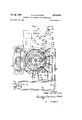
- FiG. l is a perspective view, partly in section, and
- FIG. 2 a central horizontal section with associated circuit and pipe diagrams.
- a heavy soft iron yoke l is provided with a magnetizing winding 2 and heavy pole shoes 3 and 4, the pole shoe No. 3 of which may be a north pole and No. 4 a south pole, as indicated.
- the inner electrode means is provided in the form of a single electrode constituted by a hollow metal tube 6- with a vertical axis placed centrally in the receptacle. its inner cavity '7 is included in an oil pipe circulation system described below.
- the outer electrode means comprises in this case a single primary outer electrode 8 being of a nearly annular form concentric to the electrode 6.
- Its inner operative surface is concave not only in a horizontal section but also in a vertical section as shown.
- an oil jacket 11 included in the oil circulation system.
- This primary outer electrode does not encircle the inner electrode 6 completely but is interrupted at the points 12 and 72.
- a secondary outer electrode 13 substantially conforming to the electrode 8 but having a considerable less peripheral extension so that gaps are formed between its extremes 14- and 15 and the points .12 and '72 respectively.
- this electrode is provided with an oil jacket 16 included in the oil circulation system.
- the second magnetizing means is constituted by two pairs of magnet coils T7, 18 and 19, 2%] respectively, provided inside the receptacle 5 and covered by protecting boxes, such as indicated at 21, preferably of heat proof material.
- Each pair of magnetic coils is arranged in an axial arrangement and the coils are dimensioned for producing a considerable number of ampere-turns.
- the pair 17, it of the second magnetizing means is placed adjacent the second outer electrode 13 whereas the other pair 19, 2d of the additional magnetizing means are provided peripherally displaced in relation thereto, e.g., diametrically opposed as indicated on the drawings.
- the oil pipe circulation system in cludes a main supply pipe 22, a pump 23 and a further pipe main 24 from which a number of branches 25, 26 and 2.7 are tapped off.
- a number of outgoing pipes 23, 29 and 39 are united to a comon return pipe 31.
- This pipe is connected to the input side of an heat exchanger 32, the output side of which is connected to pipe main 22.
- Each pipe has an electrically insulating tube section, such as indicated at 33, and the continuation of the pipe forms then an electrically insulated pipe section which may be associated with the corresponding electrode, while passing through insulating bushings, such as 49 and ii, at the inner electrode 6 and bushings, such as 42, at the outer electrodes.
- the insulated pipe section 34 is in communication with the top of the oil cavity 7 of the electrode 6 and the insulated pipe section 35 with the bottom of said cavity.
- the insulated pipe section 36 is in communication with the oil jacket 16 of the electrode 13 at the one end thereof whereas the insulated pipe section 37 is associated with the opposite end thereof.
- the insulated pipe 38 communicates with the oil jacket of the electrode 8 at the one end thereof Whereas the insulated pipe 39 communicates with the opposite end thereof.
- the low temperature side of the heat exchanger may have an intake 43 and an outtake 44 for the gas or fluid to be heated by the oil.
- the electric circuits of the system are as follows.
- the insulated pipe sections may conveniently serve as parts of the leads for connecting the electrodes to the outside of the receptacle.
- the pipe sections 34 and 35 are interconnected through a conductor 45 and, via the con- 'ductor 46, connected to the positive terminal of the rectifier 47.
- the pipes 38 and 39 associated with the main outer electrode 8 are interconnected through the conductor 48 and, via the conductor 49, connected to the negative side of the rectifier 47.
- the rectifier may be fed with high tension alternating voltage via a transformer 50 from an alternator 51.
- the field coil 2 is fed from a direct current source diagrammatically indicated as a battery 52. To this battery is connected a two pole double throw switch 53. In its one position it connects the negative pole via the conductor 54 and the branch wire 55 to the coil 18'and the positive pole via a conductor 57 and the branch wire 58 to the opposite terminal of the coil 18. At the same time the branch wires 56 and 59 connect the negative poles of the battery to the coil 17. The intensity of the local magnetic field produced between the coils will then be of the order of 10,000 to 100,000 gauss.
- the switch 53 in its opposite position will connect the two coils 19 and 20 into circuit via corresponding conductors indicated on the drawing.
- the switch 53 has a function to energize the two pairs of coils 19, 20, and 17, 18, respectively, in alternation.
- An evacuation pipe 60 is connected to the interior of the receptacle through an insulating bushing 61. This pipe is connected to a valve 61 and an evacuation pump 62.
- the system operates substantially as follows.
- a gas filling of the receptacle 5 of deuterium, D and/ or tritium, T is rarefied by means of the pump 62 to a pressure of to 10 torr.
- the coil 2 is energized so that there will be a practically uniform magnetic field in the gap between the pole shoes 3 and 4 passing through the receptacle 5.
- the intensity of this field should be in the order of 1,000 to 10,000 gauss.
- the pair of coils 17 and 18 will produce a local additional magnetic field also in substantially the same axial direction through the annular space formed between the inner and outer electrodes. This local field should be considerably stronger than the uniform field and the magnetic induction thereof should be at least ten times that of the uniform field.
- the pump 23 is put into operation whereby oil is forced to circulate through the cavities and jackets respectively of the electrodes 6, 8 and 13 and through the heat exchanger 32. Through the intake 43 and outtake 44 of the heat exchanger a fluid or liquid to be heated is caused to circulate in any conventional way. 7
- the rectifier 47 is then put into operation and delivers a voltage from 10 kv. up to 200 kv. and the gas filling is thereby ionized and a violet discharge is started between the inner and outer electrodes causing the formation of a hot circulating plasma as indicated at 63.
- the plasma will move perpendicular to the electric field between the electrodes 6 and 8 with a velocity of E/B in which E indicates the voltage and B the magnetic induction.
- the temperature of the plasma is very high and particularly that of its ions. This will 'be the case particularly if the degree of ionisation is high which is obtained by making the voltage between the inner and outer electrodes very high, such as from 20 kv. to 200 kv.
- the plasma is kept together as a rotating ring.
- this plasma ring meets the local magnetic field between coils 17 and 18 having an intensity of from 10,000 to 100,000 gauss, its temperature will be increased very considerably and reach such high values that thermo-nuclear reactions take place. Thereby the entire plasma will be further heated.
- thermo-nuclear development of energy will heat the electrodes and this heat is Withdrawn via the heat exchanger 32.
- the switch 53 If the switch 53 is switched over to its left hand position the pair of coils 19 and 20 will be energized and the coils 17 and 18 de-energized. This shifting of the coils is convenient because there will be an intense heating of them in view of the considerable energizing currents necessary to produce the high number of ampere turns. By switching over the energizing current from one coil pair to another the device may operate continuously.
- the number of pairs of coils may, of course, be more than two.
- An apparatus for producing gaseous plasma with extremely high temperature comprising a receptacle, the interior of which is isolated from the atmosphere, outer and inner electrode means insulated for high voltage and dimensioned for heavy currents and arranged in said receptacle, said outer electrode means surrounding said inner electrode means and being excited to a voltage opposite to that of said inner electrode means and providing between said outer and inner electrode means an annular discharge space, first magnetizing means for producing a substantially uniform magnetic field in an axial direction through said annular space, second magnetizing means for producing at least one local additional magnetic field in said annular space along an axis traversing said uniform magnetic field, said local magnetic field being of a several times higher intensity than said uniform field, evacuation means for rarefying gas included in said receptacle and ionisation means for initiating a discharge through said annular space.
- said outer electrode means is composed of at least one primary outer electrode and at least one secondary outer electrode, said secondary electrodes being electrically insulated from said primary electrodes and connected to exterior terminals separate therefrom.
Description
Jan. 22, 1963 H. o. G. ALFVEN 3,074,375
GENERATION 0F EXTREMELY HIGH TEMPERATURE Filed Sept. 29, 1959 2 sheets-sheet 1 Fig.1
/NVENTOR HANNES OLOF eiisTA ALFVEN his ATTORNEYS.
Jan. 22, 1963 H. o. G. ALFVEN 3,074,875
GENERATION OF EXTREMELY HIGH TEMPERATURE Filed Sept. 29, 1959 Y 2 Sheets-Sheet 2 Fig.2 gen [52 50 47' Rectifier 55 2F, ./55 I l 38 /IL/" I I a INVENTOR. I HANNES OLOF G'OSTA ALFVEN his A TTORNE YS.
3,h74,8?5 Patented Jan. 22, E963 tie GENEFATHR'BN F EXTREMELY HIGH TEMPERATURE Hermes Glof Giista Aii'vn, Emblaviigen 29, Diursholrn, Sweden Filed ept. 29, E59, Ser. No. 843,14 Claims priority, application Sweden Oct. 1, 1958 8 Qiairns. (Cl. eat-1912) The present invention has for its object to render possible the generation of extremely high temperatures, such as those required to initiate and maintain nuclear fusion reactions, e.g. with hydrogen isotopes, for research or other such purposes as are known to those skilled in the art of extremely high temperature plasmas. For different purposes, inter alia, in connection with thermonuclear reactors it is necessary to heat the gas concerned to such a high temperature, as a rule above 10 K., and to maintain it at such elevated temperature for a period of time of the order of size of one second.
It is known that such temperatures may be obtained by conducting a heavy electric current impulse through a rarefied gas confined in a straight or annular discharge tube having a diameter of about 1 meter.
One object of the invention is to produce a concentrated gas plasma having a longer life than the current impulse impressed. A further object is to obtain a higher temperature than has been hitherto possible and to establish the prerequisites for a technical utilisation of the heat developed at the high temperature through nuclear fusion.
To realize these objects and obtain other advantages the present invention is concerned with an apparatus comprising a receptacle, the interior of which is isolated from the atmosphere, outer and inner electrode means insulated for high voltage and dimensioned for heavy currents and arranged in said receptacle, said outer electrode means surrounding said inner electrode means and being excited to a voltage opposite to that of said inner electrode means and providing between said outer and inner electrode means an annular discharge space, first magnetizing means for producing a substantially uniform magnetic field in an axial direction through said annular space, second magnetizing means for producing at least one local additionm field also in substantially the same axial direction through said annular space and being of a several times higher intensity than said uniform field, evacuation means for rarefying gas included in said receptacle and ionisation means for initiating a discharge through said annular space. The ionisation means may principally consist of any known device able to ionize a gas. Thus the elecrodes may themselves be so shaped or connected to such a voltage source that the electric field between them produces, e.g., a corona discharge which ionizes the gas. It may be found suitable to provide a special electric are or glow discharge device, such as a heated cathode or a so called electrode gun, in the discharge space. In the present instance it has been found satisfactory to include in said means a high voltage source, any further specific means for this purpose being, in fact, not necessary, it being understood that a powerful electric direct current producer, such as a rectifier, will have to deliver a voltage of from kv. up to 200 kv. to produce an instantaneous discharge current of the order of 10 amperes through a gas filling of deuterium, D and/ or tritium, T rarefied to a pressure of 10' to 10* torr. The output of such a rectifier will thus serve the twofold purpose of ionizing the gas in the receptacle and delivering the subsequent heavy discharge current.
Said outer electrode means may be composed of at least one primary outer electrode and at least one secondary outer electrode, said secondary electrodes being electricaily insulated from said primary electrodes and connected to exterior terminals separate therefrom.
The invention will now be more specifically described with reference to the accompanying drawings on which FiG. l is a perspective view, partly in section, and
FIG. 2 a central horizontal section with associated circuit and pipe diagrams.
In the drawings a heavy soft iron yoke l is provided with a magnetizing winding 2 and heavy pole shoes 3 and 4, the pole shoe No. 3 of which may be a north pole and No. 4 a south pole, as indicated. In the gap between said pole shoes there is inserted a cylindrical airtight receptacle 5 of a non-magnetic substance, such as copper. The inner electrode means is provided in the form of a single electrode constituted by a hollow metal tube 6- with a vertical axis placed centrally in the receptacle. its inner cavity '7 is included in an oil pipe circulation system described below. The outer electrode means comprises in this case a single primary outer electrode 8 being of a nearly annular form concentric to the electrode 6. Its inner operative surface is concave not only in a horizontal section but also in a vertical section as shown. Between an inner Wall 9 and an outer wall 10 there is provided an oil jacket 11 included in the oil circulation system. This primary outer electrode does not encircle the inner electrode 6 completely but is interrupted at the points 12 and 72. In the interspace between said points there is provided a secondary outer electrode 13 substantially conforming to the electrode 8 but having a considerable less peripheral extension so that gaps are formed between its extremes 14- and 15 and the points .12 and '72 respectively. Also this electrode is provided with an oil jacket 16 included in the oil circulation system.
In this embodiment the second magnetizing means is constituted by two pairs of magnet coils T7, 18 and 19, 2%] respectively, provided inside the receptacle 5 and covered by protecting boxes, such as indicated at 21, preferably of heat proof material. Each pair of magnetic coils is arranged in an axial arrangement and the coils are dimensioned for producing a considerable number of ampere-turns. The pair 17, it of the second magnetizing means is placed adjacent the second outer electrode 13 whereas the other pair 19, 2d of the additional magnetizing means are provided peripherally displaced in relation thereto, e.g., diametrically opposed as indicated on the drawings.
As seen from FIG. 2 the oil pipe circulation system in cludes a main supply pipe 22, a pump 23 and a further pipe main 24 from which a number of branches 25, 26 and 2.7 are tapped off. A number of outgoing pipes 23, 29 and 39 are united to a comon return pipe 31. This pipe is connected to the input side of an heat exchanger 32, the output side of which is connected to pipe main 22. Each pipe has an electrically insulating tube section, such as indicated at 33, and the continuation of the pipe forms then an electrically insulated pipe section which may be associated with the corresponding electrode, while passing through insulating bushings, such as 49 and ii, at the inner electrode 6 and bushings, such as 42, at the outer electrodes. Thus, the insulated pipe section 34 is in communication with the top of the oil cavity 7 of the electrode 6 and the insulated pipe section 35 with the bottom of said cavity. The insulated pipe section 36 is in communication with the oil jacket 16 of the electrode 13 at the one end thereof whereas the insulated pipe section 37 is associated with the opposite end thereof. The insulated pipe 38 communicates with the oil jacket of the electrode 8 at the one end thereof Whereas the insulated pipe 39 communicates with the opposite end thereof.
The low temperature side of the heat exchanger may have an intake 43 and an outtake 44 for the gas or fluid to be heated by the oil.
The electric circuits of the system are as follows. The insulated pipe sections may conveniently serve as parts of the leads for connecting the electrodes to the outside of the receptacle. Thus, the pipe sections 34 and 35 are interconnected through a conductor 45 and, via the con- 'ductor 46, connected to the positive terminal of the rectifier 47. The pipes 38 and 39 associated with the main outer electrode 8, are interconnected through the conductor 48 and, via the conductor 49, connected to the negative side of the rectifier 47. .The rectifier may be fed with high tension alternating voltage via a transformer 50 from an alternator 51.
The field coil 2 is fed from a direct current source diagrammatically indicated as a battery 52. To this battery is connected a two pole double throw switch 53. In its one position it connects the negative pole via the conductor 54 and the branch wire 55 to the coil 18'and the positive pole via a conductor 57 and the branch wire 58 to the opposite terminal of the coil 18. At the same time the branch wires 56 and 59 connect the negative poles of the battery to the coil 17. The intensity of the local magnetic field produced between the coils will then be of the order of 10,000 to 100,000 gauss.
It is evident that in a similar way the switch 53 in its opposite position will connect the two coils 19 and 20 into circuit via corresponding conductors indicated on the drawing. The switch 53 has a function to energize the two pairs of coils 19, 20, and 17, 18, respectively, in alternation.
An evacuation pipe 60 is connected to the interior of the receptacle through an insulating bushing 61. This pipe is connected to a valve 61 and an evacuation pump 62.
The system operates substantially as follows. A gas filling of the receptacle 5 of deuterium, D and/ or tritium, T is rarefied by means of the pump 62 to a pressure of to 10 torr. The coil 2 is energized so that there will be a practically uniform magnetic field in the gap between the pole shoes 3 and 4 passing through the receptacle 5. The intensity of this field should be in the order of 1,000 to 10,000 gauss. In the right hand position of the switch 53 the pair of coils 17 and 18 will produce a local additional magnetic field also in substantially the same axial direction through the annular space formed between the inner and outer electrodes. This local field should be considerably stronger than the uniform field and the magnetic induction thereof should be at least ten times that of the uniform field. This local field will, however, not be as uniform as the field between the shoes 3 and 4, it being understood that the magnetic induction will be considerably higher close to the coils than in the central space between the coils. The pump 23 is put into operation whereby oil is forced to circulate through the cavities and jackets respectively of the electrodes 6, 8 and 13 and through the heat exchanger 32. Through the intake 43 and outtake 44 of the heat exchanger a fluid or liquid to be heated is caused to circulate in any conventional way. 7
The rectifier 47 is then put into operation and delivers a voltage from 10 kv. up to 200 kv. and the gas filling is thereby ionized and a violet discharge is started between the inner and outer electrodes causing the formation of a hot circulating plasma as indicated at 63. The plasma will move perpendicular to the electric field between the electrodes 6 and 8 with a velocity of E/B in which E indicates the voltage and B the magnetic induction. The temperature of the plasma is very high and particularly that of its ions. This will 'be the case particularly if the degree of ionisation is high which is obtained by making the voltage between the inner and outer electrodes very high, such as from 20 kv. to 200 kv. Through the so called pinch effect the plasma is kept together as a rotating ring. When this plasma ring meets the local magnetic field between coils 17 and 18 having an intensity of from 10,000 to 100,000 gauss, its temperature will be increased very considerably and reach such high values that thermo-nuclear reactions take place. Thereby the entire plasma will be further heated.
The thermo-nuclear development of energy will heat the electrodes and this heat is Withdrawn via the heat exchanger 32.
If the switch 53 is switched over to its left hand position the pair of coils 19 and 20 will be energized and the coils 17 and 18 de-energized. This shifting of the coils is convenient because there will be an intense heating of them in view of the considerable energizing currents necessary to produce the high number of ampere turns. By switching over the energizing current from one coil pair to another the device may operate continuously. The number of pairs of coils may, of course, be more than two.
border to obtain a maximum heating of the plasma it is necessary that this does not contain impurities of heavy elements. As the heavier ions are moving in larger trochoidal paths they will more easily reach the negative electrode which may be adapted to absorb and remove the impurities.
When the movement of the plasma is braked by the intense magnetic field from one of the coils 17, 18 or 19, 20, respectively, the electric field will be intensified due to space charges caused by the inertia effect. The electrode 13 close to the local magnetic field between coils 17 and 18 will then be charged to a higher negative voltage than the main electrode 8 surrounding the weaker uniform field. This renders it possible to take out electric energy at a higher voltage between the terminal 64 and the conductor 46 than between the conductors 49 and '46, the terminal 64 being connected via conductors 65 and 66 and pipes 36 and 37 to the electrode 13.
For similar reasons it may be found of advantage to provide more than one local electrode 13, as indicated at 67 with dashed and dotted lines in which case there will be two main electrodes 68 and 69 separated therefrom by gaps 70 and 71. The necessary oil pipes will then have to be attached according to the same principle as that laid down in connection with the embodiment of FIG. 2 shown in full lines.
What is claimed is:
1. An apparatus for producing gaseous plasma with extremely high temperature and comprising a receptacle, the interior of which is isolated from the atmosphere, outer and inner electrode means insulated for high voltage and dimensioned for heavy currents and arranged in said receptacle, said outer electrode means surrounding said inner electrode means and being excited to a voltage opposite to that of said inner electrode means and providing between said outer and inner electrode means an annular discharge space, first magnetizing means for producing a substantially uniform magnetic field in an axial direction through said annular space, second magnetizing means for producing at least one local additional magnetic field in said annular space along an axis traversing said uniform magnetic field, said local magnetic field being of a several times higher intensity than said uniform field, evacuation means for rarefying gas included in said receptacle and ionisation means for initiating a discharge through said annular space.
2. The apparatus of claim 1 in which said ionisation means include a high voltage source connected across said outer and inner electrode means.
3. The apparatus of claim 1 in which said outer electrode means is composed of at least one primary outer electrode and at least one secondary outer electrode, said secondary electrodes being electrically insulated from said primary electrodes and connected to exterior terminals separate therefrom.
4. The apparatus of claim 1 in which at least two second magnetizing means are provided for producing at least two local additional magnetic fields peripherally spaced in the annular discharge space, and switch means are provided to energize said coils sequentially.
5. The apparatus of claim 3 in which said secondary outer electrode is provided adjacent to one of said second magnetizing means.
6. The apparatus of claim 1 in which said second magnetizing means are of a suflicient strength to produce a local additiona1 magnetic field of an intensity at least ten times that of said substantially uniform field.
7. The apparatus of claim 1 in which said electrodes means are provided with cooling means for withdrawing heat energy from the electrodes.
8. The apparatus of claim 1 in which said second magnetizing means is accentrically disposed relative to said first magnetizing means.
References Sited in the file of this patent UNITED STATES PATENTS 2,162,807 Fritz June 20, 1939 6 2,213,543 Brett Sept. 3, 1940 2,928,992 Alfven et al Mar. 15, 1960 2,971,122 Sloan Feb. 7, 1961 FOREIGN PATENTS 1,171,808 France Oct. 6, 1958 1,174,435 France Nov. 3, 1958 OTHER REFERENCES Proceedings of the Second United Nations International Conference on the Peaceful Uses of Atomic Energy, vol. 32, United Nations, Geneva, 1958; held in Geneva Sept. 1-13, 1958, pages 126, 127, 155-160.
Project Sherwood, by Amasa S. Bishop; Addison Wesley Publishing Co., Inc, Reading, Mass, September 1958, pages 127-131.
Claims (1)
1. AN APPARATUS FOR PRODUCING GASEOUS PLASMA WITH EXTREMELY HIGH TEMPERATURE AND COMPRISING A RECEPTACLE, THE INTERIOR OF WHICH IS ISOLATED FROM THE ATMOSPHERE, OUTER AND INNER ELECTRODE MEASNINSULTED FOR HIGH VOLTAGE AND DIMENSIONED FOR HEAVY CURRENTS AND ARRANGED IN SAID RECEPTACLE SAID OUTER ELECTRODE MEANS SURROUNDING SAID INNER ELETRODE MEANS AND BEING EXCITED TO A VOLTAGE OPPOSITE TO THAT OF SAID INNER ELECTRODE MEANS AND PROVIDING BETWEEN SAID OUTER AND INNER ELECTRODE MEANS AN ENNULAR DISCHARGE SPACE, FIRST MAGNETIZING MEANS FOR PRODUCING A SUBSTANTIALLY UNIFORM MAGNETIC FIELD IN AN AXIAL DIRECTION THROUGH SAID ANNULAR SPACE, SECOND MAGNETIZING MEANS FOR PRODUCING AT LEAST ONE LOCAL ADDITIONAL MAGNETIC FIELD IN SAID ANNULAR SPACE ALONG AN AXIS TRAVERSING SAID UNIFORM MAGNETIC FIELD, SAID LOCAL MAGNETIC FIELD BEING OF A SEVERAL TIMES HIGHER IN7TENSITY THAN SAID UNIFORM FIELD, EVACUATION MEANS FOR RAREFYING GAS INCLUDED IN SAID RECEPTACLE AND INOISATION MEANS FOR INITIATING A DISCHARGE THROUGH SAID ANNULAR SPACE
Applications Claiming Priority (1)
| Application Number | Priority Date | Filing Date | Title |
|---|---|---|---|
| SE3074875X | 1958-10-01 |
Publications (1)
| Publication Number | Publication Date |
|---|---|
| US3074875A true US3074875A (en) | 1963-01-22 |
Family
ID=20428437
Family Applications (1)
| Application Number | Title | Priority Date | Filing Date |
|---|---|---|---|
| US843194A Expired - Lifetime US3074875A (en) | 1958-10-01 | 1959-09-29 | Generation of extremely high temperature |
Country Status (1)
| Country | Link |
|---|---|
| US (1) | US3074875A (en) |
Cited By (1)
| Publication number | Priority date | Publication date | Assignee | Title |
|---|---|---|---|---|
| US3189523A (en) * | 1961-03-27 | 1965-06-15 | Avco Corp | Means for producing high temperature plasma |
Citations (6)
| Publication number | Priority date | Publication date | Assignee | Title |
|---|---|---|---|---|
| US2162807A (en) * | 1936-08-17 | 1939-06-20 | Telefunken Gmbh | Magnetron |
| US2213543A (en) * | 1937-08-07 | 1940-09-03 | Rca Corp | Electron discharge device |
| FR1171808A (en) * | 1957-04-19 | 1959-01-30 | Vickers Electrical Co Ltd | Improvements relating to the production of energy by nuclear reactions |
| FR1174435A (en) * | 1957-05-02 | 1959-03-11 | British Thomson Houston Co Ltd | Improvements to nuclear reactors |
| US2928992A (en) * | 1951-06-30 | 1960-03-15 | Ericsson Telefon Ab L M | Electron tubes of the multi reflexion type |
| US2971122A (en) * | 1958-06-23 | 1961-02-07 | Univ California | High-power magnetron |
-
1959
- 1959-09-29 US US843194A patent/US3074875A/en not_active Expired - Lifetime
Patent Citations (6)
| Publication number | Priority date | Publication date | Assignee | Title |
|---|---|---|---|---|
| US2162807A (en) * | 1936-08-17 | 1939-06-20 | Telefunken Gmbh | Magnetron |
| US2213543A (en) * | 1937-08-07 | 1940-09-03 | Rca Corp | Electron discharge device |
| US2928992A (en) * | 1951-06-30 | 1960-03-15 | Ericsson Telefon Ab L M | Electron tubes of the multi reflexion type |
| FR1171808A (en) * | 1957-04-19 | 1959-01-30 | Vickers Electrical Co Ltd | Improvements relating to the production of energy by nuclear reactions |
| FR1174435A (en) * | 1957-05-02 | 1959-03-11 | British Thomson Houston Co Ltd | Improvements to nuclear reactors |
| US2971122A (en) * | 1958-06-23 | 1961-02-07 | Univ California | High-power magnetron |
Cited By (1)
| Publication number | Priority date | Publication date | Assignee | Title |
|---|---|---|---|---|
| US3189523A (en) * | 1961-03-27 | 1965-06-15 | Avco Corp | Means for producing high temperature plasma |
Similar Documents
| Publication | Publication Date | Title |
|---|---|---|
| US4233537A (en) | Multicusp plasma containment apparatus | |
| US2991238A (en) | Pinched plasma reactor | |
| US2997436A (en) | Gas ionizing and compressing device | |
| GB859459A (en) | Apparatus and method for confining a plasma | |
| US3059149A (en) | Plasma accelerator | |
| US2480169A (en) | Apparatus for imparting high energy to charged particles | |
| US4661710A (en) | Negative ion source | |
| US3445722A (en) | Plasma manipulation method and apparatus | |
| US3692626A (en) | Apparatus for forming and containing plasma | |
| GB1101293A (en) | High output duoplasmatron-type ion source | |
| US3074875A (en) | Generation of extremely high temperature | |
| US3801438A (en) | Toroidal apparatus for confining plasma | |
| GB1077516A (en) | The generation and/or acceleration of plasma | |
| US3467885A (en) | Method and apparatus for electromagnetically containing a plasma | |
| US3107211A (en) | Nuclear apparatus | |
| US2961557A (en) | Apparatus for creating by induction an electric discharge in a gas at low pressure | |
| US3183403A (en) | Magneto hydrodynamic fluid accelerator and compressor | |
| US3302095A (en) | Direct current to alternating current converter | |
| US3229155A (en) | Electric arc device for heating gases | |
| US3660700A (en) | Magnetohydrodynamic generator | |
| US2247745A (en) | Magnetizer | |
| US3361634A (en) | Plasma method and apparatus for generating energy | |
| KR102154630B1 (en) | Hybrid electric boiler apparatus and the boiling apparatus adapted to the boiler apparatus | |
| US3031396A (en) | Stabilized pinch machine | |
| US3614638A (en) | Betatron |