US3055170A - Liquid thermal engine - Google Patents
Liquid thermal engine Download PDFInfo
- Publication number
- US3055170A US3055170A US728307A US72830758A US3055170A US 3055170 A US3055170 A US 3055170A US 728307 A US728307 A US 728307A US 72830758 A US72830758 A US 72830758A US 3055170 A US3055170 A US 3055170A
- Authority
- US
- United States
- Prior art keywords
- liquid
- heater
- stroke
- cylinder
- engine
- Prior art date
- Legal status (The legal status is an assumption and is not a legal conclusion. Google has not performed a legal analysis and makes no representation as to the accuracy of the status listed.)
- Expired - Lifetime
Links
Images


Classifications
-
- F—MECHANICAL ENGINEERING; LIGHTING; HEATING; WEAPONS; BLASTING
- F01—MACHINES OR ENGINES IN GENERAL; ENGINE PLANTS IN GENERAL; STEAM ENGINES
- F01B—MACHINES OR ENGINES, IN GENERAL OR OF POSITIVE-DISPLACEMENT TYPE, e.g. STEAM ENGINES
- F01B15/00—Reciprocating-piston machines or engines with movable cylinders other than provided for in group F01B13/00
- F01B15/04—Reciprocating-piston machines or engines with movable cylinders other than provided for in group F01B13/00 with oscillating cylinder
-
- F—MECHANICAL ENGINEERING; LIGHTING; HEATING; WEAPONS; BLASTING
- F03—MACHINES OR ENGINES FOR LIQUIDS; WIND, SPRING, OR WEIGHT MOTORS; PRODUCING MECHANICAL POWER OR A REACTIVE PROPULSIVE THRUST, NOT OTHERWISE PROVIDED FOR
- F03G—SPRING, WEIGHT, INERTIA OR LIKE MOTORS; MECHANICAL-POWER PRODUCING DEVICES OR MECHANISMS, NOT OTHERWISE PROVIDED FOR OR USING ENERGY SOURCES NOT OTHERWISE PROVIDED FOR
- F03G7/00—Mechanical-power-producing mechanisms, not otherwise provided for or using energy sources not otherwise provided for
- F03G7/06—Mechanical-power-producing mechanisms, not otherwise provided for or using energy sources not otherwise provided for using expansion or contraction of bodies due to heating, cooling, moistening, drying or the like
Definitions
- This invention relates to engines and more particularly to a new engine which is operated by expansion of iluid maintained in the liquid state throughout the operation of the engine.
- An engine according to this invention utilizes Huid in the liquid state at relatively high pressures. Since liquids are not easily compressed, small increases in ternperature develop very large pressures which are utilized to operate the engine even at low temperature diiferentials. Also, since the pressure level of the engine is very high when compared with gas engines above referred to, a small structure can be used to produce large amounts of power. In addition, according to this invention, high torques are produced so a given horsepower is produced even at low speeds.
- FIGIRE l is a view of a one cylinder engine system with portions thereof shown as cross section;
- FIGURE 2 is a plan view partially in sections showing the structural details of the engine drive mechanism
- FIGURE 3 is a side elevation partially in longitudinal section taken along 3 3 of FIGURE 2;
- FIGURE 3a is an enlarged fragmentary section of the valve mechanism
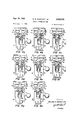
- FIGURES 4a through 4h are schematic illustrations of the one cylinder liquid engine showing the operating conditions through an entire cycle of operation
- FIGURE 5 is a schematic view of a multi-cylinder engine, according to this invention, with parts removed for purposes of clarity;
- FIGURES 6a through 6h are schematic views of the 3,055,170 Patented Sept. 25, 1962 ICC engine shown in FIGURE 5 showing the sequence of operation through one full cycle;
- FIGURE 7 is a pressure-stroke diagram of the cycle of operation
- FIGURES 8a and 8b lare enlarged fragmentary sections of the two cams used to operate the valves of the engine shown in FIGURES l to 4;
- FIGURE 8c is a pictorial representation of the valve operation of the engine shown in FIGURES 1 through 4.
- a liquid cycle is utilized in which heated, compressed liquid is expanded against a working surface to produce mechanical power.
- This expansion of the liquid reduces the pressure of the liquid, converting heat energy into mechanical work, and is referred to herein as elastic expansion, as distinguished from thermal expansion.
- the cycle comprises the steps of mechanically compressing the liquid, adding heat to the liquid while it is compressed and expanding the liquid against a working surface to convert at least a portion of the heat energy of the liquid to mechanical power.
- the compression takes place in a relatively short period of time after which the heat energy is added to the liquid to elevate its temperature and pressure for a relatively long period of time.
- the steps of the cycle performed by the illustrated engine are substantially sequential, the heating and expanding of the liquid may be partially or entirely simultaneous.
- the temperature of the liquid may increase due to the addition of heat, may decrease due to the removal of work energy therefrom, or may remain constant.
- a closed cycle engine is used wherein the liquid is cooled after it has performed the work so that cool liquid is compressed prior to heating.
- the liquid may not be cooled and new cool liquid may be supplied from a separate source.
- the temperature of the heat source is maintained above the temperature of the mechanically compressed liquid so that the liquid can be further heated.
- FIGURES l through 4 illustrate a one cylinder engine, according to this invention, with its associated heater and cooling heat exchanger.
- the engine l0 is connected to the cool or outlet side of a heat exchanger 11 by a line 12 and to the hot or inlet side of the heat exchanger 11 through a line 13.
- cool liquid is supplied to the engine through the line I2.
- the cool liquid After the cool liquid enters the engine 10, it is compressed and alternately pumped through high pressure lines I4 and 16 to heater units I7 and 18 respectively.
- the liquid After the liquid is heated within the heater units I7 and 18, as will be described below, it returns to the engine 10 at a higher pressure and is expanded against a piston to produce work. After the liquid has produced the mechanical work, it is cooled.
- an accumulator 19 is connected to one or the other of the lines 12 or I3 to prevent an undesirable buildup of pressure within the cooling circuit to supply make-up liquid to replace leakage and to maintain a predetermined supply pressure on the circuit. As shown, it is connected to the line 13.
- the engine 10 includes Ia housing assembly 21 in which is journalled a crankshaft 22. Also mounted in the housing assembly 21 is a cylinder pivot pin 23 which projects through a bore 24 formed in a cylinder head 26. A pair of opposed bushings 27 rand 28 support the cylinder pivot pin 23 within the housing assembly 21 and also provide opposed radial walls which eng-age opposite sides of the cylinder head 26 and .prevent axial movement thereof along the cylinder pivot pin 23.
- the cylinder head 26 is supported in the housing assembly 21 against motion, excepting rotary motion in a plane perpendicular to the axis of the cylinder pivot pin 23 as shown lby the phantom positions of FIG- URE 3.
- a piston 29 extends into a cylinder bore 31 formed in the cylinder head 26 and is axially movable relative thereto. Seals 35 are mounted on the piston 29 and provide a sealing engagement between the piston 29 and the cylinder bore 31 so that axial movement of the piston 29 causes a change in displacement of the chamber 30 above the piston 29 within the cylinder head 26.
- the right hand end of the piston 29 is ⁇ formed with a journal bearing 32 connected to yan eccentric bearing 33 on the crankshaft 22.
- the piston 29 reciprocates or strokes in and out of the cylinder head 26.
- I utilize the pivotal connection of the cylinder head 26 on the cylinder pivot pin 23 as described above.
- the cylinder head 26 oscillates around the cylinder pivot pin 23 when the crankshaft 22 rotates.
- the cylinder pivot pin 23 is formed with a radial passage 34 which is open to an axial passage 36 formed in the cylinder head 26.
- the radial passage 34 in turn connects with an axial passage 37 inthe cylinder pivot pin 23 so that uid communication is provided between the end surface 38 of the cylinder pivot pin 23 and the cylinder bore 31 above the piston 29.
- the radial passage 34 should be enlarged, as shown in FIGURE 3, -at its outer end so that it maintains communication with the passage 36 in all positions of the cylinder head 26 and, in effect, provides a swivel connection.
- a valve block 39 is mounted in the housing assembly 21 by bolt fasteners 41 and is provided with a side face 42 positioned against the end surface 38 of the cylinder pivot pin 23.
- a passage 43 is formed in the valve block 39 and communicates with the axial passage 37.
- the valve ⁇ block 39 is Aalso formed with a first valve bore 44 and a second valve bore 46 in which are positioned spool valves 47 and 48 respectively.
- An annular groove 49 within the bore 44 in the valve block 39 communicates with the passage ⁇ 43 on one side and a second passage 51 which in turn communicates with an annular groove S2 within the bore 46.
- the cylinder bore 31 is always in communication with the two annular grooves 49 and 52 through the passages 34, 36, 37, 43, and 51.
- the spool valve 47 is formed with a central land 53 adapted to close the annular groove 49 when the valve is in the olf position and the spool 48 is formed with a central land 54 adapted to close the annular groove 52 when the spool 48 is in i-ts off position. It should be noted that, in FIGURE 3a, the spool valve 48 has been displaced from the off position but that the central land 54 is movable to cover the annular groove S2 and isolate the lines 12 and 13 from the rest of the system.
- a pair of ports 56 and 57 connect with the valve bore 44 on either side of the annular groove 49 and in turn to the pressure lines 14 and 16 shown in FIGURES 1 and 2.
- the port 57 is connected to the annular groove 49 so the pressure line 16 is connected to the cylinder bore 31.
- the port 56 and in turn the pressure line 14 is connected to the cylinder bore 31.
- Two addi-tional por-ts S and 59 are formed in the valve block 39 and communicate with the second valve bore 46 on either side of the annular groove 52 and connect to the lines 12 and 13 respectively.
- valve spool 48 when the valve spool 48 is in the position shown in FIGURE 3a, the linew 13 is in communication with the cylinder bore 31.V
- the valve spool 4S moves to the position wherein the central land 54 covers the ⁇ annular groove 52, both of the lines 12 and 13 are isolated from the cylinder bore 4 31 and further movement to the right brings the line 12 into communication with the. cylinder .bore 31. Therefore, the valve spools 47 and 48 can be selectively operated to provide communication between the cylinder bore 31 and any of the lines 12, 13, 14, or 16.
- timing gear 61 which interrneshes with a second timing gear 62 mounted on a cam shaft 63 jou-mailed in the housing assembly 21.
- the cam shaft 63 is rotated with a fixed ratio of relative velocities.
- the timing gears 61 and 62 are sized so that the cam shaft rotates one revolution every time the crankshaft 22 trotates through four revolutions so the timing gears provide a 4:1 gear reduction.
- a n ⁇ rst cam 64 is mounted on the cam shaft 63 and is arranged to engage a cam follower 66 on the rst valve spool 47.
- a spring 67 is positioned against the outer end of the spool 47 by a cap 68 threaded into the end of the housing assembly 21 to resiliently maintain the cam follower 66 in engagement with the cam 64.
- a second cam 69 is mounted on the cam shaft 63 and is engaged by a cam ⁇ follower 71 mounted on the end of the second valve 4S.
- a spring 72 is held ⁇ against the second valve spool 48 by a cap 73 so the cam follower 71 is resiliently maintained in engagement with the cam 69.
- FIGURE l one form of heater structure is shown in the longitudinal section of the heater 18.
- the pressure line 16 connects to the upper end of the heater 18 through a port 77.
- the port 77 communicates with an annular chamber 78 dened by a central tubular member 79 and an outer housing 81.
- the annular chamber 78 has a relatively small radial width but a very large area when considering the volume so that heat will flow through both the inner wall of the tubular member 79 and the outer housing 81 bordering the annular chamber 78. Rapid heat transfer is achieved with relatively low temperature differentials because of this large area compared to a relatively small mass of liquid being heated.
- the lower end of the outer housing 81 is formed with an enlarged portion 82 which has a substantially larger volume than the volume of the annular chamber 7S.
- the tubular member 79 and the housing are sealed at their ends by welds.
- the heater is lled with liquid even when it is not compressed.
- additional liquid is pumped into the heater 1S through the pressure line 16
- it compresses the original liquid by displacing the original liquid down along the annular chamber 78.
- the various proportions are preferably arranged so the voltune of the annular chamber 78 is at least equal to the compressed volume of liquid pumped into the heater 18 during the compression stroke. In effect, the original liquid contained Within the heater 18 is compressed into the enlarged portion 82 and operates as a liquid spring.
- the cool liquid contained within the annular chamber 78 is then heated. This elevates the temperature and the pressure of the liquid contained Within the heater 18 until the heater is again connected to the cylinder bore 31.
- the heated liquid within the chamber 78 is then caused to flow back through the pressure line 16 into the cylinder bore by expansion of the compressed liquid, including that originally contained within the heater and located within the enlarged portion during the heating phase.
- hot liquid 74 within a heater container 76 is used as the source of heat for the heaters 17 and 18 but any suitable source of heat such as hot gases, flames, or other available forms of heat can be used to supply heat to the heaters 17 and 18.
- the piston 29 operates on a four-stroke cycle including the usual intake, compression, power, and exhaust strokes
- the heaters 17 and 18 operate through a cycle which requires four complete revolutions of the crankshaft 22, and it is for this reason that a four to one gear reduction is used in driving the cam shaft 63 to provide proper synchronism of the engine at all times.
- valve spool 47 and 48 operate to change the flow in two uid lines
- the valve spool 47 is indicated by two schematic valves indicated as short dashes 47a and 47b which are in the lines 14 and 16 respectively.
- the Valve spool 48 is similarly indicated at 48a and 48h in the lines 12 and 13 respectively. These schematic valves cross the associated lines when the valves are closed and are aligned with the lines when the valves are open for liquid ow.
- the heaters In order to indicate the condition of the liquid and the various portions of the system, I have indicated in the heaters the phase through which the liquid is passing. As an example, comp is indicated in the heater which is being compressed, heating indicates that the liquid -is in the process of being heated and is isolated from the rest of the system, heated indicates that the liquid has been heated and is connected to the cylinder to provide a power stroke, and static indicates that the liquid originally within the heater is at low pressure. It should be understood that the liquid within the lines 12 and 13 and within the cooling heat exchanger 11 is at a low pressure determined by the accumulator 19.
- the piston 29 is moving downwardly relative to the cylinder head 26 as indicated by the arrow on the piston 29.
- the piston is on an intake stroke and cool liquid under low pressure passes from the heat exchanger 11 through the line 12 into the chamber 30 in the cylinder head 26.
- the valve 48a is in a position to provide uid communication between the chamber 30 and the line 12, and the exhaust valve 4812 isolates the line 13 from the chamber 30.
- the valve spool 47 is shown schematically at 47a and 47b and is in the oif position so that the two heaters 17 and 18 are isolated from the chamber 30. Therefore, as the piston 29 moves down, cool liquid flows from the heat exchanger into the chamber 30. Because of this flow out of the low pressure side of the system, the accumulator 19 supplies liquid to the line 13.
- the chamber 30 above the piston contains cool liquid about to be compressed during the next stroke of the piston.
- the valve positions are changed by the cams shown in FIGURES 2, 8a and 8b to establish lfluid communication between the heater 18 and the chamber 30 through the valve 47b and all of the other valves are closed.
- the liquid is compressed in the heater 18 to a relatively high pressure which is determined by the compression ratio and the particular liquid.
- hydraulic fluid identified by the military speciiication No. MIL-O-5606 entitled Oil, Hydraulic, Aircraft, Petroleum Base approved January 31, 1950, by the U.S.
- the piston starts the second half of the cycle. Intake is effected by the outward stroke of the piston 29 to draw in cool liquid from the line 12.. During this stroke, the valve 48a is again opened and the other valves closed by the cams. This stroke corresponds to the stroke of FIGURE 4a in that it is also an intake stroke. However, at this time, the heater 17 is under low pressure andthe heater 18 under high pressure which is the reverse of the conditions present in FIGURE 4a. After the intake stroke of FIGURE 4e, the Valve 47a is opened by the cams while the other valves are closed so that when the piston 29 moves in, it compresses the liquid into the heater 17 as shown in FIGURE 4f.
- valve 47 b is opened and the other Valves are closed by the cams, thereby subjecting the piston 29 to the compressed and heated liquid with the heater 18 to effect the outward or power stroke of the piston as shown in FIGURE 4g.
- the valve 48h is held open and the other valves closed by the cams, and the piston 29 moves inwardly to elfect the last exhaust stroke of the cycle.
- the exhaust liquid is pumped out of the chamber 30 into the line 13 at low pressure and is stored in the accumulator -19 as shown in FIGURE 4h.
- the next stroke is a repetition of the stroke shown in FIGURE 4a. Therefore, the engine has a complete cycle every eight strokes or four revolutions.
- the heater 18 is being charged or pressurized in the FIGURE 4b and remains under pressure yfor heating until the power stroke of FIGURE 4g. If the compression is only assumed to be present from the mid-position of the compression stroke of FIGURE 4b to the mid-position of it is apparent that the liquid contained in the heater 18 is being heated through 900 of crankshaft rotation, thereby providing suicient time for the liquid contained within the heater to absorb enough additional heat to provide mechanical power.
- the heating cycle is equal to 180 plus 6o the number of heaters minus one heater times 720.
- the heating cycle of a given heater extends for 900 of crankshaft rotation. If three heaters are used, the heating cycle for a given heater extends through 1620 o-f crankshaft rotation and if four heaters are used, the heating cycle for a given heater extends through 2340 tion.
- the liquid contained within the heater 18 is at a pressure substantially equal to the pressure maintained in the cooling circuit by the accumulator 19, as hereinafter explained.- Therefore, this liquid is Ymerely compressed and expanded during each stroke.
- This liquid retained in the heater serves as a liquid spring compressed by the working liquid from the chamber 30.
- the resulting mixture of liquid would be at a temperature approaching the temperature of the hot liquid 74 and there would be a smaller temperature differential to cause the heat energy to ow into the working or compressed liquid.
- a larger temperature differential is present between the hot liquid 74 and the cool working or compressed liquid pumped into the heater when mixing does not take place, and since the heat ow through agiven wall is a I:function of the temperature difference,4 a greater amount of heat energy flows into the working liquid producing more power.
- the liquid originally contained within the heater and more particularly within the enlarged portion 82 thereto functions as a liquid spring and enables the pumping of cool working liquid 4from the cylinder 26 int-o the annular chamber 78 of the heater. It will be understood that other types of springs could be substituted for the liquid contained within -the heater.
- ⁇ It is preferred to provide short pressure lines 14 and 16 and locate the heaters as close to the engine 16 as possible.
- the pressure lines are of relatively small cross sectionV since small volumesof liquid ow through the engine system even 4for high horsepower outputs. In this way, substantially all the liquid is displaced from the cylinder to the heater With a minimum amount of liquid remaining within the connecting system, which has a volurne substantially less than the displacement volume of y the cylinder.
- the various proportions have been exaggerated for purposes of illustration.
- the heat exchanger 11 and the accumulator 19 are substantially larger than illustrated.
- FIGURE 7 the pressure-stroke cycle of the engine 10 is illustrated. It is recognized that in actual operation heat transfer is not conned to only the portion 0f the stroke wherein the liquid is isolated within the heater, but since the power stroke and the compression stroke are of short duration when compared to the period of time the liquid remains compressed within the heater, most of the heat is transferred to the compressed liquid during the period wherein the heater containing the compressed liquid is closed or isolated from the system.
- the compression stroke is represented by the curve connecting thepoints 83 and 84 which is assumed to be an adiabatic compression which takes place during the compression stroke.
- the liquid within the heater 4 is then heated at constant volume from the point 84 to the point 86.
- the power stroke takes place along the curve connecting the points 86 and 87, at the end of which the pressure of the liquid is returned to the initial pressure.
- the Work accomplished is represented by the area within the i diagram 83, 84, 86, and 87.
- the cam 64 is shown at an enlarged scale in FIGURE Y 8a to illustratek the operation of the valve spool 47.
- cam 64 is xed to the cam shaft 63 for rotation in a counterclockw-ise direction as indicated by the arrow.
- a second low portion 94 which moves under the cam follower 66 to permit the valve spool 47 to move to the right and establish communication between the heater 17 and the cylinder chamber 30.
- a second lobe ⁇ 95 which operates the valve spool 47 to establish communication between the heater 18 and the cylinder chamber 30. This portion of the cam is followed by the dwell zone 90.
- the cam 69 is shown which is also connected to the cam shaft 63 and operates to move the valve spool 48 which controls the intake and exhaust valve spool 48 of the engine.
- the valve spool 48 is in the closed position but is about to be moved to the left by a first lobe 96 to establish the intake connection.
- This lobe is followed by a dwell zone 97 which moves under the cam follower 71 to permit the valve spool 48 to isolate both the intake and exhaust lines 12 and 13 respectively from the cylinder chamber 30.
- a lirst low portion 98 which moves under the cam follower 71 to shift the valve spool 48 and to establish communication between the exhaust line 13 and the cylinder chamber 30.
- a second lobe 99 which moves under the cam follower 71 to move the valve spool 48 to the left and provide communication between the inlet line 12 and the cylinder chamber 30.
- second low zone 10011 which moves under the cam follower 71 during the following exhaust stroke to connect the exhaust line 13 with the cylinder chamber 30.
- first dwell zone 90 of the cam 64 extends through substantially the same arc as the low zone 10th: and the first lobe 96 of the cam 69 and that the second dwell zone 93 on the cam 64 extends substantially along the arc covered by the low Zone 98 and the lobe 99 of the cam 69.
- the two dwell zones 97 and of the cam 69 correspond in position to the operation portions of the cam 64.
- FIGURE 8c wherein the valve operation is plotted against crankshaft rotation.
- This plot shows the complete cycle of four revolutions of the crankshaft.
- the intake valve is opened at the beginning of the cycle but is closed before the end of the intake stroke so that there is not a full charge of liquid within the cylinder chamber 30 at the beginning of the compression stroke. After the intake valve closes,
- valve spool 47 shifts so that the heater 18 is isolated from the cylinder chamber 30 and the heater 17 is brought into communication with the cylinder chamber 30.
- a second intake stroke extends from the top dead center position of 720 but is cut oif before the bottom dead center position is reached for the reason stated above.
- the compression stroke for the heater 17 again extends from a point after the bottom dead center position of 900 to the top dead center position of 1080".
- a second power stroke is provided by connecting the heater 18 to the cyhnder chamber 30.
- an overlap is provided between this power stroke and the following exhaust stroke to insure that the heater 13 is returned to the pressure of the low pressure portion of the system.
- the working liquid used has lubricating qualities, a relatively high co-eflicient of expansion and a relatively low specific heat at the operating pressures.
- the particular liquid chosen will be determined by the temperature range of the engine and the particular characteristics desired. However, oils such as the petroleum base hydraulic fluid referred to above, have sufficiently good properties to produce good efficiencies. It should be understood that this invention is not limited to any particular liquid or to any particular temperature difterence, temperature range or pressure so long as the temperatures and pressures throughout the cycle are so related as to maintain the working liquid in the liquid state by preventing it from passing into either the solid or gaseous states.
- FIGURE wherein a multicylinder embodiment of an engine is schematically shown.
- liquid is used again to power the engine but in ⁇ this case there are an equal number of cylinders and heaters.
- eight cylinders and heaters are shown but it should be understood that a greater or a lesser number could be used.
- the engine is shown yas an in-line type engine but a radial or other geometric forms of engine would function equally well.
- housings, bearings, supports, and cam shafts such as shown in the iirst embodiment, are included in the complete engine.
- a stationary shaft 101 is supported at its ends and provides the pivot support for the cylinder heads 102 through 109.
- Each of the cylinder heads is formed with an end portion 111 through which the shaft 101 projects. Therefore, the cylinder heads 102 through 109 are pivoted in a manner similar to the cylinder head of the first embodiment for oscillating rotary motion around the axis of the shaft 101.
- Pistons 112 through 119 project into each of the cylinder heads 102 through 109 respectively and cooperate in the usual manner to provide the piston and cylinder combination.
- Each of the pistons 112 through 119 is in turn pivotally connecting to a crankshaft 121 which is journalled for rotation about the main axis 130 thereof.
- a stationary collar 122 through 129 Positioned beside each of the end portions 111 of the cylinder heads 102 through 109 is a stationary collar 122 through 129 respectively through which the shaft V101 projects.
- means are provided to connect the collars 122 through 129 lto the shaft 101 to prevent movement of the collars.
- Fluid connections (not shown) are provided to connect the cylinder ⁇ above the pistons to each of the associated collars 122 through 129 ⁇ and the collars are in turn provided with pressure lines 132 through 139 in fluid communication with these passages.
- a swivel iluid connection of a type similar to the one shown in the first embodiment provides permanent uid communication between the cylinder 102 and the pressure line 132 and each of the remaining cylinders and their associated pressure lines.
- the pressure lines 132 through 139 each connect to associated valves 142 through 149.
- the valves 142 through 149 are associated with pressure lines 152 through 159 respectively which connect each of the valves to adjacent heaters 162 through 169.
- each of the valves is connected to adjacent heaters 162 through 169 respectively through pressure lines 172 through 179.
- a long pressure line 179 is necessary to connect it to the heater 162.
- Each of the valves 142 through 149 is also provided with an inlet line 181 and an outlet line 132.
- the inlet lines 181 are connected together and are connected to a cooling heat exchanger 183 through a manifold 134.
- the lines 182 are connected together and to the inlet of the heat exchanger 183 through a manifold 186.
- an accumulator 187 is connected to the manifold 106 to prevent excessive pressures from building up in the low pressure circuit.
- Supply and outlet connections for cool iluids illustrated at 188 and 189 respectively can be connected to any cooling source.
- the heaters 162 through 169 are either immersed in a single heating tank 191 as shown in FIG- URES 6a through 6h or supplied with individual heating means as desired.
- FIGURES 6a through 6h sequentially show the positions the elements assume as the crankshaft rotates through a full two revolutions or four strokes of the pistons. The views, however, are taken at 90 intervals rather than the full intervals of the previous embodiment.
- each of the pistons is moving in a direction indicated by the arrow on the associated piston and is going through the stroke operation indicated below each piston.
- the cycle discussion will be limited toy the two cylinders 102 and 103 and their associated pistons 112 and 113 which are representative of the operation of all of the pistons and cylinders.
- the piston 112 is moving down on the intake stroke so cool low pressure liquid ilows into the cylinder 102 through the intake line 181.
- the exhaust line 132 is closed by the valve 142
- Vas are the pressure lines connecting the valve 142 to the heaters 162 and 163. Therefore, the only open pressure line connected to cylinder 102 is the low pressure intake line 181.
- the cylinder 103 and its associated piston 113 is on a power stroke and the piston is moving downwardly.
- the piston 112 is one-half way through its power stroke but that the piston 112 is just commencing to move on its intake stroke. This is due to the fact that the crankshaft displaces the adjacent pistons 90 of rotation apart.
- the valve 143 isolates the intake line 181, the exhaust line 132, and the pressure line 172 yfrom the cylinder 103 and provides communication between the heater 163 and the cylinder 103 through the pressure line 153.
- valve 142 remains in the same position because the piston 112 has not completed its intake stroke but the valve 143 is opperated to provide iluid communication between the cylinder 103 and only the exhaust pressure line 182. This condition continues until the elements reach the position of FIGURE 6c wherein the piston 112 commences its compression stroke and the piston 113 is midway in the exhaust stroke.
- the valve 142 is operated to provide fluid communication with only the pressure line 172 so the cylinder 102 is connected to the heater 163. There-fore, even though the heater163 operates to provide the power for the cylinder 103, it is compressed by the cylinder 102.
- the valve 143 remains in its exhaust position during this phase.
- the valve 143 is changed to provide communication between the line 181 and the cylinder 103 so that intake liquid can flow into the cylinder 103.
- the piston 112 commences the power stroke so it is connected with the heater 162, which has been previously compressed and heated, and the piston 113 continues its intake stroke.
- the piston 113 has finished its intake stroke and is starting the compression of the heater 164 so the valve 143 is operated to provide necessary fluid communication.
- the piston 112 is continuing 4its power stroke.
- crankshaft rotation the elements assume the position of FIGURE 6g wherein the piston 112 is on its exhaust stroke so fluid communication is provided between thecylinder 102 and exhaust line 182.
- the piston 113 is continuing to compress the liquid within the heater 164.
- Still another 90 of rotation of the crankshaft moves the elements to the position of FIGURE 6k at which time the piston 113 starts its power stroke and is therefore connected to the heater 162.
- the piston 112 is in its exhaust stroke.
- Still a further 90 of rotation returns the elements to the position shown in FIGURE 6a thus completingra full four-stroke cycle.
- FIGURES 6a through 6h A11 inspection of FIGURES 6a through 6h will show that each of the lheaters is only unpressuriz-ed or static through 90 of crankshaft rotation so each heater is under pressure through substantially the full cycle. Therefore, suticient time elapses while the liquid within the heaters is compressed to provide for the heat transfer from the hot fluid within the heating tank 191.
- the pressure volume cycle of both embodiments is the same so it need not be discussed in detail in connection with the second embodiment.
- An engine has numerous advantages; one of the most important lof which is that liquids develop high pressures with low temperature differentials and such high pressures produce high torque with small pistons. Therefore, the entire size of the engine ⁇ for a given horsepower and speed is reduced.
- This advantage is not materially Vreduced by the fact that the wall ythicknesses of the pressure vessels must be chosen to withstand the lhigh pressures encountered. The fact that high pressures are encountered does not necessitate excessive weight because very small volumes of liquid are required to pro-duce a given horsepower compared with the required volumes in a gas engine.
- Another important advantage is that 4a low temperature heat source can be used to operate the engine.
- the engine is, therefore, particularly suited for use with atomic power, solar heat, Waste gases from other engines or processes, or heat sources occurring in nature. Also, the difficulties so prevalent in present day engines in providing materials which will withstand the elevated temperature in such gas engines is eliminated and substantially any of the known metals can be used in the fabrication of the liquid engine.
- a liquid engine comprising a motor compressor means including a cylinder, a piston movable in said cylinder, and an output element connected for movement by said piston; iirst and second heaters, means supplying heat energy to said heaters, a liquid cooler, valved means selectively connecting in timed relationship with movement of said ⁇ output element said cylinder to said heaters alternately and to said cooler to form a closed engine system, and Ia compressible liquid iilling said entire engine system, said motor compressor means receiving liquid from said cooler during one expansion stroke and compressing it into said iirst heater wherein during the return stroke it is heated while the liquid in said second heater is admitted to and expanded in said motor means driving the succeeding expansion stroke to produce movement -of said output element.
- a liquid engine comprising a cylinder, .a piston axially movable in said cylinder co-operating therewith to detine a chamber the volume of which is changed by movement of said piston relative to said chamber, a rotatable crankshaft, a connection between said crankshaft and piston moving said piston in response to rotation of said crankshaft alternately providing in-strokes and out-strokes of said piston realtive to said cylinder, first and second heaters, means supplying heat energy to said heaters, a cooler having an inlet and an outlet, a valve selectively connecting said chamber to said heaters and cooler, means connecting said valve and crankshaft cycling said valve every four revolutions of said crankshaft, a compressible liquid filling said chamber, heaters, and cooler, said cycle including sequential operation of said valve to connect said outlet and chamber on an out-stroke transferring cool liquid to said chamber, connecting said chamber and first heater in the following in-stroke compressing cool liquid in said iirst heater, connecting said chamber and second heater on the following out-stroke expanding liquid from said
- An engine comprising a cylinder, a crankshaft, a piston connected to said crankshaft and reciprocable in said cylinder, sai-d piston and cylinder cooperating to deline -a variable volume chamber, a source -of liquid, heater means, a passageway connecting said chamber with said source of liquid, a plurality of passageways connecting said chamber with said heater means, an exhaust passageway connected Vto said chamber, valves for opening and closing said passageways, and valve operating means driven in timed relation to'said crankshaft and operating to open said chamber in sequence to said source of liquid for an intake stroke, to one passageway connected to said heater means for a compression stroke, to another passageway connected to said heater means for a power stroke and to said exhaust passageway for an exhaust stroke.
- An engine comprising a cylinder, a crankshaft, a piston connected to said crankshaft and reciprocable in said cylinder, a source of liquid, a plurality of heater chambers, passageways connecting said cylinder with said source of liquid and with each of said heater chambers, an exhaust passageway connected to said cylinder, valves for opening and closing said passageways and valve operating means driven in timed relation to said crankshaft and operating to open said cylinder in sequence to said source of liquid for an intake stroke, to one of said heater chambers for a compression stroke, to another of said heater chambers for a power stroke and to said exhaust passageway for an exhaust stroke.
- an output member expansible chamber means connected to move and to be moved by said output member, a heater, a source of liquid, a valved intake passageway connecting said source of liquid with said chamber means, a valved compression passageway connecting said chamber means with said heater, a valved power passageway connecting said heater with Said chamber means, and a valved exhaust passageway connected to said chamber means, operating means opening and closing certain of said valved passageways and connected to be moved in timed relation to the movement of said output member, and said chamber means and valve operating means being movable through a cycle comprising periods of withdrawing liquid from said source, elastically compressing such liquid into said heater, withdrawing heated compressed liquid from said heater, elastically expanding such liquid to a lower pressure, and discharging the expanded liquid through said exhaust passageway.
- a process for the conversion of heat energy into mechanical power which comprises the steps of separately compressing isolated quantiti of a liquid working medium into a plurality of heaters, adding heat to said compressed medium while in said heaters, separately expanding said heated compressed medium from said heaters to a lower pressure within expansible chamber means connected to a mechanical power output, and maintaining said medium in the liquid state throughout said process, wherein said expanding steps are intermediate said compressing steps.
- a process for the conversion of heat energy into mechanical power which comprises compressing a liquid Working medium by a moving working surface, adding Iheat to said compressed medium, expanding said heated compressed medium to a lower pressure against said working surface, to move the latter utilizing the movement of said working surface to produce mechanical power output, and maintaining said medium in the liquid state throughout said process.
- a liquid engine comprising an output member, a plurality of cylinders, each having a piston connected to said output member, heating means filled with compressed heated liquid, uid passageways connecting each of said cylinders to said heating means, exhaust passage- Ways connected to said cylinders, valve means connected to said output member for operation in timed relation to the movement thereof for opening and closing both said passageways, said valve means 'being timed to sequentially open said cylinders to said heating means t0 receive a quantity of compressed heated liquid and to sequentially open said cylinders to said exhaust passageways, said engine having means for compressing liquid into said heating means.
- LA process for the conversion of heat energy into mechanical power which comprises the steps of compressing separate isolated quantities of a liquid Working medium into heating means, adding heat to said compressed medium, sequentially expanding said heated compressed medium from said heating means against a plurality of separate movable working surfaces to move the latter, utilizing the movement of said working surfaces, to produce mechanical power output, and maintaining said medium in the liquid state throughout said process, wherein said sequential expanding steps are intermediate said compressing steps.
Description
w. B. wEsTcoTT, JR 3,055,170
LIQUID THERMAL. ENGINE Sept. 25, 1962 10 Sheets-Sheet 1 H EAT EXCHANGER Filed April 14, 1958 INVENTOR.
WILLIAM B. WESTCOTI; JR.
ATTORNEY Sept- 25, 1962 w. B. wEsTcoTT, JR 3,055,170
LIQUID THERMAL ENGINE Filed April 14, 1958 l0 Sheets-Sheet 2 IN VENTOR.
Arran/ver WILLIAM B. WESTCOTT; JR.
Sept. 25, 1962 w. B. WESTCQTT, JR 3,055,170
LIQUID THERMAL ENGINE Filed April 14, 1958 10 Sheets-Sheet 5 BY F/G. 4f, W
Sept. 25, 1962 w. B. WESTCQTT, JR 3,055,170
LIQUID THERMAL ENGINE Filed Apm 14, 1958 l0 Sheets-Sheet 4 INVENTOR.
ATTORNEY WILLIAM B. WESTCOTT, JR. BY
Sept. 25, 1962 w. B. WESTCOTT, JR 3,055,170
LIQUID THERMAL ENGINE Filed April I4, 1958 10 Sheets-Sheet 5 INVENTOR.
Arron/E( WILLIAM B. WESTCOT'I; JR.
Sepf 25, 1962 w. B. wEsTcoTT, JR 3,055,170
LIQUID THERMAL ENGINE 10 Sheets-Sheet 6 Filed April 14, 1958 10 Sheets-Sheet 7 W. B. WESTCOTT, JR
LIQUID THERMAL ENGINE Sept. 25, 1962 Filed April 14, 1958 SePt- 25, 1962 w. B. wEsTcoTT, JR 3,055,170
LIQUID THERMAL ENGINE Filed April 14, 1958 10 Sheets-Sheet 8 INVENTOR. WILLIAM B. WESTCOTEJR. BY
ATTR/VEY Sm l um l
Sept. 25, 1962 W. B. WESTCOTT, JR
LIQUID THERMAL ENGINE Filed April 14, 1958 lO Sheets-Sheet 9 STROKE 83 INVENTOR.
WILLIAM B. WESTCOT'IQJR., BY
ATTORNEY Sepf- 25, 1962 w. B. wEsTcoTT, JR 3,055,170
LIQUID THERMAL ENGINE l0 SheeiZS-Sheel lO Filed April 14, 1958 Nolo RR um AA .m M mm '26 MWIVENTOR.
WILLIAM B. WESTCOTT, JR.
CRANKSHAFT ROTATION TTORg/VE Y United States Patent O 3,055,170 LIQ THERMAL ENGINE This invention relates to engines and more particularly to a new engine which is operated by expansion of iluid maintained in the liquid state throughout the operation of the engine.
In the past, engines have operated by utilizing expansion of heated iluid in the gaseous state working against a movable surface to produce mechanical energy. This is true in steam engines and turbines, internal combustion engines of all types and thermal engines of the hot air types. Because gas is highly compressible, relatively high temperatures must he utilized in gas engines to develop adequate pressures and since the pressures developed in gas engines are relatively low, large size engines must be used to develop signiiicant amounts of power.
An engine according to this invention utilizes Huid in the liquid state at relatively high pressures. Since liquids are not easily compressed, small increases in ternperature develop very large pressures which are utilized to operate the engine even at low temperature diiferentials. Also, since the pressure level of the engine is very high when compared with gas engines above referred to, a small structure can be used to produce large amounts of power. In addition, according to this invention, high torques are produced so a given horsepower is produced even at low speeds.
It is an important object of this invention to develop power by utilizing the forces produced by the compression and heating of a fluid within the liquid state.
It is another object of this invention to produce mechanical power from a heat source of a relatively low temperature.
It is still another object of this invention to provide a high output liquid engine which uses relatively small volumes of Working liquid, thereby resulting in a small, compact, and relatively lightweight engine.
It is still another object of this invention to provide a high torque engine which is compact and structurally simple.
It is still another object of this invention to operate an engine at pressures suihciently high to produce usable compression of liquids.
It is still another object of this invention to provide a high eihciency, high output engine suitable for use in connection with a heat source such as atomic energy, solar energy, waste heat from other processes, or heat sources existing in nature.
Further objects and advantages will appear from the following description and drawings, wherein:
FIGIRE l is a view of a one cylinder engine system with portions thereof shown as cross section;
FIGURE 2 is a plan view partially in sections showing the structural details of the engine drive mechanism;
FIGURE 3 is a side elevation partially in longitudinal section taken along 3 3 of FIGURE 2;
FIGURE 3a is an enlarged fragmentary section of the valve mechanism;
FIGURES 4a through 4h are schematic illustrations of the one cylinder liquid engine showing the operating conditions through an entire cycle of operation;
FIGURE 5 is a schematic view of a multi-cylinder engine, according to this invention, with parts removed for purposes of clarity;
FIGURES 6a through 6h are schematic views of the 3,055,170 Patented Sept. 25, 1962 ICC engine shown in FIGURE 5 showing the sequence of operation through one full cycle;
FIGURE 7 is a pressure-stroke diagram of the cycle of operation;
FIGURES 8a and 8b lare enlarged fragmentary sections of the two cams used to operate the valves of the engine shown in FIGURES l to 4; and
FIGURE 8c is a pictorial representation of the valve operation of the engine shown in FIGURES 1 through 4.
In an engine according to this invention, a liquid cycle is utilized in which heated, compressed liquid is expanded against a working surface to produce mechanical power. This expansion of the liquid reduces the pressure of the liquid, converting heat energy into mechanical work, and is referred to herein as elastic expansion, as distinguished from thermal expansion. In the particular embodiment disclosed, the cycle comprises the steps of mechanically compressing the liquid, adding heat to the liquid while it is compressed and expanding the liquid against a working surface to convert at least a portion of the heat energy of the liquid to mechanical power. The compression takes place in a relatively short period of time after which the heat energy is added to the liquid to elevate its temperature and pressure for a relatively long period of time. After the liquid has been compressed and heated, it is expanded against a piston worl ing in a cylinder. Although the steps of the cycle performed by the illustrated engine are substantially sequential, the heating and expanding of the liquid may be partially or entirely simultaneous. In such cases, the temperature of the liquid may increase due to the addition of heat, may decrease due to the removal of work energy therefrom, or may remain constant. Also in the illustrated embodiments, a closed cycle engine is used wherein the liquid is cooled after it has performed the work so that cool liquid is compressed prior to heating. In some cases, such as an open cycle engine, the liquid may not be cooled and new cool liquid may be supplied from a separate source. In any case, the temperature of the heat source is maintained above the temperature of the mechanically compressed liquid so that the liquid can be further heated.
Referring now to the drawings, FIGURES l through 4 illustrate a one cylinder engine, according to this invention, with its associated heater and cooling heat exchanger. The engine l0 is connected to the cool or outlet side of a heat exchanger 11 by a line 12 and to the hot or inlet side of the heat exchanger 11 through a line 13. Thus, when the engine operates, cool liquid is supplied to the engine through the line I2. After the cool liquid enters the engine 10, it is compressed and alternately pumped through high pressure lines I4 and 16 to heater units I7 and 18 respectively. After the liquid is heated within the heater units I7 and 18, as will be described below, it returns to the engine 10 at a higher pressure and is expanded against a piston to produce work. After the liquid has produced the mechanical work, it is cooled. Because the liquid within the cooling circuit varies in volume, an accumulator 19 is connected to one or the other of the lines 12 or I3 to prevent an undesirable buildup of pressure within the cooling circuit to supply make-up liquid to replace leakage and to maintain a predetermined supply pressure on the circuit. As shown, it is connected to the line 13.
Referring now to FIGURES 2 and 3, the engine 10 includes Ia housing assembly 21 in which is journalled a crankshaft 22. Also mounted in the housing assembly 21 is a cylinder pivot pin 23 which projects through a bore 24 formed in a cylinder head 26. A pair of opposed bushings 27 rand 28 support the cylinder pivot pin 23 within the housing assembly 21 and also provide opposed radial walls which eng-age opposite sides of the cylinder head 26 and .prevent axial movement thereof along the cylinder pivot pin 23. Thus, the cylinder head 26 is supported in the housing assembly 21 against motion, excepting rotary motion in a plane perpendicular to the axis of the cylinder pivot pin 23 as shown lby the phantom positions of FIG- URE 3. A piston 29 extends into a cylinder bore 31 formed in the cylinder head 26 and is axially movable relative thereto. Seals 35 are mounted on the piston 29 and provide a sealing engagement between the piston 29 and the cylinder bore 31 so that axial movement of the piston 29 causes a change in displacement of the chamber 30 above the piston 29 within the cylinder head 26. The right hand end of the piston 29 is `formed with a journal bearing 32 connected to yan eccentric bearing 33 on the crankshaft 22. Thus, as the crankshaft 22 rotates, the piston 29 reciprocates or strokes in and out of the cylinder head 26. To eliminate the usual connecting rod producingV side loads on the piston, I utilize the pivotal connection of the cylinder head 26 on the cylinder pivot pin 23 as described above. Thus, the cylinder head 26 oscillates around the cylinder pivot pin 23 when the crankshaft 22 rotates.
The cylinder pivot pin 23 is formed with a radial passage 34 which is open to an axial passage 36 formed in the cylinder head 26. The radial passage 34 in turn connects with an axial passage 37 inthe cylinder pivot pin 23 so that uid communication is provided between the end surface 38 of the cylinder pivot pin 23 and the cylinder bore 31 above the piston 29. The radial passage 34 should be enlarged, as shown in FIGURE 3, -at its outer end so that it maintains communication with the passage 36 in all positions of the cylinder head 26 and, in effect, provides a swivel connection.
Referring to FIGURE 3a, a valve block 39 is mounted in the housing assembly 21 by bolt fasteners 41 and is provided with a side face 42 positioned against the end surface 38 of the cylinder pivot pin 23. A passage 43 is formed in the valve block 39 and communicates with the axial passage 37. The valve `block 39 is Aalso formed with a first valve bore 44 and a second valve bore 46 in which are positioned spool valves 47 and 48 respectively. An annular groove 49 within the bore 44 in the valve block 39 communicates with the passage `43 on one side and a second passage 51 which in turn communicates with an annular groove S2 within the bore 46. Thus, the cylinder bore 31 is always in communication with the two annular grooves 49 and 52 through the passages 34, 36, 37, 43, and 51. The spool valve 47 is formed with a central land 53 adapted to close the annular groove 49 when the valve is in the olf position and the spool 48 is formed with a central land 54 adapted to close the annular groove 52 when the spool 48 is in i-ts off position. It should be noted that, in FIGURE 3a, the spool valve 48 has been displaced from the off position but that the central land 54 is movable to cover the annular groove S2 and isolate the lines 12 and 13 from the rest of the system.
A pair of ports 56 and 57 connect with the valve bore 44 on either side of the annular groove 49 and in turn to the pressure lines 14 and 16 shown in FIGURES 1 and 2. Thus, lwhen the valve spool 47 is moved to the left from its central position, the port 57 is connected to the annular groove 49 so the pressure line 16 is connected to the cylinder bore 31. Conversely, if the valve spool 47 is moved to the right yfrom the olf position shown, the port 56 and in turn the pressure line 14, is connected to the cylinder bore 31. Two addi-tional por-ts S and 59 are formed in the valve block 39 and communicate with the second valve bore 46 on either side of the annular groove 52 and connect to the lines 12 and 13 respectively. Thus, when the valve spool 48 is in the position shown in FIGURE 3a, the linew 13 is in communication with the cylinder bore 31.V When the valve spool 4S moves to the position wherein the central land 54 covers the `annular groove 52, both of the lines 12 and 13 are isolated from the cylinder bore 4 31 and further movement to the right brings the line 12 into communication with the. cylinder .bore 31. Therefore, the valve spools 47 and 48 can be selectively operated to provide communication between the cylinder bore 31 and any of the lines 12, 13, 14, or 16.
Referring again to FIGURE 2, mounted on one end of the crankshaft 22 is a timing gear 61 which interrneshes with a second timing gear 62 mounted on a cam shaft 63 jou-mailed in the housing assembly 21. Thus, when the crankshaft 22 rotates, the cam shaft 63 is rotated with a fixed ratio of relative velocities. In the illustrated engine, the timing gears 61 and 62 are sized so that the cam shaft rotates one revolution every time the crankshaft 22 trotates through four revolutions so the timing gears provide a 4:1 gear reduction. A n`rst cam 64 is mounted on the cam shaft 63 and is arranged to engage a cam follower 66 on the rst valve spool 47. As shown in FIGURE 3a, a spring 67 is positioned against the outer end of the spool 47 by a cap 68 threaded into the end of the housing assembly 21 to resiliently maintain the cam follower 66 in engagement with the cam 64. Thus, as the cam shaft 63 rotates, the cam 64 operates the rst valve spool 47. A second cam 69 is mounted on the cam shaft 63 and is engaged by a cam `follower 71 mounted on the end of the second valve 4S. Here again, a spring 72 is held `against the second valve spool 48 by a cap 73 so the cam follower 71 is resiliently maintained in engagement with the cam 69.
Referring to FIGURE l, one form of heater structure is shown in the longitudinal section of the heater 18. In this design, the pressure line 16 connects to the upper end of the heater 18 through a port 77. The port 77 communicates with an annular chamber 78 dened by a central tubular member 79 and an outer housing 81. The annular chamber 78 has a relatively small radial width but a very large area when considering the volume so that heat will flow through both the inner wall of the tubular member 79 and the outer housing 81 bordering the annular chamber 78. Rapid heat transfer is achieved with relatively low temperature differentials because of this large area compared to a relatively small mass of liquid being heated. The lower end of the outer housing 81 is formed with an enlarged portion 82 which has a substantially larger volume than the volume of the annular chamber 7S. The tubular member 79 and the housing are sealed at their ends by welds. In operation, the heater is lled with liquid even when it is not compressed. However, -when additional liquid is pumped into the heater 1S through the pressure line 16, it compresses the original liquid by displacing the original liquid down along the annular chamber 78. The various proportions are preferably arranged so the voltune of the annular chamber 78 is at least equal to the compressed volume of liquid pumped into the heater 18 during the compression stroke. In effect, the original liquid contained Within the heater 18 is compressed into the enlarged portion 82 and operates as a liquid spring. The cool liquid contained within the annular chamber 78 is then heated. This elevates the temperature and the pressure of the liquid contained Within the heater 18 until the heater is again connected to the cylinder bore 31. The heated liquid within the chamber 78 is then caused to flow back through the pressure line 16 into the cylinder bore by expansion of the compressed liquid, including that originally contained within the heater and located within the enlarged portion during the heating phase. In the illustrated embodiment, hot liquid 74 within a heater container 76 is used as the source of heat for the heaters 17 and 18 but any suitable source of heat such as hot gases, flames, or other available forms of heat can be used to supply heat to the heaters 17 and 18.
Referring now to FIGURES 4a through 4h, the engine system is shown schematically in each stroke of operation. In these views, similar numerals are used to indicate the corresponding elements but some parts have -been eliminated for purposes of clarity. Because each of the valve spools 47 and 48 operate to change the flow in two uid lines, the valve spool 47 is indicated by two schematic valves indicated as short dashes 47a and 47b which are in the lines 14 and 16 respectively. The Valve spool 48 is similarly indicated at 48a and 48h in the lines 12 and 13 respectively. These schematic valves cross the associated lines when the valves are closed and are aligned with the lines when the valves are open for liquid ow.
In order to indicate the condition of the liquid and the various portions of the system, I have indicated in the heaters the phase through which the liquid is passing. As an example, comp is indicated in the heater which is being compressed, heating indicates that the liquid -is in the process of being heated and is isolated from the rest of the system, heated indicates that the liquid has been heated and is connected to the cylinder to provide a power stroke, and static indicates that the liquid originally within the heater is at low pressure. It should be understood that the liquid within the lines 12 and 13 and within the cooling heat exchanger 11 is at a low pressure determined by the accumulator 19.
In FIGURE 4a, the piston 29 is moving downwardly relative to the cylinder head 26 as indicated by the arrow on the piston 29. At this time, the piston is on an intake stroke and cool liquid under low pressure passes from the heat exchanger 11 through the line 12 into the chamber 30 in the cylinder head 26. The valve 48a is in a position to provide uid communication between the chamber 30 and the line 12, and the exhaust valve 4812 isolates the line 13 from the chamber 30. The valve spool 47 is shown schematically at 47a and 47b and is in the oif position so that the two heaters 17 and 18 are isolated from the chamber 30. Therefore, as the piston 29 moves down, cool liquid flows from the heat exchanger into the chamber 30. Because of this flow out of the low pressure side of the system, the accumulator 19 supplies liquid to the line 13.
After the piston Z9 is moved downward to complete the intake stroke, the chamber 30 above the piston contains cool liquid about to be compressed during the next stroke of the piston. When the piston 29 begins its inward or compression stroke as indicated by the arrow in FIGURE 4b, the valve positions are changed by the cams shown in FIGURES 2, 8a and 8b to establish lfluid communication between the heater 18 and the chamber 30 through the valve 47b and all of the other valves are closed. On this in stroke, the liquid is compressed in the heater 18 to a relatively high pressure which is determined by the compression ratio and the particular liquid. For example, hydraulic fluid identified by the military speciiication No. MIL-O-5606, entitled Oil, Hydraulic, Aircraft, Petroleum Base approved January 31, 1950, by the U.S. Air Force and Navy Departments, reaches a pressure of 0,000 pounds per square inch when it is compressed about When compressed adiabatically from normal temperature and pressure -to pressures of this order, the temperature of this liquid rises, but remains sufhciently low to permit heat to be added readily from a low temperature source, such as a source at about 400 F. At the completion of the compression stroke, cool liquid from the chamber 30 is added to the liquid already filling the heater 18 as hereinafter explained, thereby subjecting the liquid within the heater to a pressure within the range above indicated. 'Ihe valving then changes, as shown in FIGURE 4c to provide uid communication between the heater 17 and the chamber 30 the power stroke of FIGURE 4g,
' 6 and, at the same time, the other valves are closed. The heated liquid `within the heater 17 is at a higher pressure due to the added heat so it produces a force on the piston 2,9 which is greater than the force necessary to compress the cool liquid and, therefore, produces usable power on its power stroke. After the power stroke, only the valve 481) is held open by the cams and the piston 29 again moves into the cylinder head 31 to perform an exhaust stroke, as shown in FIGURE 4d. In this stroke, the chamber 30 is connected to the line 13 by the opened valve 48], thereby causing the liquid to be expelled from the chamber 30 to the accumulator 19. At the comple- -tion of the exhaust stroke, the liquid within the heater 17 is at low pressure while the pressurized liquid in the heater 18 is being heated at high pressure.
In FIGURE 4e, the piston starts the second half of the cycle. Intake is effected by the outward stroke of the piston 29 to draw in cool liquid from the line 12.. During this stroke, the valve 48a is again opened and the other valves closed by the cams. This stroke corresponds to the stroke of FIGURE 4a in that it is also an intake stroke. However, at this time, the heater 17 is under low pressure andthe heater 18 under high pressure which is the reverse of the conditions present in FIGURE 4a. After the intake stroke of FIGURE 4e, the Valve 47a is opened by the cams while the other valves are closed so that when the piston 29 moves in, it compresses the liquid into the heater 17 as shown in FIGURE 4f. After thecompletion of the compression stroke of FIGURE 4f, the valve 47 b is opened and the other Valves are closed by the cams, thereby subjecting the piston 29 to the compressed and heated liquid with the heater 18 to effect the outward or power stroke of the piston as shown in FIGURE 4g. After this power stroke, the valve 48h is held open and the other valves closed by the cams, and the piston 29 moves inwardly to elfect the last exhaust stroke of the cycle. During this stroke, the exhaust liquid is pumped out of the chamber 30 into the line 13 at low pressure and is stored in the accumulator -19 as shown in FIGURE 4h. The next stroke is a repetition of the stroke shown in FIGURE 4a. Therefore, the engine has a complete cycle every eight strokes or four revolutions.
By using two heaters 17 and 18, .it is possible to provide a long heat cycle for each of the heaters. As an illustration, the heater 18 is being charged or pressurized in the FIGURE 4b and remains under pressure yfor heating until the power stroke of FIGURE 4g. If the compression is only assumed to be present from the mid-position of the compression stroke of FIGURE 4b to the mid-position of it is apparent that the liquid contained in the heater 18 is being heated through 900 of crankshaft rotation, thereby providing suicient time for the liquid contained within the heater to absorb enough additional heat to provide mechanical power. The
same cycle takes place for the heater 17 although it takes place at a different time in the cycle.
If higher speeds are desired, it is possible to increase the number of heaters to more than two for each cylinder. In such engines, the heating cycle is equal to 180 plus 6o the number of heaters minus one heater times 720.
Therefore, when two heaters are used as shown, the heating cycle of a given heater extends for 900 of crankshaft rotation. If three heaters are used, the heating cycle for a given heater extends through 1620 o-f crankshaft rotation and if four heaters are used, the heating cycle for a given heater extends through 2340 tion.
The operation of an engine with more than two heaters per cylinder is essentially the same as in the illustrated emof crankshaft rotabodiments wherein a power stroke on each heater is followed by a compression stroke on the same heater.
At the completion of the power stroke of FIGURE 4g, the liquid contained within the heater 18 is at a pressure substantially equal to the pressure maintained in the cooling circuit by the accumulator 19, as hereinafter explained.- Therefore, this liquid is Ymerely compressed and expanded during each stroke. This liquid retained in the heater serves as a liquid spring compressed by the working liquid from the chamber 30. By arranging the volume of the annular chamber 78 at least as large as the displacement volume of the cylinder, mixing of the relatively cool working liquid with the liquid already in the heater is minimized. This is `desirable since the liquid permanently within the heater tends to stabilize at the temperature of the hot liquid 74 within the container 76. Therefore, if this liquidwere mixed with the cool liquid, the resulting mixture of liquid would be at a temperature approaching the temperature of the hot liquid 74 and there would be a smaller temperature differential to cause the heat energy to ow into the working or compressed liquid. In other words, a larger temperature differential is present between the hot liquid 74 and the cool working or compressed liquid pumped into the heater when mixing does not take place, and since the heat ow through agiven wall is a I:function of the temperature difference,4 a greater amount of heat energy flows into the working liquid producing more power.
As previously stated, the liquid originally contained within the heater and more particularly within the enlarged portion 82 thereto functions as a liquid spring and enables the pumping of cool working liquid 4from the cylinder 26 int-o the annular chamber 78 of the heater. It will be understood that other types of springs could be substituted for the liquid contained within -the heater.
`It is preferred to provide short pressure lines 14 and 16 and locate the heaters as close to the engine 16 as possible. Also, the pressure lines are of relatively small cross sectionV since small volumesof liquid ow through the engine system even 4for high horsepower outputs. In this way, substantially all the liquid is displaced from the cylinder to the heater With a minimum amount of liquid remaining within the connecting system, which has a volurne substantially less than the displacement volume of y the cylinder. In the drawings, the various proportions have been exaggerated for purposes of illustration. In addition, the heat exchanger 11 and the accumulator 19 are substantially larger than illustrated.
Referring to FIGURE 7, the pressure-stroke cycle of the engine 10 is illustrated. It is recognized that in actual operation heat transfer is not conned to only the portion 0f the stroke wherein the liquid is isolated within the heater, but since the power stroke and the compression stroke are of short duration when compared to the period of time the liquid remains compressed within the heater, most of the heat is transferred to the compressed liquid during the period wherein the heater containing the compressed liquid is closed or isolated from the system. The compression stroke is represented by the curve connecting thepoints 83 and 84 which is assumed to be an adiabatic compression which takes place during the compression stroke. The liquid within the heater 4is then heated at constant volume from the point 84 to the point 86. At the end of this heating, the power stroke takes place along the curve connecting the points 86 and 87, at the end of which the pressure of the liquid is returned to the initial pressure. Those skilled in theart will recognize that the Work accomplished is represented by the area within the i diagram 83, 84, 86, and 87.
The cam 64 is shown at an enlarged scale in FIGURE Y 8a to illustratek the operation of the valve spool 47. The
18 from the cylinder chamber. 30.- When the-canr64r has rotated to a point `wherein the lobe 91 is under the cam follower 66, the valve spool 47 is shifted to the left to connect the heater 1-8 with the cylinder chamber 39.
. Further rotation of the cam 64 brings a first low portion 92 under the cam follower 66 which permits the valve spool 47 to shift to the right and establish communication betwen the heater 17 and the cylinder chamber 30. Y
by a second low portion 94 which moves under the cam follower 66 to permit the valve spool 47 to move to the right and establish communication between the heater 17 and the cylinder chamber 30. Following the second low portion is a second lobe `95 which operates the valve spool 47 to establish communication between the heater 18 and the cylinder chamber 30. This portion of the cam is followed by the dwell zone 90.
Referring to FIGURE 8b, the cam 69 is shown which is also connected to the cam shaft 63 and operates to move the valve spool 48 which controls the intake and exhaust valve spool 48 of the engine. When the elements are in the position shown, the valve spool 48 is in the closed position but is about to be moved to the left by a first lobe 96 to establish the intake connection. This lobe is followed by a dwell zone 97 which moves under the cam follower 71 to permit the valve spool 48 to isolate both the intake and exhaust lines 12 and 13 respectively from the cylinder chamber 30. Following the dwell zone 97 is a lirst low portion 98 which moves under the cam follower 71 to shift the valve spool 48 and to establish communication between the exhaust line 13 and the cylinder chamber 30. Beyond the lirst low por-tion 98 is a second lobe 99 which moves under the cam follower 71 to move the valve spool 48 to the left and provide communication between the inlet line 12 and the cylinder chamber 30. This lobe is followed by a second dwell zone 100 which moves under the cam follower 71 when the valve spool 48 is to isolate =both the intake and exhaust lines. second low zone 10011 which moves under the cam follower 71 during the following exhaust stroke to connect the exhaust line 13 with the cylinder chamber 30. It should be noted that the first dwell zone 90 of the cam 64 extends through substantially the same arc as the low zone 10th: and the first lobe 96 of the cam 69 and that the second dwell zone 93 on the cam 64 extends substantially along the arc covered by the low Zone 98 and the lobe 99 of the cam 69. Conversely, the two dwell zones 97 and of the cam 69 correspond in position to the operation portions of the cam 64.
Reference should now be made to FIGURE 8c wherein the valve operation is plotted against crankshaft rotation. This plot shows the complete cycle of four revolutions of the crankshaft. The intake valve is opened at the beginning of the cycle but is closed before the end of the intake stroke so that there is not a full charge of liquid within the cylinder chamber 30 at the beginning of the compression stroke. After the intake valve closes,
the remainder lof the intake stroke of the piston draws a vacuum in the cylinder chamber 39. By closing the intake valve before bottom dead center, I insure that the beginning of the actual liquid compression illustrated by the point 83 on the pressure stroke diagram of FIGURE 7 is displaced to the left from the fullyexpanded position indicated at the point 87. At the end of the intake stroke, the piston starts to move toward its topy dead center position but the Valve V47 does not move to connect the chamber 30 with the heater 18 until the pressures are equalized at about the point 83 of FIGURE 7. Theliquid is then compressed from the cylinder chamber to the heater 18'as indicated by the compression block be- Vtween 180 and 360. When the piston reaches top dead Following the second dwell Zone 100 is a center, the valve spool 47 shifts so that the heater 18 is isolated from the cylinder chamber 30 and the heater 17 is brought into communication with the cylinder chamber 30. The valving is preferably arranged so that on the power stroke, the heater 17 remains connected to the chamber 30 for a short period after the opening of the exhaust. =As illustrated, this overlap is provided after bottom dead center. This insures that the pressure of the liquid within the heater 17 is returned to the low pressure determined by the accumulator 19.
At the end of the exhaust stroke, a second intake stroke extends from the top dead center position of 720 but is cut oif before the bottom dead center position is reached for the reason stated above. The compression stroke for the heater 17 again extends from a point after the bottom dead center position of 900 to the top dead center position of 1080". At the completion of this compression stroke, a second power stroke is provided by connecting the heater 18 to the cyhnder chamber 30. Here again, an overlap is provided between this power stroke and the following exhaust stroke to insure that the heater 13 is returned to the pressure of the low pressure portion of the system. At the completion of the full eight strokes, or 1440" of crankshaft rotation, a complete cycle finished and the engine is ready to start the following cycle at the point.
Preferably, the working liquid used has lubricating qualities, a relatively high co-eflicient of expansion and a relatively low specific heat at the operating pressures. The particular liquid chosen will be determined by the temperature range of the engine and the particular characteristics desired. However, oils such as the petroleum base hydraulic fluid referred to above, have sufficiently good properties to produce good efficiencies. It should be understood that this invention is not limited to any particular liquid or to any particular temperature difterence, temperature range or pressure so long as the temperatures and pressures throughout the cycle are so related as to maintain the working liquid in the liquid state by preventing it from passing into either the solid or gaseous states.
Reference is now made to FIGURE wherein a multicylinder embodiment of an engine is schematically shown. In this second embodiment, liquid is used again to power the engine but in `this case there are an equal number of cylinders and heaters. In the particular engine, eight cylinders and heaters are shown but it should be understood that a greater or a lesser number could be used. Also, the engine is shown yas an in-line type engine but a radial or other geometric forms of engine would function equally well. In this figure, all of the elements which are not essential to an understanding of the operation of the engine have been eliminated to simplify the description and understanding thereof. It should be understood, however, that housings, bearings, supports, and cam shafts such as shown in the iirst embodiment, are included in the complete engine.
A stationary shaft 101 is supported at its ends and provides the pivot support for the cylinder heads 102 through 109. Each of the cylinder heads is formed with an end portion 111 through which the shaft 101 projects. Therefore, the cylinder heads 102 through 109 are pivoted in a manner similar to the cylinder head of the first embodiment for oscillating rotary motion around the axis of the shaft 101. Pistons 112 through 119 project into each of the cylinder heads 102 through 109 respectively and cooperate in the usual manner to provide the piston and cylinder combination. Each of the pistons 112 through 119 is in turn pivotally connecting to a crankshaft 121 which is journalled for rotation about the main axis 130 thereof. Positioned beside each of the end portions 111 of the cylinder heads 102 through 109 is a stationary collar 122 through 129 respectively through which the shaft V101 projects. In each case, means are provided to connect the collars 122 through 129 lto the shaft 101 to prevent movement of the collars. Fluid connections (not shown) are provided to connect the cylinder `above the pistons to each of the associated collars 122 through 129 `and the collars are in turn provided with pressure lines 132 through 139 in fluid communication with these passages. Thus, a swivel iluid connection of a type similar to the one shown in the first embodiment provides permanent uid communication between the cylinder 102 and the pressure line 132 and each of the remaining cylinders and their associated pressure lines.
The pressure lines 132 through 139 each connect to associated valves 142 through 149. The valves 142 through 149 are associated with pressure lines 152 through 159 respectively which connect each of the valves to adjacent heaters 162 through 169. In addition, each of the valves is connected to adjacent heaters 162 through 169 respectively through pressure lines 172 through 179. In the case of the valve 149, a long pressure line 179 is necessary to connect it to the heater 162. Each of the valves 142 through 149 is also provided with an inlet line 181 and an outlet line 132. The inlet lines 181 are connected together and are connected to a cooling heat exchanger 183 through a manifold 134. Similarly, the lines 182 are connected together and to the inlet of the heat exchanger 183 through a manifold 186. Here again, an accumulator 187 is connected to the manifold 106 to prevent excessive pressures from building up in the low pressure circuit. Supply and outlet connections for cool iluids illustrated at 188 and 189 respectively can be connected to any cooling source. Also, the heaters 162 through 169 are either immersed in a single heating tank 191 as shown in FIG- URES 6a through 6h or supplied with individual heating means as desired. In order to maintain FIGURE 5 clear and understandable, I have not shown the heater tank 191, a cam shaft, or valve operators. Normally, the valves 142 through 149 are operated in a manner similar to the mechanism illustrated in FIGURE 2 but in this case, the cam shaft is geared to run at one-half the speed of the crankshaft `because a cycle is completed every four strokes.
Reference is now made to FIGURES 6a through 6h for an understanding of the operation of the multi-cylinder engine. These figures sequentially show the positions the elements assume as the crankshaft rotates through a full two revolutions or four strokes of the pistons. The views, however, are taken at 90 intervals rather than the full intervals of the previous embodiment. In FIGURES 6a through 6h, each of the pistons is moving in a direction indicated by the arrow on the associated piston and is going through the stroke operation indicated below each piston. To understand the operation, the cycle discussion will be limited toy the two cylinders 102 and 103 and their associated pistons 112 and 113 which are representative of the operation of all of the pistons and cylinders.
In FIGURE 6a, the piston 112 is moving down on the intake stroke so cool low pressure liquid ilows into the cylinder 102 through the intake line 181. The exhaust line 132 is closed by the valve 142 Vas are the pressure lines connecting the valve 142 to the heaters 162 and 163. Therefore, the only open pressure line connected to cylinder 102 is the low pressure intake line 181. At the same time, the cylinder 103 and its associated piston 113 is on a power stroke and the piston is moving downwardly. It should be noted that the piston 112 is one-half way through its power stroke but that the piston 112 is just commencing to move on its intake stroke. This is due to the fact that the crankshaft displaces the adjacent pistons 90 of rotation apart. During the power stroke, the valve 143 isolates the intake line 181, the exhaust line 132, and the pressure line 172 yfrom the cylinder 103 and provides communication between the heater 163 and the cylinder 103 through the pressure line 153.
When the piston 113 completes its power stroke, the elements assume the position shown in FIGURE 6b wherein the piston 113 is commencing its exhaust lstroke and the piston 112 is still on its intake stroke. At this time, the
iWhen the elements reach the position of FIGURE 6d, the piston 112 vis midway in its compression stroke and the piston 113 has completed its exhaust stroke. Therefore, the valve 143 is changed to provide communication between the line 181 and the cylinder 103 so that intake liquid can flow into the cylinder 103. When the elements reach the position of FIGURE 6e, the piston 112 commences the power stroke so it is connected with the heater 162, which has been previously compressed and heated, and the piston 113 continues its intake stroke.
In FIGURE 6f, the piston 113 has finished its intake stroke and is starting the compression of the heater 164 so the valve 143 is operated to provide necessary fluid communication. At the same time, the piston 112 is continuing 4its power stroke. crankshaft rotation, the elements assume the position of FIGURE 6g wherein the piston 112 is on its exhaust stroke so fluid communication is provided between thecylinder 102 and exhaust line 182. At the same time, the piston 113 is continuing to compress the liquid within the heater 164. Still another 90 of rotation of the crankshaft moves the elements to the position of FIGURE 6k at which time the piston 113 starts its power stroke and is therefore connected to the heater 162. During this phase, the piston 112 is in its exhaust stroke. Still a further 90 of rotation returns the elements to the position shown in FIGURE 6a thus completingra full four-stroke cycle.
A11 inspection of FIGURES 6a through 6h will show that each of the lheaters is only unpressuriz-ed or static through 90 of crankshaft rotation so each heater is under pressure through substantially the full cycle. Therefore, suticient time elapses while the liquid within the heaters is compressed to provide for the heat transfer from the hot fluid within the heating tank 191. The pressure volume cycle of both embodiments is the same so it need not be discussed in detail in connection with the second embodiment.
An engine, according to this invention, has numerous advantages; one of the most important lof which is that liquids develop high pressures with low temperature differentials and such high pressures produce high torque with small pistons. Therefore, the entire size of the engine `for a given horsepower and speed is reduced. This advantage is not materially Vreduced by the fact that the wall ythicknesses of the pressure vessels must be chosen to withstand the lhigh pressures encountered. The fact that high pressures are encountered does not necessitate excessive weight because very small volumes of liquid are required to pro-duce a given horsepower compared with the required volumes in a gas engine. Another important advantage is that 4a low temperature heat source can be used to operate the engine. The engine is, therefore, particularly suited for use with atomic power, solar heat, Waste gases from other engines or processes, or heat sources occurring in nature. Also, the difficulties so prevalent in present day engines in providing materials which will withstand the elevated temperature in such gas engines is eliminated and substantially any of the known metals can be used in the fabrication of the liquid engine.
After an additional 90 of Also, no water jacket or other cooling system is used on the working cylinders, thereby'substantially improving the illustrated, it will be realized that various modifications of the structural details may be made without departing from the mode of operation and the essence of the invention. Therefore, except insofar as they are claimed in the appended claims, structural details may be varied widely without modifying the mode of operation. Accordingly, the appended claims and not the aforesaid detailed description are determinative of the scope of the invention.
I claim:
1. A liquid engine comprising a motor compressor means including a cylinder, a piston movable in said cylinder, and an output element connected for movement by said piston; iirst and second heaters, means supplying heat energy to said heaters, a liquid cooler, valved means selectively connecting in timed relationship with movement of said `output element said cylinder to said heaters alternately and to said cooler to form a closed engine system, and Ia compressible liquid iilling said entire engine system, said motor compressor means receiving liquid from said cooler during one expansion stroke and compressing it into said iirst heater wherein during the return stroke it is heated while the liquid in said second heater is admitted to and expanded in said motor means driving the succeeding expansion stroke to produce movement -of said output element.
2. A liquid engine comprising a cylinder, .a piston axially movable in said cylinder co-operating therewith to detine a chamber the volume of which is changed by movement of said piston relative to said chamber, a rotatable crankshaft, a connection between said crankshaft and piston moving said piston in response to rotation of said crankshaft alternately providing in-strokes and out-strokes of said piston realtive to said cylinder, first and second heaters, means supplying heat energy to said heaters, a cooler having an inlet and an outlet, a valve selectively connecting said chamber to said heaters and cooler, means connecting said valve and crankshaft cycling said valve every four revolutions of said crankshaft, a compressible liquid filling said chamber, heaters, and cooler, said cycle including sequential operation of said valve to connect said outlet and chamber on an out-stroke transferring cool liquid to said chamber, connecting said chamber and first heater in the following in-stroke compressing cool liquid in said iirst heater, connecting said chamber and second heater on the following out-stroke expanding liquid from said second heater into said chamber, connecting said chamber and inlet in the following in-stroke expelling the liquid contained in said chamber to said cooler, connecting said outlet `and chamber on the following out-stroke transferring cool liquid to said chamber, connecting said chamber and second heater on the following in-stroke compressing cool liquid in said second heater, connecting said first heater and chamber on the following out-stroke expanding the liquid in said lirst heater into said chamber, and connecting said chamber and inlet expelling the liquid from said chamber into said cooler on the following in-stroke.
3. An engine comprising a cylinder, a crankshaft, a piston connected to said crankshaft and reciprocable in said cylinder, sai-d piston and cylinder cooperating to deline -a variable volume chamber, a source -of liquid, heater means, a passageway connecting said chamber with said source of liquid, a plurality of passageways connecting said chamber with said heater means, an exhaust passageway connected Vto said chamber, valves for opening and closing said passageways, and valve operating means driven in timed relation to'said crankshaft and operating to open said chamber in sequence to said source of liquid for an intake stroke, to one passageway connected to said heater means for a compression stroke, to another passageway connected to said heater means for a power stroke and to said exhaust passageway for an exhaust stroke.
4. An engine comprising a cylinder, a crankshaft, a piston connected to said crankshaft and reciprocable in said cylinder, a source of liquid, a plurality of heater chambers, passageways connecting said cylinder with said source of liquid and with each of said heater chambers, an exhaust passageway connected to said cylinder, valves for opening and closing said passageways and valve operating means driven in timed relation to said crankshaft and operating to open said cylinder in sequence to said source of liquid for an intake stroke, to one of said heater chambers for a compression stroke, to another of said heater chambers for a power stroke and to said exhaust passageway for an exhaust stroke.
5. In an engine, an output member, expansible chamber means connected to move and to be moved by said output member, a heater, a source of liquid, a valved intake passageway connecting said source of liquid with said chamber means, a valved compression passageway connecting said chamber means with said heater, a valved power passageway connecting said heater with Said chamber means, and a valved exhaust passageway connected to said chamber means, operating means opening and closing certain of said valved passageways and connected to be moved in timed relation to the movement of said output member, and said chamber means and valve operating means being movable through a cycle comprising periods of withdrawing liquid from said source, elastically compressing such liquid into said heater, withdrawing heated compressed liquid from said heater, elastically expanding such liquid to a lower pressure, and discharging the expanded liquid through said exhaust passageway.
6. A process for the conversion of heat energy into mechanical power which comprises the steps of separately compressing isolated quantiti of a liquid working medium into a plurality of heaters, adding heat to said compressed medium while in said heaters, separately expanding said heated compressed medium from said heaters to a lower pressure within expansible chamber means connected to a mechanical power output, and maintaining said medium in the liquid state throughout said process, wherein said expanding steps are intermediate said compressing steps.
7. A process for the conversion of heat energy into mechanical power which comprises compressing a liquid Working medium by a moving working surface, adding Iheat to said compressed medium, expanding said heated compressed medium to a lower pressure against said working surface, to move the latter utilizing the movement of said working surface to produce mechanical power output, and maintaining said medium in the liquid state throughout said process.
8. A liquid engine comprising an output member, a plurality of cylinders, each having a piston connected to said output member, heating means filled with compressed heated liquid, uid passageways connecting each of said cylinders to said heating means, exhaust passage- Ways connected to said cylinders, valve means connected to said output member for operation in timed relation to the movement thereof for opening and closing both said passageways, said valve means 'being timed to sequentially open said cylinders to said heating means t0 receive a quantity of compressed heated liquid and to sequentially open said cylinders to said exhaust passageways, said engine having means for compressing liquid into said heating means.
9. A liquid engine according to claim 8 in which said heating means comprises a single heater connected to a plurality of cylinders.
l0. LA process for the conversion of heat energy into mechanical power which comprises the steps of compressing separate isolated quantities of a liquid Working medium into heating means, adding heat to said compressed medium, sequentially expanding said heated compressed medium from said heating means against a plurality of separate movable working surfaces to move the latter, utilizing the movement of said working surfaces, to produce mechanical power output, and maintaining said medium in the liquid state throughout said process, wherein said sequential expanding steps are intermediate said compressing steps.
References Cited in the tile of this patent UNITED STATES PATENTS 226,570 Thuemmler Apr. 13, 1880 311,102 Boulton et al. Jan. 20, 1885 73 0,248 Friedenthal June 9, 1903 750,494 Schtt Jan. 26, 1904 1,032,236 Patten July 9, 1912 1,426,462 Claude Aug. 22, 1922 2,471,832 McCollum May 311, 1949 2,632,995 Noe Mar. 31, 1953 2,839,046 Kamm .Tune 17, 1958
Priority Applications (3)
| Application Number | Priority Date | Filing Date | Title |
|---|---|---|---|
| US728307A US3055170A (en) | 1958-04-14 | 1958-04-14 | Liquid thermal engine |
| GB12269/59A GB911969A (en) | 1958-04-14 | 1959-04-10 | Method of generating power and an engine functioning in accordance with said method |
| BE591879A BE591879A (en) | 1958-04-14 | 1960-06-15 | Liquid heat engine. |
Applications Claiming Priority (1)
| Application Number | Priority Date | Filing Date | Title |
|---|---|---|---|
| US728307A US3055170A (en) | 1958-04-14 | 1958-04-14 | Liquid thermal engine |
Publications (1)
| Publication Number | Publication Date |
|---|---|
| US3055170A true US3055170A (en) | 1962-09-25 |
Family
ID=24926311
Family Applications (1)
| Application Number | Title | Priority Date | Filing Date |
|---|---|---|---|
| US728307A Expired - Lifetime US3055170A (en) | 1958-04-14 | 1958-04-14 | Liquid thermal engine |
Country Status (3)
| Country | Link |
|---|---|
| US (1) | US3055170A (en) |
| BE (1) | BE591879A (en) |
| GB (1) | GB911969A (en) |
Cited By (16)
| Publication number | Priority date | Publication date | Assignee | Title |
|---|---|---|---|---|
| US3998056A (en) * | 1975-02-26 | 1976-12-21 | Clark Robert O | Solar energy apparatus and method |
| US4022024A (en) * | 1974-05-13 | 1977-05-10 | Eugenio Eibenschutz Abeles | Thermosiphon engine and method |
| US4157014A (en) * | 1975-03-05 | 1979-06-05 | Clark Robert W Jr | Differential pressure system for generating power |
| US4255934A (en) * | 1980-02-13 | 1981-03-17 | John T. Bender, Jr. | Closed loop power system |
| US4283915A (en) * | 1976-04-14 | 1981-08-18 | David P. McConnell | Hydraulic fluid generator |
| US4416117A (en) * | 1980-02-01 | 1983-11-22 | Nyberg Johan E | Thermally producing a high-speed atomized liquid jet |
| US4479352A (en) * | 1981-07-21 | 1984-10-30 | Mitsui Engineering & Shipbuilding Co., Ltd. | Hot-water storage type power generating unit |
| US4747271A (en) * | 1986-07-18 | 1988-05-31 | Vhf Corporation | Hydraulic external heat source engine |
| US4773226A (en) * | 1987-07-07 | 1988-09-27 | World Power Systems Inc. | Power production system |
| US5027602A (en) * | 1989-08-18 | 1991-07-02 | Atomic Energy Of Canada, Ltd. | Heat engine, refrigeration and heat pump cycles approximating the Carnot cycle and apparatus therefor |
| WO1998007962A1 (en) * | 1996-08-21 | 1998-02-26 | Hageman Brian C | Thermal hydraulic engine |
| US5916140A (en) * | 1997-08-21 | 1999-06-29 | Hydrotherm Power Corporation | Hydraulic engine powered by introduction and removal of heat from a working fluid |
| WO2003078797A1 (en) * | 2002-03-18 | 2003-09-25 | Hydro-Industries Tynat Ltd. | Method and apparatus for the production of mechanical power from hydraulic energy |
| US20050198960A1 (en) * | 2004-03-12 | 2005-09-15 | Marnoch Ian A. | Thermal conversion device and process |
| WO2013087600A3 (en) * | 2011-12-12 | 2013-08-08 | Erich Kumpf | Thermal device for generating mechanical and/or electrical energy |
| ES2404210R1 (en) * | 2011-07-18 | 2013-09-20 | Garcia Miguel Angel Toledo | ENERGY GENERATOR PROMOTED BY WATER-AIR PNEUMATIC PISTON |
Families Citing this family (1)
| Publication number | Priority date | Publication date | Assignee | Title |
|---|---|---|---|---|
| GB2309492A (en) * | 1996-01-25 | 1997-07-30 | Gweco 64 Limited | Heat engine with liquid working fluid, and constant volume, constant entropy, and constant pressure cycle stages |
Citations (9)
| Publication number | Priority date | Publication date | Assignee | Title |
|---|---|---|---|---|
| US226570A (en) * | 1880-04-13 | Thermo-dynamic engine | ||
| US311102A (en) * | 1885-01-20 | Waed peeeett | ||
| US730248A (en) * | 1901-12-02 | 1903-06-09 | Hans Friedenthal | Steam-generator. |
| US750494A (en) * | 1904-01-26 | Alfred schutt | ||
| US1032236A (en) * | 1910-08-31 | 1912-07-09 | Ernest B Miller | Liquid expanding and contracting power-generating system. |
| US1426462A (en) * | 1917-11-17 | 1922-08-22 | Air Liquide | Production of hydrogen |
| US2471832A (en) * | 1945-03-23 | 1949-05-31 | Stewart Warner Corp | Internal-combustion heater with knipp's singing tubes |
| US2632995A (en) * | 1948-12-23 | 1953-03-31 | Harold C Noe | Fluid energy transmission, conversion, and storage system and power cycle therefor |
| US2839046A (en) * | 1954-03-23 | 1958-06-17 | Wunibald I E Kamm | Heating and ventilating apparatus |
-
1958
- 1958-04-14 US US728307A patent/US3055170A/en not_active Expired - Lifetime
-
1959
- 1959-04-10 GB GB12269/59A patent/GB911969A/en not_active Expired
-
1960
- 1960-06-15 BE BE591879A patent/BE591879A/en unknown
Patent Citations (9)
| Publication number | Priority date | Publication date | Assignee | Title |
|---|---|---|---|---|
| US226570A (en) * | 1880-04-13 | Thermo-dynamic engine | ||
| US311102A (en) * | 1885-01-20 | Waed peeeett | ||
| US750494A (en) * | 1904-01-26 | Alfred schutt | ||
| US730248A (en) * | 1901-12-02 | 1903-06-09 | Hans Friedenthal | Steam-generator. |
| US1032236A (en) * | 1910-08-31 | 1912-07-09 | Ernest B Miller | Liquid expanding and contracting power-generating system. |
| US1426462A (en) * | 1917-11-17 | 1922-08-22 | Air Liquide | Production of hydrogen |
| US2471832A (en) * | 1945-03-23 | 1949-05-31 | Stewart Warner Corp | Internal-combustion heater with knipp's singing tubes |
| US2632995A (en) * | 1948-12-23 | 1953-03-31 | Harold C Noe | Fluid energy transmission, conversion, and storage system and power cycle therefor |
| US2839046A (en) * | 1954-03-23 | 1958-06-17 | Wunibald I E Kamm | Heating and ventilating apparatus |
Cited By (25)
| Publication number | Priority date | Publication date | Assignee | Title |
|---|---|---|---|---|
| US4022024A (en) * | 1974-05-13 | 1977-05-10 | Eugenio Eibenschutz Abeles | Thermosiphon engine and method |
| US3998056A (en) * | 1975-02-26 | 1976-12-21 | Clark Robert O | Solar energy apparatus and method |
| US4157014A (en) * | 1975-03-05 | 1979-06-05 | Clark Robert W Jr | Differential pressure system for generating power |
| US4283915A (en) * | 1976-04-14 | 1981-08-18 | David P. McConnell | Hydraulic fluid generator |
| US4416117A (en) * | 1980-02-01 | 1983-11-22 | Nyberg Johan E | Thermally producing a high-speed atomized liquid jet |
| US4255934A (en) * | 1980-02-13 | 1981-03-17 | John T. Bender, Jr. | Closed loop power system |
| US4479352A (en) * | 1981-07-21 | 1984-10-30 | Mitsui Engineering & Shipbuilding Co., Ltd. | Hot-water storage type power generating unit |
| US4747271A (en) * | 1986-07-18 | 1988-05-31 | Vhf Corporation | Hydraulic external heat source engine |
| US4773226A (en) * | 1987-07-07 | 1988-09-27 | World Power Systems Inc. | Power production system |
| US5027602A (en) * | 1989-08-18 | 1991-07-02 | Atomic Energy Of Canada, Ltd. | Heat engine, refrigeration and heat pump cycles approximating the Carnot cycle and apparatus therefor |
| WO1998007962A1 (en) * | 1996-08-21 | 1998-02-26 | Hageman Brian C | Thermal hydraulic engine |
| US5899067A (en) * | 1996-08-21 | 1999-05-04 | Hageman; Brian C. | Hydraulic engine powered by introduction and removal of heat from a working fluid |
| CN1093591C (en) * | 1996-08-21 | 2002-10-30 | 布赖恩·C·海格曼 | Thermal hydraulic engine |
| AU728819B2 (en) * | 1996-08-21 | 2001-01-18 | Brian C. Hageman | Thermal hydraulic engine |
| US5916140A (en) * | 1997-08-21 | 1999-06-29 | Hydrotherm Power Corporation | Hydraulic engine powered by introduction and removal of heat from a working fluid |
| WO2003078797A1 (en) * | 2002-03-18 | 2003-09-25 | Hydro-Industries Tynat Ltd. | Method and apparatus for the production of mechanical power from hydraulic energy |
| US20050113179A1 (en) * | 2002-03-18 | 2005-05-26 | Ehud Nagler | Method and apparatus for the production of mechanical power from hydraulic energy |
| CN1653246A (en) * | 2002-03-18 | 2005-08-10 | 水力工业泰纳特有限公司 | Method and apparatus for the production of mechanical power from hydraulic energy |
| US7258057B2 (en) | 2002-03-18 | 2007-08-21 | Hydro-Industries Tynat Ltd. | Method and apparatus for the production of mechanical power from hydraulic energy |
| CN1653246B (en) * | 2002-03-18 | 2014-07-30 | 水力工业泰纳特有限公司 | Method and apparatus for the production of mechanical power from hydraulic energy |
| US20050198960A1 (en) * | 2004-03-12 | 2005-09-15 | Marnoch Ian A. | Thermal conversion device and process |
| US7331180B2 (en) | 2004-03-12 | 2008-02-19 | Marnoch Ian A | Thermal conversion device and process |
| US8024929B2 (en) | 2004-03-12 | 2011-09-27 | Ian Marnoch | Thermal conversion device and process |
| ES2404210R1 (en) * | 2011-07-18 | 2013-09-20 | Garcia Miguel Angel Toledo | ENERGY GENERATOR PROMOTED BY WATER-AIR PNEUMATIC PISTON |
| WO2013087600A3 (en) * | 2011-12-12 | 2013-08-08 | Erich Kumpf | Thermal device for generating mechanical and/or electrical energy |
Also Published As
| Publication number | Publication date |
|---|---|
| BE591879A (en) | 1960-10-03 |
| GB911969A (en) | 1962-12-05 |
Similar Documents
| Publication | Publication Date | Title |
|---|---|---|
| US3055170A (en) | Liquid thermal engine | |
| US4255929A (en) | Hot gas engine with dual crankshafts | |
| US4413474A (en) | Mechanical arrangements for Stirling-cycle, reciprocating thermal machines | |
| US3708979A (en) | Circuital flow hot gas engines | |
| US4334506A (en) | Reciprocating rotary engine | |
| US3751904A (en) | Heat engines | |
| US4455825A (en) | Maximized thermal efficiency hot gas engine | |
| US4010611A (en) | Compression-expansion power device | |
| US4121423A (en) | Compound internal-combustion hot-gas engines | |
| US3460344A (en) | Stirling cycle machine and system | |
| US3886734A (en) | Continuous combustion engine | |
| US5394700A (en) | Stirling engine with ganged cylinders and counter rotational operating capability | |
| US3157024A (en) | Regenerative thermal device | |
| US4586881A (en) | Machine having integral piston and cylinder wall sections | |
| US4691515A (en) | Hot gas engine operating in accordance with the stirling principle | |
| GB1565669A (en) | Reciprocating rotary combustion engines | |
| US3478511A (en) | Closed-cycle gas engine | |
| US4693087A (en) | Method of generating power from a vapor | |
| US4403474A (en) | Hydrolic fluid-lubricated piston-combustion engine | |
| US5644917A (en) | Kinematic stirling engine | |
| CA3053638C (en) | A near-adiabatic engine | |
| US3220178A (en) | Heat engine | |
| US2963853A (en) | Liquid cycle heat engine | |
| US3216190A (en) | Fluid engine compensator device | |
| EP0078848B1 (en) | Mechanical arrangements for stirling-cycle, reciprocating, thermal machines |