US3044251A - Method of producing slub yarn with an intermittent core - Google Patents
Method of producing slub yarn with an intermittent core Download PDFInfo
- Publication number
- US3044251A US3044251A US757374A US75737458A US3044251A US 3044251 A US3044251 A US 3044251A US 757374 A US757374 A US 757374A US 75737458 A US75737458 A US 75737458A US 3044251 A US3044251 A US 3044251A
- Authority
- US
- United States
- Prior art keywords
- yarn
- slub
- continuous filament
- roving
- rolls
- Prior art date
- Legal status (The legal status is an assumption and is not a legal conclusion. Google has not performed a legal analysis and makes no representation as to the accuracy of the status listed.)
- Expired - Lifetime
Links
Images


Classifications
-
- D—TEXTILES; PAPER
- D01—NATURAL OR MAN-MADE THREADS OR FIBRES; SPINNING
- D01H—SPINNING OR TWISTING
- D01H5/00—Drafting machines or arrangements ; Threading of roving into drafting machine
- D01H5/18—Drafting machines or arrangements without fallers or like pinned bars
- D01H5/32—Regulating or varying draft
- D01H5/36—Regulating or varying draft according to a pre-arranged pattern, e.g. to produce slubs
-
- D—TEXTILES; PAPER
- D02—YARNS; MECHANICAL FINISHING OF YARNS OR ROPES; WARPING OR BEAMING
- D02G—CRIMPING OR CURLING FIBRES, FILAMENTS, THREADS, OR YARNS; YARNS OR THREADS
- D02G3/00—Yarns or threads, e.g. fancy yarns; Processes or apparatus for the production thereof, not otherwise provided for
- D02G3/22—Yarns or threads characterised by constructional features, e.g. blending, filament/fibre
- D02G3/34—Yarns or threads having slubs, knops, spirals, loops, tufts, or other irregular or decorative effects, i.e. effect yarns
Definitions
- the present invention relates to novelty spun yarns in which a spun yarn formed of staple fiber is formed with stable cockled slubs spaced apart along the length of the yarn.
- a yarn with cockled slu bs which are highly resistant to removal and are reinforced by segments of a pre-formed yarn embedded therein.
- the slubs of the invention are further characterized in some instances by being shorter and thicker than those produced by known mechanical slubbing methods or from so-called self-slub fiber blends.
- the invention includes the slub-containing spun yarn which is produced as well as methods and apparatus for the production thereof.
- a preformed yarn is passed together with at least one rowing between the forward rolls of a drafting device.
- the preformed yarn may comprise a continuous filament yarn made up of one or more continuous filaments which may or may not be twisted or it may comprise a spun yarn composed of staple fibers, but for ease of reference this embodiment will be further described using a continuous filament as the pre-formed yarn.
- the roving is supplied at a rate less than the feed velocity of the forward rolls so that the roving is drafted.
- the continuous filament is similarly supplied at a rate less than the feed velocity of the forward rolls so that it is under tension in the drafting zone.
- the drafted roving and the continuous filament issue together from the forward roll and are twisted by the spinning ring surrounding the take-up bobbin.
- the tension on the continuous filament in the drafting device is determined by the linear speed at which it is fed, the linear speed at which the forward roll of the drafting device operates and the weighting of the forward roll. Under a given set of linear speeds this weighting should be insufficient to break the continuous filament in the drafting device to avoid forming a free end which might not be carried beneath the forward roll.
- the slub Upon breakage of the continuous filament, the slub is completed and the roving or rovings supplied by the forward rolls are twisted in conventional manner to form a length of conventional spun yarn until the leading end of the continuous filament which is slowly advanced by the forward rolls is again caught in the twist of the spun yarn which is produced whereupon the slub-forming process is repeated until the continuous filament is again broken to complete formation of another slub having a short length of continuous filament yarn embedded therein.
- the rate of twist and the rate of continuous filament supply must be adjusted so that the continuous filament is twisted fast enough to continuously increase the number of twists per unit of length whereby the twist will increase to the breaking point.
- the twist build-up will be more rapid and breakage will occur sooner with slower filament supply and also with more rapid twisting. Similarly, breakage will occur more rapidly in filaments having a lesser capacity for resisting twist.
- the forward rolls When the forward rolls are sufliciently weighted to draft the roving, they will normally bear sufiiciently upon the continuous filament to prevent the twist from passing through the forward rolls into the drafting zone. The filament is thus twisted more and more tightly against the point where the filament is engaged and prevented from rotating by the forward rolls.
- roving has reference to a loose strand of staple fibers having either a low twist or no twist in which case it is sometimes called a sliver.
- the length and thickness of the slub which is produced will vary, it being evident that the slub will be longer when more length of filament passes through the forward rolls before breakage occurs. Thus, longer slubs can be formed by increasing the rate of filament supply, or by selecting a filament which requires a greater twist before it will break or by pro-twisting the filament in the opposite direction from the twist being applied in the spinning process.
- the thickness of the slub is basically determined by the difference between the rate of feed of the roving and the rate of feed of the continuous filament by the forward rolls. If both are supplied to the forward rolls at the rate of the back rolls of the drafting device, then the difference in front roll feed velocity will be substantially indicated by the drafting ratio.
- Drafting ratios of from 5:1 to 40:1 are usable in accordance with the invention, drafting ratios of from 10:1 to 25:1 being preferred. At draft ratios less than 5:1, long irregular slubs are formed which makes processing of the yarn difficult. At draft ratios above 40:1 the slubs are very small and unstable.
- those portions of the product between the slubs will be similar to conventional spun yarns produced by drafting and twisting several rovings with no continuous filament feed.
- a core yarn is not produced because the continuous filament which corresponds to the core of the art does not extend throughout the spun yarn but is only present in spaced apart segments, and because where the continuous filament is present, it has issued forth from the front rolls at a very much slower rate than the rovings so that an increased thickness is obtained by multiple wrappings of roving or rovings and some of the wrappings are opposite in direction with respect to the direction of wrappings in the segments of spun yarn between adjacent slubs.
- FIG. 1 is a side elevation diagrammatically illustrating the procedure of the invention together with the equipment employed for carrying out the process on a schematic basis;
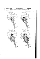
- FIGS. 2-7, inclusive, are partial perspective views illustrating in a step-by-step manner and on an enlarged scale the formation of cockled slubs in accordance with the present invention.
- a pinrality of rovings are supplied and one of these rovings carries the continuous filament with it for the purpose of maintaining the supply of continuous filament in association with the rovings until these reach the forward rolls.
- a cored roving containing a continuous filament core 11 is led to a drafting zone, preferably from the upper deck of a spinning frame creel (not shown).
- the cored roving 10 is shown passing a guide bar 12 into a trumpet guide 13 where it is joined in the form of the invention illustrated by a regular roving 14.
- the regular roving 14 passes beneath control roll 15 which bears against a driving roll 16 about which the conventional drafting apron 17 is trained, the apron 17 being tensioned and guided by roll 18 and sliding against the member 19 to complete its triangular path adjacent the front or forward rolls.
- the regular roving then passes beneath the back drafting rolls 20 and 21 and is stretched in passing through the drafting zone to the front drafting rolls or forward rolls 22 and 23.
- the cored roving 10 travels a somewhat different path going above the roll 24 and then beneath the control roll 15 in order to apply additional tension to the continuous filament 11.
- the particular manner in which the continuous filament is tensioned to regulate its supply velocity is not an important feature of the invention.
- the weighting of the back rolls 20 and 21 can be increased or the cored roving may be supplied from a roll driven at predetermined speed or the cored roving supplied through feed rolls driven at predetermined speed so that the continuous filament 1 1 is supplied under tension at a controlled rate less than the peripheral velocity of the forward rolls 22 and 23.
- the composite of rovings 1t) and 1-4 and continuous filament 11 which passes through the forward rolls 22 and 23 is generically identified by the numeral 25 and it contains spaced longitudinal segments 26, which are conventional spun yarn in structure, alternated with spaced apart cockled slubs 27, the structure of which as well as the manner of formation of which will be more fully described hereinafter.
- the composite yarn 25 is continuously twisted, as indicated by the arrow, and taken up in conventional manner by a vertically reciprocating ring spinner and rotating bobbin mechanism indicated generally at 28.
- this figure pic tures a cockled slub produced in accordance with the invention and also shows the slub producing mechanism immediately prior to slub production. More particularly, there is shown in FIG. 2, the forward rolls 22 and 23 with the rovings 10 and 14 being fed forwardly therefrom together with the forward end of a segment of the continuous filament 11. As will be seen, the rovings 10 and 14 are twisted together by the spinning indicated by arrow 28 to produce a spun yarn segment '26 of the composite slub yarn 25. There has been previously produced a cockled slub 27. As will be seen, the slub 27 comprises a more-or-less centrally positioned con tinuous filament segment 29 which extends through the slub 27.
- the trailing end of the continuous filament segment 29 is shown twisted in to the forward end of the spun yarn segment 26 as is indicated by the numeral 30. It will be observed that some of the wrappings indicated by the numeral 31 are twisted in an opposite direction with respect to the direction of twist in the spun yarn segment 26. The manner in which the oppositely twisted wrappings 31 are produced will be more fully described hereinafter.
- FIG. 2 illustrates the slub forming mechanism immediately prior to the start thereof
- FIG. 3 pictures the start of the slub forming mechanism.
- the leading end of the continuous filament 11 has been caught in the twist of the spun yarn segment 26 and, as twisting as indicated by arrow 28 continues the continuous filament 11 becomes twisted forwardly of its point of engagement with the forward rolls 22 and 23. This twisting is indicated by the numeral 32.
- the rovings 10 and 14 are fed forwardly by the forward rolls 22 and 23 more rapidly than the continuous filament 11.
- the wrappings 31 are produced, FIG. 4 showing the start of the production of wrappings 31 and FIG. 5 showing a further stage in the production of the wrappings 31. It will be seen that the wrappings 31 start at the trailing end of the spun yarn which is produced and move forwardly of the yarn (a direction opposite to the direction in which the spun yarn segment 26 is produced). As spinning indicated by arrow 28 continues, the twist in filament 11 becomes tighter as is indicated at 32 and 32".
- FIG. 6 pictures the cockled slub an instant after breale age of the continuous filament '11 as a result of excessive twist.
- the cockled slub 27 is relieved of the restraining influence of the continuous filament and moves forwardly as indicated by arrow 33 and the excess of rovings 10 and 14 wrap around the inner reverse wrappings 31 to form outer wrappings 34.
- the trailing end of the continuous filament segment 29 is still free of the rovings 10 and 14 at the stage of slub production indicated in FIG. 6.
- FIG. 7 The completed cockled slub is illustrated in FIG. 7 where it will be seen that the trailing end of the continuous filament segment 29 has been wrapped into the forward end of the new spun yarn segment 26 and the leading end of the continuous filament 11 just protrudes from between the nip of the forward rolls 22 and 23.
- the rovings 10 and 14 are spun together by the spinning indicated at 28 to produce a further spun yarn segment 26, the result of this further spinning restoring the conditions shown in FIG. 2.
- the spun yarn segment 26 will catch the forward end of the continuous filament 11 as pictured in FIG. 3 and the slub producing process will be repeated.
- the cockled slubs of the invention possess extraordinary resistance to removal.
- the cockle is constituted by wrapped rovings which are integral with the rovings constituting the body of the spun yarn and these slubs are reinforced with a segment of continuous filament.
- the spun yarn of the invention will break before the cockled slubs which are formed therein can be pulled out.
- the invention is illustrated in the accompanying table 5 A method of producing a l bi i Spun yam in Which a regular roving is Combined with a cored as recited in claim 4 in which said pre-formed yarn is ing to produce slub-containing yarns in accordan e With supplied in association with one of said rovings in the the invention. form of a cored roving.
- a method of producing a slub-containing spun yarn comprising passing a pre-formed yarn together with at least one roving between the forward rolls of a drafting device, supplying said roving to said forward rolls at a rate less than the feed velocity of said forward rolls so that said roving is drafted, supplying said pro-formed yarn at a rate less than the feed velocity of said forward rolls so that said pre-fomned yarn is under tension, said forward rolls to which said yarn and roving are supplied being weighted sufiiciently to draft said roving but insufiiciently to break said pro-formed yarn before reaching said forward rolls whereby said pro-formed yarn is fed through 6.
Description
July 17, 1962 w. E. STAMPS ETA]. 3,044,
0F PRODUCING Filed Aug. 26, 1958 3 Sheets-Sheet 1 July 17, 1962 w. E. STAMPS ETAL METHOD OF PRODUCING SLUB YARN WITH AN INTERMITTENT CORE Filed Aug. 26. 1958 3 Sheets-Sheet 2 5 July 17, 1962 w, T P 1," AL 3,044,251
METHOD 0E PRQDUGING AN INTERMI'ETEN'E C'QRE 5 Sheets-sheet 5 Filed Aug. 26. 1958 United rates i at'ent 3,044,251 METHOD OF PRODUCING SLUB YARN WITH AN INTERMETTENT CORE William E. Stamps, Allen R. Merrill, and Malcolm R.
Livingston, Charlotte, N.C., assignors to Celanese Corporation of America, New York, N.Y., a corporation of Delaware Filed Aug. 26, 1958, Ser. No. 757,374 7 Claims. (Cl. 57-157) The present invention relates to novelty spun yarns in which a spun yarn formed of staple fiber is formed with stable cockled slubs spaced apart along the length of the yarn.
Heretofore yarns containing cockled slubs have been produced unintentionally in spinning mills when attempting to spin fiber blends containing too much over-length staple. Such slubs are caused by a local inclusion of more than the normal number of fibers in a typical crosssection, and are generally unstable, being supported by only a few long fibers, and cause great difiiculties in later processing. When such slubs are encountered in normal processing, the stock is nearly always taken out of work and scrapped and the staple supplier is called upon to replace the defective staple.
In accordance with the present invention there is provided a yarn with cockled slu bs which are highly resistant to removal and are reinforced by segments of a pre-formed yarn embedded therein. The slubs of the invention are further characterized in some instances by being shorter and thicker than those produced by known mechanical slubbing methods or from so-called self-slub fiber blends. The invention includes the slub-containing spun yarn which is produced as well as methods and apparatus for the production thereof.
In accordance with one aspect of the invention, a preformed yarn is passed together with at least one rowing between the forward rolls of a drafting device. The preformed yarn may comprise a continuous filament yarn made up of one or more continuous filaments which may or may not be twisted or it may comprise a spun yarn composed of staple fibers, but for ease of reference this embodiment will be further described using a continuous filament as the pre-formed yarn. The roving is supplied at a rate less than the feed velocity of the forward rolls so that the roving is drafted. The continuous filament is similarly supplied at a rate less than the feed velocity of the forward rolls so that it is under tension in the drafting zone. The drafted roving and the continuous filament issue together from the forward roll and are twisted by the spinning ring surrounding the take-up bobbin.
The tension on the continuous filament in the drafting device is determined by the linear speed at which it is fed, the linear speed at which the forward roll of the drafting device operates and the weighting of the forward roll. Under a given set of linear speeds this weighting should be insufficient to break the continuous filament in the drafting device to avoid forming a free end which might not be carried beneath the forward roll.
Without wishing to be bound thereby, it is believed that the tension which holds back the continuous filament causes the drafted roving in advance of the forward roll to pile up about the slowly supplied continuous filament to form a slub. At the same time, the twist applied by the ring spinner to the continuous filament in advance of the forward roll causes it to become tightly twisted until it breaks. Upon breakage of the continuous filament, the slub is completed and the roving or rovings supplied by the forward rolls are twisted in conventional manner to form a length of conventional spun yarn until the leading end of the continuous filament which is slowly advanced by the forward rolls is again caught in the twist of the spun yarn which is produced whereupon the slub-forming process is repeated until the continuous filament is again broken to complete formation of another slub having a short length of continuous filament yarn embedded therein.
As will be evident, the rate of twist and the rate of continuous filament supply must be adjusted so that the continuous filament is twisted fast enough to continuously increase the number of twists per unit of length whereby the twist will increase to the breaking point. As will be evident, the twist build-up will be more rapid and breakage will occur sooner with slower filament supply and also with more rapid twisting. Similarly, breakage will occur more rapidly in filaments having a lesser capacity for resisting twist.
When the forward rolls are sufliciently weighted to draft the roving, they will normally bear sufiiciently upon the continuous filament to prevent the twist from passing through the forward rolls into the drafting zone. The filament is thus twisted more and more tightly against the point where the filament is engaged and prevented from rotating by the forward rolls.
As employed herein the term roving has reference to a loose strand of staple fibers having either a low twist or no twist in which case it is sometimes called a sliver.
The length and thickness of the slub which is produced will vary, it being evident that the slub will be longer when more length of filament passes through the forward rolls before breakage occurs. Thus, longer slubs can be formed by increasing the rate of filament supply, or by selecting a filament which requires a greater twist before it will break or by pro-twisting the filament in the opposite direction from the twist being applied in the spinning process. The thickness of the slub is basically determined by the difference between the rate of feed of the roving and the rate of feed of the continuous filament by the forward rolls. If both are supplied to the forward rolls at the rate of the back rolls of the drafting device, then the difference in front roll feed velocity will be substantially indicated by the drafting ratio. Thus, at a drafting ratio of 15: 1, the roving will emerge from forward rolls at a rate about 15 times faster than the filament. The greater the difference in feed velocities (or the greater the drafting ratio), the greater will be the thickness of the slu bs which are produced. Drafting ratios of from 5:1 to 40:1 are usable in accordance with the invention, drafting ratios of from 10:1 to 25:1 being preferred. At draft ratios less than 5:1, long irregular slubs are formed which makes processing of the yarn difficult. At draft ratios above 40:1 the slubs are very small and unstable.
In this manner, it is feasible to produce by the invention slubs which are thicker and shorter (and therefore more visible) than can be produced in other manner.
When the invention is performed using a plurality of rovings, as is preferred, those portions of the product between the slubs will be similar to conventional spun yarns produced by drafting and twisting several rovings with no continuous filament feed.
When one or more rovings are passed through a drafting device together with a yarn which passes only through the front rolls, this yarn is not drawn and the roving or rovings which are drawn are twisted about the yarn which is not drawn to produce a core yarn in which the yarn which is not drawn forms a core about which the drawn roving or rovings are wrapped.
In the invention, a core yarn is not produced because the continuous filament which corresponds to the core of the art does not extend throughout the spun yarn but is only present in spaced apart segments, and because where the continuous filament is present, it has issued forth from the front rolls at a very much slower rate than the rovings so that an increased thickness is obtained by multiple wrappings of roving or rovings and some of the wrappings are opposite in direction with respect to the direction of wrappings in the segments of spun yarn between adjacent slubs.
The invention will be more fully understood from the description which follows taken in conjunction with the accompanying drawings in which:
FIG. 1 is a side elevation diagrammatically illustrating the procedure of the invention together with the equipment employed for carrying out the process on a schematic basis;
FIGS. 2-7, inclusive, are partial perspective views illustrating in a step-by-step manner and on an enlarged scale the formation of cockled slubs in accordance with the present invention.
In a preferred form of the present invention a pinrality of rovings are supplied and one of these rovings carries the continuous filament with it for the purpose of maintaining the supply of continuous filament in association with the rovings until these reach the forward rolls.
Referring more particularly to FIG. 1, a cored roving containing a continuous filament core 11 is led to a drafting zone, preferably from the upper deck of a spinning frame creel (not shown). The cored roving 10 is shown passing a guide bar 12 into a trumpet guide 13 where it is joined in the form of the invention illustrated by a regular roving 14. The regular roving 14 passes beneath control roll 15 which bears against a driving roll 16 about which the conventional drafting apron 17 is trained, the apron 17 being tensioned and guided by roll 18 and sliding against the member 19 to complete its triangular path adjacent the front or forward rolls. The regular roving then passes beneath the back drafting rolls 20 and 21 and is stretched in passing through the drafting zone to the front drafting rolls or forward rolls 22 and 23.
The cored roving 10 travels a somewhat different path going above the roll 24 and then beneath the control roll 15 in order to apply additional tension to the continuous filament 11. As will be evident, the particular manner in which the continuous filament is tensioned to regulate its supply velocity is not an important feature of the invention. Thus, the weighting of the back rolls 20 and 21 can be increased or the cored roving may be supplied from a roll driven at predetermined speed or the cored roving supplied through feed rolls driven at predetermined speed so that the continuous filament 1 1 is supplied under tension at a controlled rate less than the peripheral velocity of the forward rolls 22 and 23.
The composite of rovings 1t) and 1-4 and continuous filament 11 which passes through the forward rolls 22 and 23 is generically identified by the numeral 25 and it contains spaced longitudinal segments 26, which are conventional spun yarn in structure, alternated with spaced apart cockled slubs 27, the structure of which as well as the manner of formation of which will be more fully described hereinafter. The composite yarn 25 is continuously twisted, as indicated by the arrow, and taken up in conventional manner by a vertically reciprocating ring spinner and rotating bobbin mechanism indicated generally at 28.
Referring more particularly to FIG. 2, this figure pic tures a cockled slub produced in accordance with the invention and also shows the slub producing mechanism immediately prior to slub production. More particularly, there is shown in FIG. 2, the forward rolls 22 and 23 with the rovings 10 and 14 being fed forwardly therefrom together with the forward end of a segment of the continuous filament 11. As will be seen, the rovings 10 and 14 are twisted together by the spinning indicated by arrow 28 to produce a spun yarn segment '26 of the composite slub yarn 25. There has been previously produced a cockled slub 27. As will be seen, the slub 27 comprises a more-or-less centrally positioned con tinuous filament segment 29 which extends through the slub 27. The trailing end of the continuous filament segment 29 is shown twisted in to the forward end of the spun yarn segment 26 as is indicated by the numeral 30. It will be observed that some of the wrappings indicated by the numeral 31 are twisted in an opposite direction with respect to the direction of twist in the spun yarn segment 26. The manner in which the oppositely twisted wrappings 31 are produced will be more fully described hereinafter.
Whereas FIG. 2 illustrates the slub forming mechanism immediately prior to the start thereof, FIG. 3, pictures the start of the slub forming mechanism. As will be seen in FIG. 3, the leading end of the continuous filament 11 has been caught in the twist of the spun yarn segment 26 and, as twisting as indicated by arrow 28 continues the continuous filament 11 becomes twisted forwardly of its point of engagement with the forward rolls 22 and 23. This twisting is indicated by the numeral 32.
As previously explained, and as will be seen by reference to FIGS. 3, 4, and 5, the rovings 10 and 14 are fed forwardly by the forward rolls 22 and 23 more rapidly than the continuous filament 11. As a result, the wrappings 31 are produced, FIG. 4 showing the start of the production of wrappings 31 and FIG. 5 showing a further stage in the production of the wrappings 31. It will be seen that the wrappings 31 start at the trailing end of the spun yarn which is produced and move forwardly of the yarn (a direction opposite to the direction in which the spun yarn segment 26 is produced). As spinning indicated by arrow 28 continues, the twist in filament 11 becomes tighter as is indicated at 32 and 32".
FIG. 6 pictures the cockled slub an instant after breale age of the continuous filament '11 as a result of excessive twist. At the instant of break-age, the cockled slub 27 is relieved of the restraining influence of the continuous filament and moves forwardly as indicated by arrow 33 and the excess of rovings 10 and 14 wrap around the inner reverse wrappings 31 to form outer wrappings 34. The trailing end of the continuous filament segment 29 is still free of the rovings 10 and 14 at the stage of slub production indicated in FIG. 6.
The completed cockled slub is illustrated in FIG. 7 where it will be seen that the trailing end of the continuous filament segment 29 has been wrapped into the forward end of the new spun yarn segment 26 and the leading end of the continuous filament 11 just protrudes from between the nip of the forward rolls 22 and 23. As will be evident, the rovings 10 and 14 are spun together by the spinning indicated at 28 to produce a further spun yarn segment 26, the result of this further spinning restoring the conditions shown in FIG. 2. Finally, the spun yarn segment 26 will catch the forward end of the continuous filament 11 as pictured in FIG. 3 and the slub producing process will be repeated.
As will be evident, the cockled slubs of the invention possess extraordinary resistance to removal. In the invention, the cockle is constituted by wrapped rovings which are integral with the rovings constituting the body of the spun yarn and these slubs are reinforced with a segment of continuous filament. In many instances, the spun yarn of the invention will break before the cockled slubs which are formed therein can be pulled out.
While slub size and slub spacing may be controlled to some extent as has been indicated hereinbefore, the procedure of the invention causes slub formation and slub size to be random to a considerable extent. This appears to be because the exact instant and point of filament breakage will vary from one slub to the next and the precise instant of engagement between the spun yarn segment and the leading end of the slowly advancing continuous filament is not precisely predetermined. Since the continuous filament is under tension with the forward rolls slipping and skidding with respect thereto, the forward movement of the continuous filament is not completely uniform and this appears to contribute to the random formation of slubs which is experienced in accordance with the invention.
said forward rolls at a slower velocity than said roving, and twisting the composite of said pre-formed yarn and said roving emerging from said forward rolls at a rate sufficient to cause the twist in said pro-formed yarn to build up until said preformed yarn breaks whereby said Specimens of the slub-containing spun yarn of the inroving will be wrapped around said pro-formed yarn to vention have been quilled and woven as filling in a runform a slub and whereby, following breakage of said prening warp and also as the warp, and still further with formed yarn, said roving will be twisted to produce a spun the slub-containing yarn of the invention constituting yam segment secured to said slub. both fill and warp. Very few of the slubs were pu led 2. A method of producing a slub-containing spun yarn out and most of the slubs withstood fabrication to proas e it d in claim 1 i which said roving and said preduce decorated woven fabrics. formed yarn are supplied to said forward rolls at a veloc- When woven into a fabric, the slubs provide a textured ity of bout to ,4 of the peripheral velocity of said appearance which is uni-directional when the novel yarn f rward To11s isemployed to constitute either the warp or the weft. It 3 A h d 1 f producing a slub-containing un yarn will be understood that the yarns of the invention may be as recited in claim 1 in which i roving and i p hy If desired, to constitute h 2 formed yarn are supplied to said forward rolls at a veloe In this event, a roughened appearance is obtained 111 the it f b t t f the peripheral velocity of said final woven product. The appearance characteristics and f rwa d 11 h hand of h Yh h Y ewoven can be con- 4. A method of producing a slub-containing spun yarn sldehably 'Varled y Yaflatloh 1n e h f 6 lengt ah as recited in claim 1 in which a plurality of rovings are spaclhg of the $111135 the y which 15 p y as W111 suppli d to said forward rolls together with said pro-formed be evident to those skilled in the art. yam,
The invention is illustrated in the accompanying table 5 A method of producing a l bi i Spun yam in Which a regular roving is Combined with a cored as recited in claim 4 in which said pre-formed yarn is ing to produce slub-containing yarns in accordan e With supplied in association with one of said rovings in the the invention. form of a cored roving.
wist. acetate. acetate. Z. Z. and X; long. 100 denier rayonlow twist 2.0 hank cellulose 2.0 hank cellulose 20:1 19 t.p.i 24 t.p.i. 10 20/1 13/1 4X yarn diam. triacetate. triacctate. Z. Z. and long. 100 denierrayon-4O t.p.i.-S twist do do 15:1 13 15.1) 1 21 t.p.i. 16 15/1 7/1 4X yarn diam. Z. 2. and 1"-1%" 5 denier cellulose acetate-low 2.5 hank rayon 2.5 hank cellulose 15:1 15 t.p 1 18 t.p.i. 10 19/1 12/1 Smali andshort twist. acetate. 2. Z.
l N orE.-Twists and counts are average values over considerable lengths.
It is to be understood that the foregoing detailed description is given merely by way of illustration and that many variations may be made therein without departing from the spirit of our invention.
Having described our invention What we desire to secure by Letters Patent is:
'1. A method of producing a slub-containing spun yarn comprising passing a pre-formed yarn together with at least one roving between the forward rolls of a drafting device, supplying said roving to said forward rolls at a rate less than the feed velocity of said forward rolls so that said roving is drafted, supplying said pro-formed yarn at a rate less than the feed velocity of said forward rolls so that said pre-fomned yarn is under tension, said forward rolls to which said yarn and roving are supplied being weighted sufiiciently to draft said roving but insufiiciently to break said pro-formed yarn before reaching said forward rolls whereby said pro-formed yarn is fed through 6. A method of producing a slub-containing spun yarn as recited in claim 1 in which said pre-formed yarn is a continuous filament yarn.
7. A method of producing a slub-containing spun yarn as recited in claim 1 in which said pre-formed yarn is a spun yarn.
References Cited in the file of this patent UNITED STATES PATENTS
Priority Applications (2)
| Application Number | Priority Date | Filing Date | Title |
|---|---|---|---|
| US757374A US3044251A (en) | 1958-08-26 | 1958-08-26 | Method of producing slub yarn with an intermittent core |
| US189945A US3144746A (en) | 1958-08-26 | 1962-03-27 | Apparatus for producing slub yarn |
Applications Claiming Priority (1)
| Application Number | Priority Date | Filing Date | Title |
|---|---|---|---|
| US757374A US3044251A (en) | 1958-08-26 | 1958-08-26 | Method of producing slub yarn with an intermittent core |
Publications (1)
| Publication Number | Publication Date |
|---|---|
| US3044251A true US3044251A (en) | 1962-07-17 |
Family
ID=25047580
Family Applications (1)
| Application Number | Title | Priority Date | Filing Date |
|---|---|---|---|
| US757374A Expired - Lifetime US3044251A (en) | 1958-08-26 | 1958-08-26 | Method of producing slub yarn with an intermittent core |
Country Status (1)
| Country | Link |
|---|---|
| US (1) | US3044251A (en) |
Cited By (2)
| Publication number | Priority date | Publication date | Assignee | Title |
|---|---|---|---|---|
| US3205648A (en) * | 1962-10-22 | 1965-09-14 | James L Lohrke | Novelty yarn |
| US3516157A (en) * | 1967-09-08 | 1970-06-23 | Western Electric Co | Methods of and apparatus for assembling terminal strips |
Citations (9)
| Publication number | Priority date | Publication date | Assignee | Title |
|---|---|---|---|---|
| US788292A (en) * | 1904-08-27 | 1905-04-25 | Jacob S Verlenden | Machine for twisting and doubling yarns. |
| US1946941A (en) * | 1933-07-18 | 1934-02-13 | Draper Corp | Yarn twisting apparatus for fancy yarns |
| US2058620A (en) * | 1935-05-02 | 1936-10-27 | Jules P Petitmermet | Yarn construction |
| US2132524A (en) * | 1937-06-21 | 1938-10-11 | Sanford Mills | Process of making yarn from continuous rayon and staple fiber |
| US2239601A (en) * | 1940-05-03 | 1941-04-22 | Clifton Yarn Mills | Novelty yarn and method of producing it |
| US2416208A (en) * | 1944-10-12 | 1947-02-18 | Unique Fibers Inc | Yarn |
| US2552210A (en) * | 1948-01-29 | 1951-05-08 | Walter B Parker | Method of making ply yarn |
| US2745240A (en) * | 1950-05-18 | 1956-05-15 | Bates Mfg Co | Composite filament and staple yarn |
| US2845771A (en) * | 1954-10-22 | 1958-08-05 | Jr Charles Eugene Neisler | Direct spun shantung yarn and method of making same |
-
1958
- 1958-08-26 US US757374A patent/US3044251A/en not_active Expired - Lifetime
Patent Citations (9)
| Publication number | Priority date | Publication date | Assignee | Title |
|---|---|---|---|---|
| US788292A (en) * | 1904-08-27 | 1905-04-25 | Jacob S Verlenden | Machine for twisting and doubling yarns. |
| US1946941A (en) * | 1933-07-18 | 1934-02-13 | Draper Corp | Yarn twisting apparatus for fancy yarns |
| US2058620A (en) * | 1935-05-02 | 1936-10-27 | Jules P Petitmermet | Yarn construction |
| US2132524A (en) * | 1937-06-21 | 1938-10-11 | Sanford Mills | Process of making yarn from continuous rayon and staple fiber |
| US2239601A (en) * | 1940-05-03 | 1941-04-22 | Clifton Yarn Mills | Novelty yarn and method of producing it |
| US2416208A (en) * | 1944-10-12 | 1947-02-18 | Unique Fibers Inc | Yarn |
| US2552210A (en) * | 1948-01-29 | 1951-05-08 | Walter B Parker | Method of making ply yarn |
| US2745240A (en) * | 1950-05-18 | 1956-05-15 | Bates Mfg Co | Composite filament and staple yarn |
| US2845771A (en) * | 1954-10-22 | 1958-08-05 | Jr Charles Eugene Neisler | Direct spun shantung yarn and method of making same |
Cited By (2)
| Publication number | Priority date | Publication date | Assignee | Title |
|---|---|---|---|---|
| US3205648A (en) * | 1962-10-22 | 1965-09-14 | James L Lohrke | Novelty yarn |
| US3516157A (en) * | 1967-09-08 | 1970-06-23 | Western Electric Co | Methods of and apparatus for assembling terminal strips |
Similar Documents
| Publication | Publication Date | Title |
|---|---|---|
| US3225533A (en) | Apparatus and process for forming yarns and other twisted assemblies | |
| US4069656A (en) | Composite spun yarn and process for producing the same | |
| EP3725923A1 (en) | Composite yarn, fabric comprising the composite yarn, method for producing a composite yarn and arrangement for producing a composite yarn | |
| US2990673A (en) | Process and apparatus for producing core yarns | |
| JPS6028936B2 (en) | Yarn manufacturing method | |
| US3099907A (en) | Process for obtaining textile end products using discontinuous fibers | |
| US3070950A (en) | Method of producing a composite yarn | |
| US2859583A (en) | Apparatus for producing core yarns | |
| US2946181A (en) | Production of twistless yarns by direct spinning to tow, sizing the tow, false twisting and winding | |
| US3460338A (en) | Stretch yarn | |
| US3394538A (en) | Spun yarn | |
| US3309863A (en) | Production of elastic yarns on the woolen system | |
| US3303640A (en) | Method of producing composite elastic yarn | |
| US2160178A (en) | Yarn and fabric and method of making same | |
| US3844098A (en) | Apparatus and method for the manufacture of twisted and plied yarn | |
| US3255579A (en) | Production of composite stretch yarns | |
| US3044251A (en) | Method of producing slub yarn with an intermittent core | |
| US3123972A (en) | Slub yarn | |
| GB2060723A (en) | Winding of yarns from open- end spinners onto common former | |
| US3053040A (en) | Method and apparatus for producing a slubbed core yarn | |
| US3153316A (en) | Bulky yarn and method of producing the yarn | |
| US2845771A (en) | Direct spun shantung yarn and method of making same | |
| US4866924A (en) | Two-component yarn | |
| US3144746A (en) | Apparatus for producing slub yarn | |
| US3199283A (en) | Strong slub yarn |