US3003268A - Sign construction - Google Patents
Sign construction Download PDFInfo
- Publication number
- US3003268A US3003268A US821202A US82120259A US3003268A US 3003268 A US3003268 A US 3003268A US 821202 A US821202 A US 821202A US 82120259 A US82120259 A US 82120259A US 3003268 A US3003268 A US 3003268A
- Authority
- US
- United States
- Prior art keywords
- sign
- elements
- arrester
- construction
- strikers
- Prior art date
- Legal status (The legal status is an assumption and is not a legal conclusion. Google has not performed a legal analysis and makes no representation as to the accuracy of the status listed.)
- Expired - Lifetime
Links
Images
Classifications
-
- G—PHYSICS
- G09—EDUCATION; CRYPTOGRAPHY; DISPLAY; ADVERTISING; SEALS
- G09F—DISPLAYING; ADVERTISING; SIGNS; LABELS OR NAME-PLATES; SEALS
- G09F11/00—Indicating arrangements for variable information in which the complete information is permanently attached to a movable support which brings it to the display position
- G09F11/02—Indicating arrangements for variable information in which the complete information is permanently attached to a movable support which brings it to the display position the display elements being secured to rotating members, e.g. drums, spindles
- G09F11/025—Indicating arrangements for variable information in which the complete information is permanently attached to a movable support which brings it to the display position the display elements being secured to rotating members, e.g. drums, spindles the members being rotated simultaneously, each face of the member carrying a part of the sign
Definitions
- FIG. 2 I2 f' 1 [8 u WIOHCJS JTMM JNVENTOR. EDMUND CHAN A TTORNEVS United States Patent (3 3,003,268 SIGN CONSTRUCTION Edmund Chan, 1917 Broderick St., San Francisco 15, Calif. Filed June 18, 1959, Ser. No. 821,202 10 Claims. (Cl. 40-33)
- This invention relates generally to a sign construction for use in advertising or display activities, for example, in self-service markets, department stores and the like.
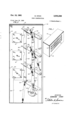
- FIGURE 1 is a view in perspective of a sign construction embodying the invention
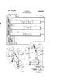
- FIGURE 2 is a view in rear elevation of the sign construction of FIGURE 1;
- FIGURE 3 is aview in vertical section on an enlarged scale, along the line 3-3 of FIGURE 2;
- FIGURES 4 and 5 are detail views, like FIGURE 3, showing difierent stages in the operation of the device.
- a sign construction of the present invention comprises a plurality of rotatably mounted sign elements by which a Wide variety of word combinations can be continuously made available for display.
- the sign elements are arranged in parallelism and mounted for rotation about horizontal axes.
- the elements each have a plurality of sides bearing word-forming indicia which are most conveniently provided on .
- An actuating mechanism which may include a plurality of pivotally mounted strikers operates to rotate the sign elements in unison, to initiate the formation of a new word combination.
- Arrester means then operate to simultaneously engage and stop the rotation of the elements, and to permit display of a particular word combination.
- Synchronizing means are also provided to insure a desired successive operation of the actuator means and arrester means, preferably in a continuous cycle.
- three sign elements of substantially square cross sectional configuration are employed.
- Each of the four sides of a sign element is provided with a different word or words, compatible in phonetic relationship with the words of the other sign elements.
- the words of the sign element are chosen so that any combination of three sides presented by the three elements forms a sentence.
- the number of possible word combinations is a geometric progression according to the following formula where S is the number of sides of a sign element, n is the total number of sign elements in the device, and W is the "ice number of word combinations possible.
- the illustrated device employing three sign elements each having four sides will provide sixty-four possible word combinations for display.
- 10 indicates gen erally a sign construction including an external housing 12.
- the housing can be self-supporting and have an open back and a plurality of display openings 14 in a front face.
- Supported for rotation within the housing are a plurality of sign elements 16.
- These sign elements are supported on spindles 18 which preferably are arranged in substantial parallelism.
- the sign elements are provided with projecting rods 20. As will appear, these rods are adapted to engage with the actuating means causing rotation of the elements.
- the motor has a drive shaft 24 journalled in the upstanding supports 26 and 28, the latter also forming the means of support for the actuator and arrester mechanisms.
- the actuator mechanism 30 is shown to comprise a plurality of actuator arms 32 mounted for pivotal movement relative to the support 28.
- the arms 32 are adapted to operate in unison by means of a vertical actuator bar 34 pivoted to the arms at their midpoint.
- Each arm also supports a striker 36 for pivotal movements about a pivot point 38.
- These strikers preferably have enlarged rear portions each provided with a stop 40.
- the latter are connected to the actuator bar 34 by means of springs 42 which bias the strikers into a striking position.
- the strikers function on downward pivotal movement of the actuator bar 34 to engage the projecting rods 20 of the sign elements and to rotate the latter sharply in a clockwise direction.
- the stops 40 lock the strikers against pivotal movement relative to the arms 32.
- the strikers On upward or reverse movement of the actuator bar, the strikers function as pawls and pivot against the pressure of the springs 42 about the pivot points 38. When the strikers have passed the rods 20 of the sign elements, they are returned by the springs to the striking position (FIGURE 3).
- the arrester mechanism 50 functions to simultaneously engage and stop the rotation of thesign elements.
- the result is a random selection of a word combination to appear through the windows 14 of the housing.
- the illustrated arrester mechanism includes the arms 52, likewise pivoted on the support 28. These arms carry the vertically extending arrester bar 54 at their outer ends. As will be understood, downward pivotal movement of the arrester mechanism causes the bar 54 to move laterally into a position of engagement with the sign elements 16 as particularly illustrated in FIGURE 5. Preferably the bar 54 is notched, as at 56, to permit passage of the rotating corners of the sign elements, just prior to engagement for display. This insures perpendicular alignment of the outer display faces of the sign elements, in the arrested display position.
- the striking or spinning action of the mechanism 30 and the arresting action of the mechanism 50 are synchronized to successive portions of a continuous cycle. This is accomplished in the 3. illustrated apparatus. by means of the phase relationship of the rotating earns 60, 64, carried by the drive shaft 24. Rotation of. the actuator cam 60 causes actuating mechanism 30 to be raised gradually into a striking position against the pressure of the spring 62. This function is shown in FIGURES 3, 4 and 5, which illustrate the sequence of movement of the actuating mechanism downward through the striking or sign spinning stroke, during .Which the strikers are in locked position, and its gradual return movement to the striking position, during which the strikers pivot downward to permit passage of the rods 2.0.
- Rotation-.01 thearrestercam 6.4- causes the arrester mechanism 50 to. be-sharply; lifted against the pressure of the spring 55 to an upper disengaged position. (FIGURES 3 and 4) and to be quickly" returned to a lower arresting or sign. engaging; position (FIGURE 5).
- the cams are enabled to operate insuccession to first cause a striking or spinning of the sign elements, and a successive engaging or stoppingofi therelements to-produce a random Word combination.
- thecycle can be repeated to 'make similar random; selections with each rotation of. the
- V I have found that satisfactory operation of my device is obtained when they shaft 24' is rotated at a speed between: about 0.5. and. 4v r.p.m-. Such operation will act to produce a new word. combination every 15-120 seconds,v depending upon the. particular speed of' rotation. Of course, slower or faster: speeds of rotation are possible: without. appreciable variation in. the principle of operation.
- the arresting bar 54 has; just been raised and disengaged from the rear faces of the sign. element, a position it will retain for-about 15 to 40 rotation of the shaft 24 depending on the particular design of the cam 64.
- the actuating mechanism 30 has simultaneously been-:raisedto-an uppermost position ready for; the striking operation.
- thearrester bar Upon further rotation of the shaft 24 to the position of FIGURE. 4 (counterclockwise in the drawing), thearrester bar will momentarily remain disengaged.
- the spring. 62 causes the actuator bar 34 topivot sharply: downward, and the strikers 36 toengage the: projecting rods 20. of the sign elements.
- the strikers are held in locked: position by the stops 40 so that a rapid spinning movement. is imparted to the sign elements 16, about their axes 18.
- the. arresting: mechanism is pivoted 'downward. causing the bar 54 to engage the rear faces of the sign; elements, thereby stopping their rotation. This movement is. causedby the downward pull of the spring 55.. 'Itiwill be, noted thatthe construction is such that the; strikers remain in'the down position until the arrester bar-54has: engaged; and stopped the sign elements in the display position, which comprises the major part of. the cycle. Thereafter, the actuating mechanism is first. returned to the raised.
- the arrester bar remaining in the sign engaging position.
- movement, illustrated in FIGURE 5 the striker elements; rock abouttheir pivots 38 so as to pass the; rods. 2.0,v
- the arrester cam 64 functions to again raise thebar; 5410. release the sign elements for spinning duringthesubsequent downward or actuating stroke of the strikers; In: this. way, successive, spinning and displayportions: of; the. cycle: ofv the sign are made possible in a fully automatic continuous operation.
- movable means providing a wide; variety: of random word combinations for display, said means comprising a plurality of sign elements arranged in parallelism and mounted for rotation about their axes, said elements each having at least three sides bearing word-forming indicia, striking means adapted to impart free rotation to said sign elements, arrester means adapted to engage and stop the free rotation of said elements, and means synchronizing the operation of said striking and arrester means to successive portions of a continuous cycle, whereby different random combinations ofword-forming indicia are continuously and cyclically produced by said sign construction.
- said arrester means includes a vertically and laterally movable arrester bar adapted to simultaneously engage a side of each of said sign elements.
- a sign construction as in claim 1 wherein said synchronizing means includes a pair of rotatablev cams locked to adrive shaft, one controlling operation of the striking means. and the other the operation of the arrester means.
- movable means providing a wide variety of random. word combinations for display, said means comprising .a plurality of sign elements arranged in parallelism and mounted. for rotation about their axes, said elements each having at least three sides bearing word-forming indicia, pivotally mounted striking means adapted on operation tcrsnike and impart free rotation to. said sign. elements, a pivotallymounted arrester bar adapted tov engage and, stop the free rotation of said sign elements, and cam means synchronizing the pivotal, operation of said striking. means and said arrester means to successive. portions of. acontinuous cycle, whereby diiferent random combinationsof words are continuously and. cyclically. produced by said sign construction.
- strika ing means includes a plurality. ofpivotally mounted actuator arms carrying pivotally mounted strikers at their outer free ends, said. strikersbeing adapted to operate in unison to rotate said sign. elements.
- said actuator means including a plurality of pivotally mounted actuator arms, an actuator bar carried by said arms, pivotally mounted strikers carried by the free ends of said arms, and resilient means biasing said strikers into a striking position; pivotally mounted arrester means adapted to simultaneously engage and thereby stop the free rotation of said sign elements, said arrester means including a plurality of pivotally mounted arrester arms and an arrester bar carried by the free ends of said arms; and means synchronizing the operation of said actuator means and said arrester means, said synchronizing means including a continuously operating shaft and a pair of cams, one of said cams being engageable to shift said actuator means and the other being engageable to shift said arrester means.
Description
Oct. 10, 1961 E. CHAN 3,003,268
SIGN CONSTRUCTION Filed June 18, 1959 2 Sheets-Sheet l INVENTOR. EDMUND CHAN A TTO/PNE VS Oct. 10, 1961 E. CHAN 3,003,268
SIGN CONSTRUCTION Filed June 18, 1959 2 Sheets-Sheet 2 42 FIG. 2 I2 f' 1 [8 u WIOHCJS JTMM JNVENTOR. EDMUND CHAN A TTORNEVS United States Patent (3 3,003,268 SIGN CONSTRUCTION Edmund Chan, 1917 Broderick St., San Francisco 15, Calif. Filed June 18, 1959, Ser. No. 821,202 10 Claims. (Cl. 40-33) This invention relates generally to a sign construction for use in advertising or display activities, for example, in self-service markets, department stores and the like.
In general, it' is an object of the invention to improve upon the construction of such devices, particularly with respect to means making possible a wide variety of word combinations for display.
It is another object of the invention to provide a sign construction having a plurality of rotatable sign elements, each having a plurality of sides bearing word-forming indicia, by which a plurality of successive substantially nonrepetitive word combinations can be made'available for display.
Additional objects and advantages of the invention will appear from the following description and from the drawings in which:
FIGURE 1 is a view in perspective of a sign construction embodying the invention;
FIGURE 2 is a view in rear elevation of the sign construction of FIGURE 1;
FIGURE 3 is aview in vertical section on an enlarged scale, along the line 3-3 of FIGURE 2; and
FIGURES 4 and 5 are detail views, like FIGURE 3, showing difierent stages in the operation of the device.
Generally stated, a sign construction of the present invention comprises a plurality of rotatably mounted sign elements by which a Wide variety of word combinations can be continuously made available for display. Preferably the sign elements are arranged in parallelism and mounted for rotation about horizontal axes. The elements each have a plurality of sides bearing word-forming indicia which are most conveniently provided on .a sign element of regular polygonal cross section, An actuating mechanism which may include a plurality of pivotally mounted strikers operates to rotate the sign elements in unison, to initiate the formation of a new word combination. Arrester means then operate to simultaneously engage and stop the rotation of the elements, and to permit display of a particular word combination. Synchronizing means are also provided to insure a desired successive operation of the actuator means and arrester means, preferably in a continuous cycle.
In a typical sign construction, for example, as illustrated, three sign elements of substantially square cross sectional configuration are employed. Each of the four sides of a sign element is provided with a different word or words, compatible in phonetic relationship with the words of the other sign elements. The words of the sign element are chosen so that any combination of three sides presented by the three elements forms a sentence. As will be understood by one skilled in this art, the number of possible word combinations is a geometric progression according to the following formula where S is the number of sides of a sign element, n is the total number of sign elements in the device, and W is the "ice number of word combinations possible. By way of illustration, the illustrated device employing three sign elements each having four sides will provide sixty-four possible word combinations for display.
Referring to the drawings in detail, 10 indicates gen erally a sign construction including an external housing 12. The housing can be self-supporting and have an open back and a plurality of display openings 14 in a front face. Supported for rotation within the housing are a plurality of sign elements 16. These sign elements are supported on spindles 18 which preferably are arranged in substantial parallelism. At their operating ends, the sign elements are provided with projecting rods 20. As will appear, these rods are adapted to engage with the actuating means causing rotation of the elements.
Any suitable source of power such as the electric motor 22 can be employed to operate the sign. In the illustrated apparatus, the motor has a drive shaft 24 journalled in the upstanding supports 26 and 28, the latter also forming the means of support for the actuator and arrester mechanisms.
Referring to FIGURE 3, the actuator mechanism 30 is shown to comprise a plurality of actuator arms 32 mounted for pivotal movement relative to the support 28. The arms 32 are adapted to operate in unison by means of a vertical actuator bar 34 pivoted to the arms at their midpoint. Each arm also supports a striker 36 for pivotal movements about a pivot point 38. 'These strikers preferably have enlarged rear portions each provided with a stop 40. The latter are connected to the actuator bar 34 by means of springs 42 which bias the strikers into a striking position. The strikers function on downward pivotal movement of the actuator bar 34 to engage the projecting rods 20 of the sign elements and to rotate the latter sharply in a clockwise direction. During this movement, the stops 40 lock the strikers against pivotal movement relative to the arms 32. On upward or reverse movement of the actuator bar, the strikers function as pawls and pivot against the pressure of the springs 42 about the pivot points 38. When the strikers have passed the rods 20 of the sign elements, they are returned by the springs to the striking position (FIGURE 3).
Assuming rotation of the sign elements (as a result of actuation by the means 30) the arrester mechanism 50 functions to simultaneously engage and stop the rotation of thesign elements. The result is a random selection of a word combination to appear through the windows 14 of the housing.
The illustrated arrester mechanism includes the arms 52, likewise pivoted on the support 28. These arms carry the vertically extending arrester bar 54 at their outer ends. As will be understood, downward pivotal movement of the arrester mechanism causes the bar 54 to move laterally into a position of engagement with the sign elements 16 as particularly illustrated in FIGURE 5. Preferably the bar 54 is notched, as at 56, to permit passage of the rotating corners of the sign elements, just prior to engagement for display. This insures perpendicular alignment of the outer display faces of the sign elements, in the arrested display position.
It is a feature of the invention that the striking or spinning action of the mechanism 30 and the arresting action of the mechanism 50 are synchronized to successive portions of a continuous cycle. This is accomplished in the 3. illustrated apparatus. by means of the phase relationship of the rotating earns 60, 64, carried by the drive shaft 24. Rotation of. the actuator cam 60 causes actuating mechanism 30 to be raised gradually into a striking position against the pressure of the spring 62. This function is shown in FIGURES 3, 4 and 5, which illustrate the sequence of movement of the actuating mechanism downward through the striking or sign spinning stroke, during .Which the strikers are in locked position, and its gradual return movement to the striking position, during which the strikers pivot downward to permit passage of the rods 2.0. Rotation-.01 thearrestercam 6.4- causes the arrester mechanism 50 to. be-sharply; lifted against the pressure of the spring 55 to an upper disengaged position. (FIGURES 3 and 4) and to be quickly" returned to a lower arresting or sign. engaging; position (FIGURE 5). By a positioning of the'cams in an out;of phase. relationship relative to the drive shaft, say 15- to.40.' out of phase, the cams are enabled to operate insuccession to first cause a striking or spinning of the sign elements, and a successive engaging or stoppingofi therelements to-produce a random Word combination. Moreover, thecycle can be repeated to 'make similar random; selections with each rotation of. the
drive shaft. V
V I have found that satisfactory operation of my device is obtained when they shaft 24' is rotated at a speed between: about 0.5. and. 4v r.p.m-. Such operation will act to produce a new word. combination every 15-120 seconds,v depending upon the. particular speed of' rotation. Of course, slower or faster: speeds of rotation are possible: without. appreciable variation in. the principle of operation.
Theoperationof my new. sign; construction can be summarized asfollows:
Assuming a positioning of the parts as in FIGURE 3, the arresting bar 54 has; just been raised and disengaged from the rear faces of the sign. element, a position it will retain for-about 15 to 40 rotation of the shaft 24 depending on the particular design of the cam 64. The actuating mechanism 30 has simultaneously been-:raisedto-an uppermost position ready for; the striking operation. Upon further rotation of the shaft 24 to the position of FIGURE. 4 (counterclockwise in the drawing), thearrester bar will momentarily remain disengaged. However; the spring. 62 causes the actuator bar 34 topivot sharply: downward, and the strikers 36 toengage the: projecting rods 20. of the sign elements. During-this striking movemennthe strikers are held in locked: position by the stops 40 so that a rapid spinning movement. is imparted to the sign elements 16, about their axes 18. Upon continued rotation of the drive. shaft, the. arresting: mechanism is pivoted 'downward. causing the bar 54 to engage the rear faces of the sign; elements, thereby stopping their rotation. This movement is. causedby the downward pull of the spring 55.. 'Itiwill be, noted thatthe construction is such that the; strikers remain in'the down position until the arrester bar-54has: engaged; and stopped the sign elements in the display position, which comprises the major part of. the cycle. Thereafter, the actuating mechanism is first. returned to the raised. position of FIGURE 3, the arrester bar: remaining in the sign engaging position. During this; movement, illustrated in FIGURE 5, the striker elements; rock abouttheir pivots 38 so as to pass the; rods. 2.0,v When the strikershavereached an uppermQ t position, the arrester cam 64 functions to again raise thebar; 5410. release the sign elements for spinning duringthesubsequent downward or actuating stroke of the strikers; In: this. way, successive, spinning and displayportions: of; the. cycle: ofv the sign are made possible in a fully automatic continuous operation.
The; above descri tion has related specifically to a sign: ccnstructionemploying threeasign elements 16, each having; flour: sides; Itiwill. be evidentzto. those skilled in thisartnhcgiveventthat many variations. in this construction as. well as. other. differening. embodiments. and applications are possible without a departure from the spirit and scope of the invention. For example, it is contemplated that the sign elements may have any number of sides; likewise the number of sign elements'may be substantially different. Thus signs employing as many as five elements each having five or more sides are contemplated. Such variation would, of course, greatly increase the number of possible word combinations so that the use is limited only. by the'imagination and ingenuity of the user in conceiving slogans or sentences for display. Accordingly it, should be understood that the disclosuresand descnption'hereinare purely illustrative and not intended to be in. any sense limiting.
I claim: a 7 a p 1. In a fully automatic; sign construction, movable means providing a wide; variety: of random word combinations for display, said means comprising a plurality of sign elements arranged in parallelism and mounted for rotation about their axes, said elements each having at least three sides bearing word-forming indicia, striking means adapted to impart free rotation to said sign elements, arrester means adapted to engage and stop the free rotation of said elements, and means synchronizing the operation of said striking and arrester means to successive portions of a continuous cycle, whereby different random combinations ofword-forming indicia are continuously and cyclically produced by said sign construction.
2. A sign construction as in claim 1 wherein the cross sectional configuration of a sign element is a regular polygon.
3. A sign construction asin claim 1 wherein said striking means includes reciprocally mounted strikers.
4. A sign construction as in claim 1, wherein said arrester means includes a vertically and laterally movable arrester bar adapted to simultaneously engage a side of each of said sign elements. 7
5. A sign construction as in claim 1 wherein said synchronizing means includes a pair of rotatablev cams locked to adrive shaft, one controlling operation of the striking means. and the other the operation of the arrester means.
6. In a sign construction, movable means providing a wide variety of random. word combinations for display, said means comprising .a plurality of sign elements arranged in parallelism and mounted. for rotation about their axes, said elements each having at least three sides bearing word-forming indicia, pivotally mounted striking means adapted on operation tcrsnike and impart free rotation to. said sign. elements, a pivotallymounted arrester bar adapted tov engage and, stop the free rotation of said sign elements, and cam means synchronizing the pivotal, operation of said striking. means and said arrester means to successive. portions of. acontinuous cycle, whereby diiferent random combinationsof words are continuously and. cyclically. produced by said sign construction.
7. A sign construction as.in.claim 6 wherein said strika ing means includes a plurality. ofpivotally mounted actuator arms carrying pivotally mounted strikers at their outer free ends, said. strikersbeing adapted to operate in unison to rotate said sign. elements. I
8. A sign construction asin claim 7 wherein said strikers are mounted as pawls to'permit pivotal movements ofthe. strikers .in. one direction and to prevent such movements in a reverse direction.
9. In a sign construction, means providing a wide variety of random word combinations for display, said means comprising: a plurality of sign elements arranged in parallelism and mouned for free rotation about their axes, said sign elements being of regular polygonal cross section so as to present a plurality of sides bearing wordforming indicia; actuator: means operable tostrike and cause freeirotation'rof said" sign=elements =about their axes,
said actuator means including a plurality of pivotally mounted actuator arms, an actuator bar carried by said arms, pivotally mounted strikers carried by the free ends of said arms, and resilient means biasing said strikers into a striking position; pivotally mounted arrester means adapted to simultaneously engage and thereby stop the free rotation of said sign elements, said arrester means including a plurality of pivotally mounted arrester arms and an arrester bar carried by the free ends of said arms; and means synchronizing the operation of said actuator means and said arrester means, said synchronizing means including a continuously operating shaft and a pair of cams, one of said cams being engageable to shift said actuator means and the other being engageable to shift said arrester means.
10. A sign construction as in claim 8 wherein said arrester bar is notched to avoid interference with rotating corners of the sign elements, just before contact of the bar with rear sides of said sign elements.
References Cited in the file of this patent UNITED STATES PATENTS
Priority Applications (1)
| Application Number | Priority Date | Filing Date | Title |
|---|---|---|---|
| US821202A US3003268A (en) | 1959-06-18 | 1959-06-18 | Sign construction |
Applications Claiming Priority (1)
| Application Number | Priority Date | Filing Date | Title |
|---|---|---|---|
| US821202A US3003268A (en) | 1959-06-18 | 1959-06-18 | Sign construction |
Publications (1)
| Publication Number | Publication Date |
|---|---|
| US3003268A true US3003268A (en) | 1961-10-10 |
Family
ID=25232787
Family Applications (1)
| Application Number | Title | Priority Date | Filing Date |
|---|---|---|---|
| US821202A Expired - Lifetime US3003268A (en) | 1959-06-18 | 1959-06-18 | Sign construction |
Country Status (1)
| Country | Link |
|---|---|
| US (1) | US3003268A (en) |
Cited By (4)
| Publication number | Priority date | Publication date | Assignee | Title |
|---|---|---|---|---|
| US3400366A (en) * | 1965-06-21 | 1968-09-03 | Donald M. Downing | Traffic period control sign having movable shutters |
| US3704683A (en) * | 1970-09-14 | 1972-12-05 | E John Summersby | Visual communication apparatus |
| US4021946A (en) * | 1974-10-03 | 1977-05-10 | F & M Systems, Co., A Division Of Fischbach And Moore, Incorporated | Multielement changeable sign display |
| US4912442A (en) * | 1987-12-17 | 1990-03-27 | Black Fred M | Scanned electromechanical alphanumeric display |
Citations (6)
| Publication number | Priority date | Publication date | Assignee | Title |
|---|---|---|---|---|
| US1058698A (en) * | 1912-08-05 | 1913-04-08 | Adolph O Goldstein | Advertising device. |
| US1077885A (en) * | 1912-10-22 | 1913-11-04 | James H La Pearl | Changeable advertising-sign. |
| US1362542A (en) * | 1920-12-14 | rogers | ||
| US1806722A (en) * | 1931-05-26 | von der lippe-lipski | ||
| US2839855A (en) * | 1956-04-26 | 1958-06-24 | John M Palmer | Displays |
| US2887085A (en) * | 1957-04-08 | 1959-05-19 | Aiken William Ross | Signalling device |
-
1959
- 1959-06-18 US US821202A patent/US3003268A/en not_active Expired - Lifetime
Patent Citations (6)
| Publication number | Priority date | Publication date | Assignee | Title |
|---|---|---|---|---|
| US1362542A (en) * | 1920-12-14 | rogers | ||
| US1806722A (en) * | 1931-05-26 | von der lippe-lipski | ||
| US1058698A (en) * | 1912-08-05 | 1913-04-08 | Adolph O Goldstein | Advertising device. |
| US1077885A (en) * | 1912-10-22 | 1913-11-04 | James H La Pearl | Changeable advertising-sign. |
| US2839855A (en) * | 1956-04-26 | 1958-06-24 | John M Palmer | Displays |
| US2887085A (en) * | 1957-04-08 | 1959-05-19 | Aiken William Ross | Signalling device |
Cited By (4)
| Publication number | Priority date | Publication date | Assignee | Title |
|---|---|---|---|---|
| US3400366A (en) * | 1965-06-21 | 1968-09-03 | Donald M. Downing | Traffic period control sign having movable shutters |
| US3704683A (en) * | 1970-09-14 | 1972-12-05 | E John Summersby | Visual communication apparatus |
| US4021946A (en) * | 1974-10-03 | 1977-05-10 | F & M Systems, Co., A Division Of Fischbach And Moore, Incorporated | Multielement changeable sign display |
| US4912442A (en) * | 1987-12-17 | 1990-03-27 | Black Fred M | Scanned electromechanical alphanumeric display |
Similar Documents
| Publication | Publication Date | Title |
|---|---|---|
| US2209858A (en) | Intermittent movement for display devices | |
| US3003268A (en) | Sign construction | |
| US2840949A (en) | Music box driven dancing figurine | |
| US2763078A (en) | Apparatus for producing colored display patterns | |
| US2195249A (en) | Display machine | |
| US1865758A (en) | Display or decoration device | |
| US1652335A (en) | Display device | |
| US2814893A (en) | Display device | |
| US2192072A (en) | Automatic advertising apparatus | |
| US3148452A (en) | Motion conversion device | |
| US1069122A (en) | Advertising device. | |
| US1644239A (en) | Apparatus for producing series of signs | |
| US2244242A (en) | Printing machine | |
| US2646639A (en) | Animated display device | |
| US2194508A (en) | Electric clock | |
| US2117882A (en) | Display device | |
| US342737A (en) | Kindergarten apparatus for teaching spelling | |
| US1328192A (en) | Exhibiting device | |
| US1444339A (en) | Automatic illuminated changeable sign | |
| US2266676A (en) | Advertising sign | |
| US2838861A (en) | Activated display sign | |
| US1003094A (en) | Dissolving-view machine. | |
| KR200158770Y1 (en) | Multiple image expression equipment | |
| US1183763A (en) | Changeable exhibitor. | |
| US1201727A (en) | Picture-projecting machine. |