US2995155A - Wire bending die mechanism - Google Patents
Wire bending die mechanism Download PDFInfo
- Publication number
- US2995155A US2995155A US600021A US60002156A US2995155A US 2995155 A US2995155 A US 2995155A US 600021 A US600021 A US 600021A US 60002156 A US60002156 A US 60002156A US 2995155 A US2995155 A US 2995155A
- Authority
- US
- United States
- Prior art keywords
- wire
- die
- dies
- slides
- forwardly
- Prior art date
- Legal status (The legal status is an assumption and is not a legal conclusion. Google has not performed a legal analysis and makes no representation as to the accuracy of the status listed.)
- Expired - Lifetime
Links
- 238000005452 bending Methods 0.000 title description 29
- 125000006850 spacer group Chemical group 0.000 description 10
- 238000010276 construction Methods 0.000 description 6
- 238000012986 modification Methods 0.000 description 4
- 230000004048 modification Effects 0.000 description 4
- 230000003247 decreasing effect Effects 0.000 description 3
- 238000005482 strain hardening Methods 0.000 description 3
- 238000000034 method Methods 0.000 description 2
- 239000007795 chemical reaction product Substances 0.000 description 1
- 230000001186 cumulative effect Effects 0.000 description 1
- 230000001419 dependent effect Effects 0.000 description 1
- 238000006073 displacement reaction Methods 0.000 description 1
- 238000004519 manufacturing process Methods 0.000 description 1
- 239000002184 metal Substances 0.000 description 1
- 239000000047 product Substances 0.000 description 1
Images


Classifications
-
- B—PERFORMING OPERATIONS; TRANSPORTING
- B21—MECHANICAL METAL-WORKING WITHOUT ESSENTIALLY REMOVING MATERIAL; PUNCHING METAL
- B21F—WORKING OR PROCESSING OF METAL WIRE
- B21F35/00—Making springs from wire
- B21F35/04—Making flat springs, e.g. sinus springs
Definitions
- This invention relates to wire bending machines and more particularly to novel mechanism of improved design for bending wire lengths into sinusoidal and other shapes without cold working the wire at critical points of bend and introducing stresses which cannot be effectively relieved in a normalizing furnace.
- One of the prime objects of the instant invention is to design bending mechanism of simplified and less costly construction wherein reciprocatory die slides disposed on opposite sides of a wire are provided with cam controlled, rockable dies which cooperate to progressively form or fold a wire in a smooth, natural manner so that the metal displacement caused by the bending does not create torsional or other stresses at the points of bend.
- This radius at each point of bend is governed by the mechanism for forming the wire and obviously some radius must be formed at the points of bend sincethe spring would fracture in the bending operation if no radii whatever were provided. If mechanism employing pin type dies is employed to bend the wire as in some prior art machines and it is desired to bend several wire lengths at a time the pins must be of relatively large diameter and the radii at the points of bend will be large.
- the novel die mechanism which will be described contemplates a new method of forming the wire with cam controlled, pivotal dies which can form minimum radii in the wire at the points of bend. Initially slightly closed loops are formed in the forward strokes of the die slides and thence on the withdrawal stroke the mouths of the loops are allowed to spread to substantially the extent desired.
- Another object of the invention is to provide pivotal dies which develop additional leverage by being mounted ofi center on the die slides.
- Still another object of the invention is to provide wire bending mechanism which is easily disengaged from the formed Wire without abrading the wire and creating localized work hardened sections which would later easily fracture.
- a further object of the invention is to design die units having cam surfaces which can be very readily moved forwardly or rearwardly to control the depth of the bends as desired.
- Another object of the invention is to provide wire bending die mechanism which is adapted to use on a universal machine of the type described in the instant assignees copending application Serial No. 482,940, filed January 20, 1955 and now Patent No. 2,869,590 by Joseph H. Hoern wherein the die housings are laterally movable and with which a wide variety of wire shapes of varying sizes can be formed.
- a further object of the invention is to provide wire bending die mechanism which can be readily set up on such a machine in a minimum length of time to bend wire lengths with precision accuracy.
- Another object of the invention is to design wire bending mechanism which is efiicient and reliable in opera tion and by means of which bending can be accomplished in a highly economical manner with a minimum of scrap ping.
- a still further object of the invention is to provide wire bending mechanism of simplified and durable construction which can be very economically manufactured and assembled.
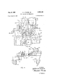
- FIG. 1 is a fragmentary, top plan view of the die unit showing a wire in position between the dies, certain of the centrally located dies being shown as moved forwardly to form the central loop and hold the wire so that the remainder of the bending operation can be completed.
- FIG. 2 is a similar view with all of the sequentially actuated dies in forward position after forming a sinuous wire with slightly closed loops.
- FIG. 3 is a similar, fragmentary view illustrating the manner in which the mouths of the loops are spread when the dies are sequentially withdrawn.
- FIG. 4 is a plan view of the finished wire as it appears after retraction of the dies.
- FIG. 5 is a fragmentary top plan view showing one of the die slide units, with the slide and rockable die in extended position.
- FIG. 6 is a side elevational view thereof.
- FIG. 7 is a fragmentary, plan view illustrating a modification of the invention, the diagrammatic lines illustrating the advanced position of a special bending slide.
- FIG. 8 is an enlarged fragmentary plan view illustrating a further modification of the invention.
- PKG. 9 is an enlarged fragmentary plan view illustrating still a further modification of the invention.
- FIG. 10 is a fragmentary plan view illustrating a further embodiment of the invention and FIG. 11 is a transverse elevational sectional view taken on the line 1111 of FIG. 10.
- FIG. 2 indicates transversely spaced apart, parallel, die slide housing, support rails such as shown in the aforementioned application which are provided with inversely disposed pairs of T slots 11.
- Depending socket head cap screws 1'2 with nuts 13 thereon are received in the slots to secure the die slide housings 14 in longitudinally adjusted position on the rails and openings 15 are bored in the bottom walls 16 of the housings to provide access to the screws
- Each housing 14 includes, beside a bottom wall 16, side walls 17, a top Wall 18, and a rear wall 19.
- Bolts 211 secure the rear wall 19 to the side walls 17 and bolts 21 anchor the rear wall 19 to the bottom wall 16.
- the top wall 18 is adjustable forwardly and rearwardly on the side walls 17 for a purpose which will later become apparent and slots 22 are provided in the top wall for bolts 22a which releasably secure each top wall in adjusted position.
- the rear end of each top wall terminates short of the rear of its housing and a threaded post 23 is threaded through the rear wall into the top wall 18, nuts 23a being provided to lock the post 22 in an ad justed position so that it braces the top wall 18.
- each housing 14 Provided within each housing 14 is a die slide 24 having a slotted opening 25 therein into which a bar 26, extending up through a slot 16a in the bottom wall 16 of each housing, projects.
- Rocker pins 27 are slotted as at 27a to receive the upper ends of bars 26.
- Each bar 26 is controlled by a cam as in the aforementioned application, which is hereby incorporated by reference, and operates to move the various die slides 24 forwardly in timed sequence as in this prior copending application.
- a cam as in the aforementioned application, which is hereby incorporated by reference, and operates to move the various die slides 24 forwardly in timed sequence as in this prior copending application.
- the mechanism for driving the cams and the levers which are controlled thereby, and of which the bars 26 are a part are identical with those disclosed in the prior application.
- Elongated bolts 28 extending freely through openings 28a in the rear walls 19 of the housing are threaded into the rear ends of the die slides and springs 29 thereon, which are secured by nuts 30, operate to return the slides 24 to retracted position when permitted to do so by the bars 26.
- the slides 24 are recessed as at 31 to receive dies which for convenience sake will be designated from left to right a-e on rail 10 and f-k on the other rail 9.
- the centralmost die on rail 10 is fixed to its slide 24 at 34a and directly opposite the die c is a stationary support die 32 which is releasably fixed in position on the opposite rail 9 by a capscrew 33.
- the other dies a, b, d, e and f-k are pivotally mounted on the front ends of their respective die slides 24 as at 34 and it will be observed that the rear edges of these dies are curvilinear as at 35 (FIG. 6) so as to be received within the sockets 36 formed in the recessed front ends of the slides 24.
- the hand shaped dies ae and gi are provided with heads (see FIG. which diverge forwardly as at 37 from a neck section 38 and are provided with integral, projecting, substantially semi-circular upper and lower flanges 39 and 40 respectively (FIG. 6) at their front corners.
- Hardened pins 41 are provided in the dies inset from the edges of the flanges 39 and 40 with the forwardly disposed portions of their surfaces flush with the flat front ends 42 of the dies so as not to obstruct the notches 43 provided between the flanges 39 and 40 which are capable of receiving several wires disposed one on top of the other in the event it is desired to form two or three wires simultaneously.
- the head sections of the dies are offset relative to the axes of pivot at 34 and the end dies e and f are provided with finger-like head sections 44 which similarly have flanges 39 and 40 and inset pins 41.
- Each of the dies ae and fk has a thumblike, laterally projecting section 44 rearwardly of the neck section 38 thereof and rotatably mounted on each projecting section 44 on a pin 44a is a follower roller 45 adapted to ride on a cam surface provided in each top wall 18 by recessing the same as at 46.
- the projections 44 are leftward or rightward dependent on whether the particular die is to the right or left of the center die 0.
- the cam tracks 46 are formed in the right side of the top walls 18 of the housings which are at the left of the central housing 14 for die c and in the left side of the top walls 18 to the right of die a.
- each die a, b, a, and c and g When the dies a, b, a, and c and g are in rearward position they are cocked at an angle relative to the direction of reciprocation of their die slides which is outward from the central die so that the fiat surfaces 42 of the dies in rearward position form an obtuse angle with the length of the wire W inward thereof.
- each die a, b, d, e and gi has a flat headed, adjustable stop screw 47 threaded into a shoulder 48 opposite its shoulder or projection 44 on the particular die and arranged to control the depth of the loop adjacent that which the die itself is to form.
- the central die 0 has a pair of such screws 47 threaded into openings in shoulders 48 provided on the die.
- adjustable screws 49 are threaded into the top wall 18 of the housings for dies b-d and g which halt the rollers 45 on the adjacent dies to limit their forward travel, and the central wall 18 has, as shown, a pair of such screws 49.
- the slides 24 carrying dies h and i are moved forwardly simultaneously and the inner front corners of these dies engage the wire at points spaced from the spacer bar x defined in the center of the wire W by the front edge of die 0 a proper distance to form torsion bars y of the proper length connecting to this spacer bar x.
- the notches 43 in the inner corners of dies h and i receive the wire and fold it around the sides of die c as demonstrated in FIG. 1'. It is important to observe that the points at which the inner corners of dies h and i initially engage the wire are the points of bend and these corners engage the wire at the same points when the dies have completed their bending strokes. The corners of the dies do not rub along the wire to stretch it or work harden it at the points where they engage it.
- the dies b and d are moved forwardly and they similarly travel in an arcuate path to fold the wire about the outer sides of dies h and i. Thence the dies g and i move simultaneously to forward position, after which dies a and e are actuated at the same time, and finally dies f and k fold the ends of the wire over as shown.
- the ends of the wire can be formed in any desired shape and, of course, as shown loops of different width or depth can be formed in the wire as desired.
- Each set of dies completes its bending stroke prior to the time the next set of dies engages the wire and each folds the wire about the adjacent dies in such a manner that the wire is not work at the points of bend as outlined.
- the stop screws 47 and 49 are adjustable to provide for precision bending and the top walls 18 of the housings are movable forwardly or rearwardly also to position the cam surfaces with regard to the stroke of the slides and the diameter of the wire so that the die unit is very flexible in operation.
- Many different wires of this type can be formed by moving the various slide housings laterally on the rails 9 and 10. The unit is extremely practical and makes possible for the first time the eflicient and reliable forming of wires of this general shape on a quantity production basis.
- FIG. 7 I have shown a modified embodiment of the invention in which the screws 47 are eliminated and the housings 14 are spaced apart to a greater degree to permit slide housings 52 to be positioned between them on the rails 9 and 10.
- the relatively narrow housings 52 carry slides 53 which in retracted position (the solid lines in FIG. 7) are a spaced distance rearward of the dies and centrally disposed with relation thereto" when the dies are in fully forward position.
- the slides 53 are moved forwardly in timed sequence in the same manner as are the slides 24 and it is to be understood that, except as noted herein, the construction and operation of a unit which incorporates housings 52 and slides 53 is identical with the construction and operation of the unit previously described.
- the forward travel of the opposite die (b in FIG.
- each die had to form both a torsion bar and a spacer bar in a single stroke.
- FIG. 8 I have shown another modification of the invention in which the dies are provided with adjustable bending members 55 in the form of screws, each of which is spaced an equal distance from the adjacent corner of the die about which it is to wrap the wire W.
- the leading corner of the cocked die j first engages wire W and commences to form it about die d as previously explained.
- the member 55 on die j engages the wire and completes the bend about the pin 41.
- FIGURE 9 shows dies j", d", and i which are similar to the dies j, d, and i shown in FIGURE 8 except that these dies are of greater width and shaped to conform to the overbent loop it is desired to form along one side.
- the radii at the points of bend in the completed wire will not only be decreased but will be uniform regardless of the fact that the length of the torsion bars may vary, and the degree of overbend of the torsion bars will be equal.
- degree of overbend is, of course, meant the distance the torsion bars must be bent inwardly so that they will, when released, return or spring back to the desired substantially perpendicular position.
- the overbend required will not only be uniform but will be materially decreased so that the die design is simplified and the dies need, not swing through so great an arc.
- cover plates 18 can be decreased and the die slide housings 14 can be more widely spaced so that heavier slides 53 can be employed. Further with a lesser degree ofoverbend there is less rubbing of the wire on the stop screws 47 and there will be no how created in the torsion bars.
- the degree of projection of members 55 can be varied easily where necessary because the tensile strength of different batches of wires vary in actual practice.
- each die is so shaped that its side edge engages the wire after bending has progressed to a predetermined degree and thereafter the side edge of the particular die uniformly completes the bending of the particular loop.
- FIGS. 10 and 11 I have shown still a further embodiment of the invention which is particularly useful in forming relatively wide loops and in which housings 14' support die slides on opposite sides of a wire length as before.
- a central die I which corresponds to the die in FIG. 1 and has a similar opposite die 32 is pivotally mounted on a slide (56) as before.
- a similar slide 56 Between die I and a die n mounted on :a similar slide 56 is a stationary die bar 57.
- the die bar 57 has a die m adjustably fixed thereon as shown.
- dies 0 and p on slides 56 are arranged between the dies 1 and n and it will be seen that both dies 0 and p on the one side of the wire cooperate in forming a single loop 1 in the wire.
- Forwardly extending covers 18' are provided as before to overlie dies n and 0, and have cam tracks 46' formed in them to guide rollers 45 on the dies as in the previous embodiments of the invention.
- the covers 18' for the dies 1 and p support laterally offset die bars 58 and 59 respectively which cooperate with the pivotal dies 0 and n.
- the die slides 56 are moved forwardly and returned in exactly the same manner as previously by cams on camshafts which actuate them in timed sequence.
- the die slide housings 1-4 are similarly supported on rails 9 and 10 having inverse T slots as before and the die bar 57 is mounted directly on the rail 10 in stationary position.
- the die bar 57 it will be observed has a forwardly projecting extension 57a forming with an underportion 57b (FIG. 11) a clevis to receive a pin 61 on which is supported a wire engaging roller 62.
- the die bars 58 and 59 are secured to the covers 18' of the adjacent die slide housings as at 63 and carry wire engaging rollers 64 and 65 respectively as shown which are mounted on pins 66.
- the wire is initially supported on the line designated s and the die 1 moves forwardly first of all to move the wire against the surface 32a of bar 32 which has an extension received within the notch 60' in die I.
- die 0 is moved forwardly from a cocked position and forms the wire around the right corner of die I while at the same time forming a corner of the loop t by bringingthe wire into engagement withthe die engaging roller 64 carried by the die bar 58 and die bar roller 62 carried by die In. During this. operation die I is prevented from pivoting by engagement of die bar 32' in the notch 60.
- the die 17 thence moves forwardly in a linear path and guides on the surface 57d of die extension 57a as it moves into position.
- the loop 2 is completed when die n moves forwardly from a cocked position and bends the wire about die p which is, of course, prevented from pivoting and locked in position by the surface 57d.
- Die n forms the spacer section of the inversely disposed, adjacent loop in forming the wire around die p since it moves the wire into engagement with the roller 65 carried by die bar 59.
- rollers are offset relative to the pivotal axes of said dies when the dies are in linear alignment with the slides.
- a spring wire forming machine support means for a wire; means actuatable to hold one part of said wire in axially stationary position; dies, including sequentially operated, movable dies, spaced longitudinally along said wire on both sides of the wire, said dies including a first die on one side of the wire in one position displacing said wire from its longitudinal axis and a die on the opposite side removed rearwardly from the wire when the first die is in said position; means for moving said latter die forwardly to move "said die into engagement with the wire at a particular point from said position out of engagement therewith and through a generated non-circular are so that said latter die folds a part of the wire transversely to its longitudinal extent around said first die with said latter die at the end of its travel forwardly contacting the wire at the same point it initially engaged it.
- a spring wire forming machine means for supporting a wire in generally longitudinal disposition; dies, including sequentially operated, movable dies, spaced longitudinally along said wire on both sides of the wire, said dies including a first die on one side of the wire adjacent the wire and a second die on the opposite side of the wire movable generally transversely to the wire; and means for moving said latter die forwardly transversely to the wire through a generated, non-circular are so that said die folds a part of the wire transversely to its longitudinal extent around said first die with said latter die at the end of its travel forwardly contacting the wire at the same point it initially engaged it.
- said means for moving said latter die through said are comprises means moving said latter die forwardly linearly; an element in juxtaposition with said latter die and with relation to which said latter die moves; and a cam surface on one of said element and latter die and a cam follower on the other.
- a spring wire forming machine support means for a wire; means actuatable to hold one part of said wire in axially stationary position; generally reciprocable, sequentially operated die slides extending transversely to said support means for the wire crosswise to the wire, and dies on both sides of the wire, including dies for said slides pivotal thereon; cam follower means on said dies for said slides; said dies on opposite sides of the wire being disposed in generally transversely offset relation; side by side slide housings for said slides including cover plates terminating at said wire support means; means for moving said slides forwardly in a translatory motion in sequence to move the dies thereon into engagement with the wire at particular points from a position out of engagement therewith; and a cam surface formed in said cover plates engaged by said cam follower means on said slides for guiding said slides, as they move further forwardly, through an are so that each of said pivotal dies folds a part of the wire transversely to its longitudinal extent around an adjacent die.
- frame means for supporting a wire in generally longitudinal disposition; generally reciprocable, sequentially operated die slides reciprocably supported by said frame means and operable independently thereof extending transversely to said support means for the wire crosswise to the wire, and dies on both sides of the wire, including dies for said slides pivotal thereon, said dies on opposite sides of the wire being disposed in generally transversely offset relation; elements fixed on said frame means in superposed relation with said dies for said slides; means for moving said slides forwardly in a translatory motion in sequence to move the dies thereon into forming engagement with the wire; and cam followers and cam surfaces for said elements and said dies for said slides, to move said dies for said slides through a generated are so that 10 each of said pivotal dies folds a part of the wire transversely to its longitudinal extent around an adjacent die.
- a spring wire forming machine frame means; support means incorporated therewith for supporting a wire, to be formed with a loop therein, in generally longitudinal disposition; generally reciprocable, sequentially operated, generally parallel die slides reciprocably supported by said frame means and extending transversely to said support means for the wire crosswise to the wire; die means on both sides of the wire including dies pivotal on certain of said slides; and means for moving said slides forwardly and pivoting certain of said dies through a generated are so that said pivotal dies fold a part of the wire transversely to its longitudinal extent around an adjacent die; said dies including: a first pair of relatively movable, adjacent slides with a pair of separate dies on the same side of the wire cooperative in forming a single loop around them, at least one die being one of said pivotal dies; and a pair of spaced apart dies on the opposite side of the Wire, each longitudinally outwardly disposed from one die of said first pair of dies, in generally straddling relation therewith when the said first pair of dies and
- a spring wire forming machine frame means; support surfaces incorporated therewith for supporting a wire, to be formed with a loop therein, in generally longitudinal disposition; sequentially operated, generally parallel die support members supported by said frame means for to and fro movement transversely to said support means for the Wire and generally crosswise to the wire; dies on both sides of the wire including dies on said support members; and means for moving certain of said dies forwardly and pivotally through a generated are so that certain of said dies fold a part of the Wire transversely to its longitudinal extent around an adjacent die; said dies including: a pair of separate relatively movable, adjacent dies on the same side of the wire, one of which is one of said dies movable forwardly through a generated arc to fold the wire around an adjacent die; and a pair of spaced apart dies on the opposite side of the wire, each longitudinally outwardly disposed from one die of said pair of dies in generally straddling relation therewith when the said pair of dies and dies in straddling relation there
- dies on both sides of the wire including dies pivotal on said support members; and means for moving certain of said dies forwardly and pivotally through a generated are so that certain of said dies fold a part of the wire transversely to its longitudinal extent around an adjacent die; said dies including: a first pair of separate, relatively movable, adjacent dies on the same side of the wire, at least one of which is pivotal on its die support through a generated arc; and a pair of spaced apart dies on the opposite side of the wire, each longitudinally outwardly disposed from one die of said first pair of dies in generally straddling, side-by-side relation therewith when the said first pair of dies and dies in side-byside relation therewith are in forward position to form 11 12 a single loop in the wire; a die on the opposite side of 936,123 Grimm et al.
Landscapes
- Engineering & Computer Science (AREA)
- Mechanical Engineering (AREA)
- Wire Processing (AREA)
Description
Aug. 8, 1961 A. J. FISHER, JR
WIRE BENDING DIE MECHANISM 6 Sheets-Sheet 1 Filed July 25, 1956 INVENTOR.
FISHER JR.
ANDREW JAY ATTORNEYS Aug. 8, 1961 A. J. FISHER, JR
WIRE BENDING DIE MECHANISM 6 Sheets-Sheet 2 Filed July 25, 1956 INVENTOR.
ATTORNEYS Aug. 8, 1961 A. J. FISHER, JR
WIRE BENDING DIE MECHANISM 6 Sheets-Sheet 3 Filed July 25, 1956 FIG. 4
FIG. 3
INVENTOR.
JAY FISH R WWIZ ANDREW Aug. 8, 1961 A. J. FISHER, JR 2,995,155
WIRE BENDING DIE MECHANISM Filed July 25, 1956 s Sheets-Sheet 4 INVENTOR.
FISHER JR BY wnm ATTORNEYS ANDREW JAY m mm Aug. 8, 1961 A. J. FISHER, JR 2,995,155
WIRE BENDING DIE MECHANISM Filed July 25, 1956 6 Sheets-Sheet 5 INVENTOR. ANDREW a FISHER ATTORNEYS Aug. 8, 1961 A. J. FISHER, JR
WIRE BENDING DIE MECHANISM 6 Sheets-Sheet 6 Filed July 25, 1956 FIG. IO
R M TR N L H m m v J W at W I Aw G Cl ATTORNEYS United States Patent 2,995,155 7 g WIRE BENDING DIE MECHANISM Andrew Jay Fisher, Jr., Saginaw, Mich, assiguor to Saginaw Wire Products, Iuc., Bridgeport, Mich. Filed July 25, 1956, Ser. No. 600,021 16 Claims. (Cl. 140-71) This invention relates to wire bending machines and more particularly to novel mechanism of improved design for bending wire lengths into sinusoidal and other shapes without cold working the wire at critical points of bend and introducing stresses which cannot be effectively relieved in a normalizing furnace.
Various special purpose machines have been proposed for forming sinuous type wire springs for the automobile and furniture industries however all have heretofore been of relatively inflexible, complex, and expensive design. Further, these prior machines have tended to undesirably stretch or draw out the wire at the points of bend and this cold working of the wire at critical locations has work hardened the wire and introduced stresses which materially shorten the life of the spring. One of the prime objects of the instant invention is to design bending mechanism of simplified and less costly construction wherein reciprocatory die slides disposed on opposite sides of a wire are provided with cam controlled, rockable dies which cooperate to progressively form or fold a wire in a smooth, natural manner so that the metal displacement caused by the bending does not create torsional or other stresses at the points of bend.
The relatively few prior art machines which have actually been built have been employed in past years to form sinuous type springs in which the spacer bars connecting the transverse torsion bars were curvilinear or arcuate in configuration. Recently, it has been discovered that a relatively flat spring in which the spacer bars are linear so that relatively square loops are provided is stronger and has better load bearing characteristics in that it more readily assumes a shape conforming to the load placed upon it. Further less wire is required to form a spring with square loops than one with curvilinear loops, and it is desirable from the standpoint of cost as well as comfort for the radius at each point of bend where a spacer bar joins a torsion bar to be held to a minimum. The size of this radius at each point of bend is governed by the mechanism for forming the wire and obviously some radius must be formed at the points of bend sincethe spring would fracture in the bending operation if no radii whatever were provided. If mechanism employing pin type dies is employed to bend the wire as in some prior art machines and it is desired to bend several wire lengths at a time the pins must be of relatively large diameter and the radii at the points of bend will be large. The novel die mechanism which will be described contemplates a new method of forming the wire with cam controlled, pivotal dies which can form minimum radii in the wire at the points of bend. Initially slightly closed loops are formed in the forward strokes of the die slides and thence on the withdrawal stroke the mouths of the loops are allowed to spread to substantially the extent desired.
It is an additional object of the invention to provide individual dies which are initially positioned angularly relative to their slides so that when each sequentially engages the wire it folds it around the adjacent and opposite die without the die rubbing along or drawing out the wire in the bending operation. This is accomplished by each ice 2 die engaging the wire initially from cocked position at the exact point where a radius is to be formed in the wire.
Another object of the invention is to provide pivotal dies which develop additional leverage by being mounted ofi center on the die slides.
Still another object of the invention is to provide wire bending mechanism which is easily disengaged from the formed Wire without abrading the wire and creating localized work hardened sections which would later easily fracture.
A further object of the invention is to design die units having cam surfaces which can be very readily moved forwardly or rearwardly to control the depth of the bends as desired. 7
Another object of the invention is to provide wire bending die mechanism which is adapted to use on a universal machine of the type described in the instant assignees copending application Serial No. 482,940, filed January 20, 1955 and now Patent No. 2,869,590 by Joseph H. Hoern wherein the die housings are laterally movable and with which a wide variety of wire shapes of varying sizes can be formed.
A further object of the invention is to provide wire bending die mechanism which can be readily set up on such a machine in a minimum length of time to bend wire lengths with precision accuracy.
Another object of the invention is to design wire bending mechanism which is efiicient and reliable in opera tion and by means of which bending can be accomplished in a highly economical manner with a minimum of scrap ping.
A still further object of the invention is to provide wire bending mechanism of simplified and durable construction which can be very economically manufactured and assembled.
With theabove and other objects in View, the present invention consists in the combination and arrangement of parts hereinafter more fully described, illustrated in the accompanying drawing, and more particularly pointed out in the appended claims, it being understood that equivalent changes may be made in the various elements which comprise the invention without departing from the spirit thereof or the scope of the appended claims.
In the drawings.
FIG. 1 is a fragmentary, top plan view of the die unit showing a wire in position between the dies, certain of the centrally located dies being shown as moved forwardly to form the central loop and hold the wire so that the remainder of the bending operation can be completed.
FIG. 2 is a similar view with all of the sequentially actuated dies in forward position after forming a sinuous wire with slightly closed loops.
FIG. 3 is a similar, fragmentary view illustrating the manner in which the mouths of the loops are spread when the dies are sequentially withdrawn.
FIG. 4 is a plan view of the finished wire as it appears after retraction of the dies.
FIG. 5 is a fragmentary top plan view showing one of the die slide units, with the slide and rockable die in extended position.
FIG. 6 is a side elevational view thereof.
FIG. 7 is a fragmentary, plan view illustrating a modification of the invention, the diagrammatic lines illustrating the advanced position of a special bending slide.
FIG. 8 is an enlarged fragmentary plan view illustrating a further modification of the invention;
PKG. 9 is an enlarged fragmentary plan view illustrating still a further modification of the invention.
FIG. 10 is a fragmentary plan view illustrating a further embodiment of the invention and FIG. 11 is a transverse elevational sectional view taken on the line 1111 of FIG. 10.
Referring now more particularly to the accompanying drawings wherein I have shown a preferred embodiment of the invention numerals 9 and 10 (FIG. 2) indicate transversely spaced apart, parallel, die slide housing, support rails such as shown in the aforementioned application which are provided with inversely disposed pairs of T slots 11. Depending socket head cap screws 1'2 with nuts 13 thereon are received in the slots to secure the die slide housings 14 in longitudinally adjusted position on the rails and openings 15 are bored in the bottom walls 16 of the housings to provide access to the screws Each housing 14 includes, beside a bottom wall 16, side walls 17, a top Wall 18, and a rear wall 19. Bolts 211 secure the rear wall 19 to the side walls 17 and bolts 21 anchor the rear wall 19 to the bottom wall 16. The top wall 18 is adjustable forwardly and rearwardly on the side walls 17 for a purpose which will later become apparent and slots 22 are provided in the top wall for bolts 22a which releasably secure each top wall in adjusted position. The rear end of each top wall terminates short of the rear of its housing and a threaded post 23 is threaded through the rear wall into the top wall 18, nuts 23a being provided to lock the post 22 in an ad justed position so that it braces the top wall 18.
Provided within each housing 14 is a die slide 24 having a slotted opening 25 therein into which a bar 26, extending up through a slot 16a in the bottom wall 16 of each housing, projects. Rocker pins 27 are slotted as at 27a to receive the upper ends of bars 26.
Each bar 26 is controlled by a cam as in the aforementioned application, which is hereby incorporated by reference, and operates to move the various die slides 24 forwardly in timed sequence as in this prior copending application. For purposes of the instant application it will be assumed that the mechanism for driving the cams and the levers which are controlled thereby, and of which the bars 26 are a part, are identical with those disclosed in the prior application.
The slides 24 are recessed as at 31 to receive dies which for convenience sake will be designated from left to right a-e on rail 10 and f-k on the other rail 9. The centralmost die on rail 10 is fixed to its slide 24 at 34a and directly opposite the die c is a stationary support die 32 which is releasably fixed in position on the opposite rail 9 by a capscrew 33. The other dies a, b, d, e and f-k are pivotally mounted on the front ends of their respective die slides 24 as at 34 and it will be observed that the rear edges of these dies are curvilinear as at 35 (FIG. 6) so as to be received within the sockets 36 formed in the recessed front ends of the slides 24. The hand shaped dies ae and gi are provided with heads (see FIG. which diverge forwardly as at 37 from a neck section 38 and are provided with integral, projecting, substantially semi-circular upper and lower flanges 39 and 40 respectively (FIG. 6) at their front corners. Hardened pins 41 are provided in the dies inset from the edges of the flanges 39 and 40 with the forwardly disposed portions of their surfaces flush with the flat front ends 42 of the dies so as not to obstruct the notches 43 provided between the flanges 39 and 40 which are capable of receiving several wires disposed one on top of the other in the event it is desired to form two or three wires simultaneously. It will be observed that the head sections of the dies are offset relative to the axes of pivot at 34 and the end dies e and f are provided with finger-like head sections 44 which similarly have flanges 39 and 40 and inset pins 41.
Each of the dies ae and fk has a thumblike, laterally projecting section 44 rearwardly of the neck section 38 thereof and rotatably mounted on each projecting section 44 on a pin 44a is a follower roller 45 adapted to ride on a cam surface provided in each top wall 18 by recessing the same as at 46. The projections 44 are leftward or rightward dependent on whether the particular die is to the right or left of the center die 0. Similarly the cam tracks 46 are formed in the right side of the top walls 18 of the housings which are at the left of the central housing 14 for die c and in the left side of the top walls 18 to the right of die a. When the dies a, b, a, and c and g are in rearward position they are cocked at an angle relative to the direction of reciprocation of their die slides which is outward from the central die so that the fiat surfaces 42 of the dies in rearward position form an obtuse angle with the length of the wire W inward thereof. Opposite the roller 45 thereon each die a, b, d, e and gi has a flat headed, adjustable stop screw 47 threaded into a shoulder 48 opposite its shoulder or projection 44 on the particular die and arranged to control the depth of the loop adjacent that which the die itself is to form. The central die 0 has a pair of such screws 47 threaded into openings in shoulders 48 provided on the die. To assist the screws 47 laterally disposed, adjustable screws 49 are threaded into the top wall 18 of the housings for dies b-d and g which halt the rollers 45 on the adjacent dies to limit their forward travel, and the central wall 18 has, as shown, a pair of such screws 49.
in operation individual cams actuate the die slides exactly as in the aforementioned application in sequence and the wires are similarly dropped from an overhead hopper as in that application to the wire support members 50. These latter members are disposed in such a position that when the wire is formed it will drop freely past them to a conveyor or rack underneath for disposal and grooves 51 in the support members are of a depth sufiicient to receive several wires one on top of the other if it is desired to bend several wires at the same time. However, for purposes of this explanation it will be assumed that only a single wire is being formed in each bending sequence.
When the wire is released from an overhead hopper or the like to the supports 50 the central die slide (c) is moved forwardly from a rear position substantially on a line with the slides of dies b, d shown in retracted position inFIG. 1 and the Wire is carried against the stationary element 32. The die 0 which moves linearly clamps the wire W against the element 32 and holds it there until the other slides have been moved forwardly to form bends in the wire and have been retracted, whence the die 0 is retracted to drop the formed wire.
Once the die 0 is in clamping or holding position the slides 24 carrying dies h and i are moved forwardly simultaneously and the inner front corners of these dies engage the wire at points spaced from the spacer bar x defined in the center of the wire W by the front edge of die 0 a proper distance to form torsion bars y of the proper length connecting to this spacer bar x. The notches 43 in the inner corners of dies h and i receive the wire and fold it around the sides of die c as demonstrated in FIG. 1'. It is important to observe that the points at which the inner corners of dies h and i initially engage the wire are the points of bend and these corners engage the wire at the same points when the dies have completed their bending strokes. The corners of the dies do not rub along the wire to stretch it or work harden it at the points where they engage it.
Once the dies. 11- and i have completed their stroke the dies b and d are moved forwardly and they similarly travel in an arcuate path to fold the wire about the outer sides of dies h and i. Thence the dies g and i move simultaneously to forward position, after which dies a and e are actuated at the same time, and finally dies f and k fold the ends of the wire over as shown. The ends of the wire can be formed in any desired shape and, of course, as shown loops of different width or depth can be formed in the wire as desired. Each set of dies completes its bending stroke prior to the time the next set of dies engages the wire and each folds the wire about the adjacent dies in such a manner that the wire is not work at the points of bend as outlined.
When the wire has been formed (FIG. 2) the dies are in what might be termed interlocking position inasmuch as they could not be retracted if all were moved rearwardly simultaneously. Thus it is necessary to retract them in sets or pairs in the same manner that they were moved forwardly but in reverse order. The springs 29 return the dies as permitted by the cams driving the die slides forwardly and the dies are returned in pairs in the order fk, ae, g bd, hi, and finally c. It is important to note that the rollers 45 are not forced to follow the cam surfaces throughout their return travel. The particular roller will follow the cam surface only until the head of its die is pivoted sufficiently to clear the immediately adjacent die. The manner in which the dies retract is demonstrated in FIG. 3. When the die g is in forward position the position of the wire, is, of course as shown by the diagrammatic lines W in FIG. 3. On prior withdrawal of the die b the torsion bar y at the left was released to swing outwardly to the position in which it is shown in solid lines from the position in which it is shown in FIG. 2. This occurs because the wire is somewhat resilient and has a natural tendency to return to unbent position. The resiliency is such that the torsion bar y springs outwardly about the point of bend as a pivot to a position in which it is substantially perpendicular to the spacer bars which is the desired result. As the die g now is initially drawn rearwardly by its slide 24 the roller 45 will follow the cam surface 46 for a short time and the die g pivots outwardly until the torsion bar y" has swung outwardly to the position in which it is shown in FIG. 3 which is the position it would normally assume after being bent due to its resilience returning it slightly on release. It will be seen that the whole loop formed by the die g has moved to the left in FIG. 3. Actually in this position the torsion bars y and y" form an angle of about 91-92 with the spacer bar x so that the die h can be drawn linearly rearwardly as shown in FIG. 3 without rubbing on the wire. Since the roller 45 is not forced to follow the cam surface the die naturally retracts linearly in this manner at right angles to the spring until the roller 45 engages the flat surface 46a of the cam surface. Actually the slide continues to travel rearwardly just very slightly so that the die pivots outwardly to the position in which the retracted dies are shown in FIG. 1 with the rollers 45 moved inwardly into engagement with the arcuate portions of the cam surfaces 46, but by this time the die has completely cleared the wire.
While I have chosen to demonstrate the manner in which die g is withdrawn from engaged position it is to be understood that each of the dies is withdrawn in the same manner and the wire spring is somewhat longer when released from the dies than it is when the dies are engaged as in FIG. 2 since the loops on either side of the central loop move outwardly and even the torsion bars y of the central loop move outwardly when the dies h and i are released. The degree of overbend which, of course, depends on the degree of overlap of the dies when they are pivoted into engaged position as in FIG. 2 is determined by the amount the resilience of the wire will return the torsion bars thereof once the dies are released. In FIG. 2 an overbend of about 12 in the case of each torsion bar is demonstrated and the bars return through an arc of about 13-15 when released by the die so that the wire shown in FIG. 4, whose torsion bars are substantially perpendicular to its spacer bars, is the end product. The various sets or pairs of dies are substantially fully returned in each case prior to the time the neighboring dies on the opposite rail inward thereof are actuated in a return stroke. Once all of the dies have been retracted the wire falls free of the supports 50 (see FIG. 2) and the bending cycle can be repeated once again. The return of the various dies is unique in that cold working of the wire at the critical points of bend is avoided and no stresses which cannot be relieved in the subsequent normalizing of the spring are induced.
The stop screws 47 and 49 are adjustable to provide for precision bending and the top walls 18 of the housings are movable forwardly or rearwardly also to position the cam surfaces with regard to the stroke of the slides and the diameter of the wire so that the die unit is very flexible in operation. Many different wires of this type can be formed by moving the various slide housings laterally on the rails 9 and 10. The unit is extremely practical and makes possible for the first time the eflicient and reliable forming of wires of this general shape on a quantity production basis.
In FIG. 7 I have shown a modified embodiment of the invention in which the screws 47 are eliminated and the housings 14 are spaced apart to a greater degree to permit slide housings 52 to be positioned between them on the rails 9 and 10. The relatively narrow housings 52 carry slides 53 which in retracted position (the solid lines in FIG. 7) are a spaced distance rearward of the dies and centrally disposed with relation thereto" when the dies are in fully forward position. The slides 53 are moved forwardly in timed sequence in the same manner as are the slides 24 and it is to be understood that, except as noted herein, the construction and operation of a unit which incorporates housings 52 and slides 53 is identical with the construction and operation of the unit previously described. The forward travel of the opposite die (b in FIG. 7 for example) is completed before the slide 53 is moved forwardly, however forward travel of each slide 53 is commenced immediately following the bending stroke of the opposite die. The slides 53 form the wire into the position in which it is shown in diagrammatic lines in FIG. 7 before the adjacent die (g) moves forwardly. In the previous embodiment each die had to form both a torsion bar and a spacer bar in a single stroke. By utilizing an additional step in the forming of each loop in this manner the amount of power required to move any of the dies is reduced and more wires can be bent at the same time.
In FIG. 8 I have shown another modification of the invention in which the dies are provided with adjustable bending members 55 in the form of screws, each of which is spaced an equal distance from the adjacent corner of the die about which it is to wrap the wire W. As demonstrated by the diagrammatic lines in FIG. 8 then, the leading corner of the cocked die j first engages wire W and commences to form it about die d as previously explained. When the bending has progressed to a predetermined degree, the member 55 on die j engages the wire and completes the bend about the pin 41.
FIGURE 9 shows dies j", d", and i which are similar to the dies j, d, and i shown in FIGURE 8 except that these dies are of greater width and shaped to conform to the overbent loop it is desired to form along one side.
This side of each die then performs the function of the members 55 in FIGURE 8.
Because the distance is uniform the radii at the points of bend in the completed wire will not only be decreased but will be uniform regardless of the fact that the length of the torsion bars may vary, and the degree of overbend of the torsion bars will be equal. By degree of overbend is, of course, meant the distance the torsion bars must be bent inwardly so that they will, when released, return or spring back to the desired substantially perpendicular position. Likewise because the wire is engaged to complete the bend. at a point directly adjacent to the radius about which it is bent the overbend required will not only be uniform but will be materially decreased so that the die design is simplified and the dies need, not swing through so great an arc. Accordingly, the Width of cover plates 18 can be decreased and the die slide housings 14 can be more widely spaced so that heavier slides 53 can be employed. Further with a lesser degree ofoverbend there is less rubbing of the wire on the stop screws 47 and there will be no how created in the torsion bars.
Possibly the most important result of employing means such as the screws 55 is the fact that the bending is more positively controlled. With a uniformity of overbend, which is, of course, cumulative over the length of the wire, time consuming trial and error set-up methods can be eliminated with a consequent great saving in labor cost and machine down time.
The degree of projection of members 55 can be varied easily where necessary because the tensile strength of different batches of wires vary in actual practice.
In FIG. 9 the width of the dies i", d", and j" is increased and they are shaped to achieve the same results as achieved with members 55 in the embodiment of FIG. 8. In both cases the one corner of each die first engages the wire and commences to bend it around the adjacent corner of radius of the adjacent die. In FIG. 9 each die is so shaped that its side edge engages the wire after bending has progressed to a predetermined degree and thereafter the side edge of the particular die uniformly completes the bending of the particular loop.
In both embodiments (FIGS. 8 and 9) the construction and operation of the various driving and controlling elements, many of which do not appear in these views, is identical with the construction and operation of the elements shown in FIGS. 1-6. Accordingly, it should not be necessary to repeat the description of these elements.
In FIGS. 10 and 11 I have shown still a further embodiment of the invention which is particularly useful in forming relatively wide loops and in which housings 14' support die slides on opposite sides of a wire length as before. A central die I which corresponds to the die in FIG. 1 and has a similar opposite die 32 is pivotally mounted on a slide (56) as before. Between die I and a die n mounted on :a similar slide 56 is a stationary die bar 57. The die bar 57 has a die m adjustably fixed thereon as shown. On the opposite side of the wire, which is initially supported by members such as at 51 in FIG. 1, dies 0 and p on slides 56 are arranged between the dies 1 and n and it will be seen that both dies 0 and p on the one side of the wire cooperate in forming a single loop 1 in the wire. Forwardly extending covers 18' are provided as before to overlie dies n and 0, and have cam tracks 46' formed in them to guide rollers 45 on the dies as in the previous embodiments of the invention. The covers 18' for the dies 1 and p support laterally offset die bars 58 and 59 respectively which cooperate with the pivotal dies 0 and n. The die slides 56 are moved forwardly and returned in exactly the same manner as previously by cams on camshafts which actuate them in timed sequence. The die slide housings 1-4 are similarly supported on rails 9 and 10 having inverse T slots as before and the die bar 57 is mounted directly on the rail 10 in stationary position. The die bar 57 it will be observed has a forwardly projecting extension 57a forming with an underportion 57b (FIG. 11) a clevis to receive a pin 61 on which is supported a wire engaging roller 62. The die bars 58 and 59 are secured to the covers 18' of the adjacent die slide housings as at 63 and carry wire engaging rollers 64 and 65 respectively as shown which are mounted on pins 66.
In operation the wire is initially supported on the line designated s and the die 1 moves forwardly first of all to move the wire against the surface 32a of bar 32 which has an extension received within the notch 60' in die I.
Thence die 0 is moved forwardly from a cocked position and forms the wire around the right corner of die I while at the same time forming a corner of the loop t by bringingthe wire into engagement withthe die engaging roller 64 carried by the die bar 58 and die bar roller 62 carried by die In. During this. operation die I is prevented from pivoting by engagement of die bar 32' in the notch 60.
The die 17 thence moves forwardly in a linear path and guides on the surface 57d of die extension 57a as it moves into position. The loop 2 is completed when die n moves forwardly from a cocked position and bends the wire about die p which is, of course, prevented from pivoting and locked in position by the surface 57d. Die n forms the spacer section of the inversely disposed, adjacent loop in forming the wire around die p since it moves the wire into engagement with the roller 65 carried by die bar 59.
It is to be understood that the drawings and descriptive matter are in all cases to be interpreted as merely illustrative of the principles of the invention rather than as limiting the same in any way since it is contemplated that various changes may be made in the various elements to achieve like results without departing from the spirit of the invention or the scope of the appended claims.
I claim:
1. In a wire bending machine, support means for a longitudinally disposed wire, transversely disposed slide housings mounted on both sides of said wire, transversely spaced apart slides in planar relation reciprocating in said housings, said slides being disposed so that a slide on one side of the wire is longitudinally offset from a slide on the opposite side of the wire, means moving said slides forwardly to the wire in sequence and permitting retraction of the slide in sequence, dies pivotally mounted on the front ends of said slides, each die except for certain end dies having a projection increasing in width from a place of juncture with the body of the die to form a partially closed loop in the wire, covers for said slide housings, each cover having a recess cut in the inner side wall thereof adjacent the front end thereof with a marginal wall curving inwardly, rollers on said dies riding on said marginal wall when the slides are moved inwardly and rocking each of said dies from an initially angular position relative to the slide at which the wire is first engaged at a point of eventual bend in the wire to be formed to a position in which the die still engages the wire at the same point and is substantially in alignment with its slide, with the wire being formed in each case around an adjacent die, said dies following the marginal walls only sufliciently to clear the adjacent dies on the return stroke of the slides and thence moving linearly rearwardly with the slides.
2. The combination defined in claim 1 in which certain of said dies have lateral shoulders thereon adjacent the projections and flat headed screws controlling the depth of the loops are provided thereon.
3. The combination defined in claim 1 in which laterally extending screw stops are provided on said housing to engage the rollers and limit the travel of said dies inwardly from cocked position.
4. The combination defined in claim 1 in which said rollers are offset relative to the pivotal axes of said dies when the dies are in linear alignment with the slides.
5. The combination defined in claim 1 in which said covers are movable forwardly and rearwardly on said housings.
6. The combination defined in claim 1 in which a central slide on one side of the wire is provided in addition to said rockable dies and has a die thereon initially in linear alignment with its slide and moves linearly forwardly therewith, and a fixed die opposite said die on the central slide against which the wire can be clamped during the bending sequence.
7. The combination defined in claim 1 in which the front ends of said slides are recessed and the rear margi'nal' walls of said recessed portions are curved to provide sockets, said rear ends of the dies being arcuate to fit said sockets.
8. In a spring wire forming machine; support means for a wire; means actuatable to hold one part of said wire in axially stationary position; dies, including sequentially operated, movable dies, spaced longitudinally along said wire on both sides of the wire, said dies including a first die on one side of the wire in one position displacing said wire from its longitudinal axis and a die on the opposite side removed rearwardly from the wire when the first die is in said position; means for moving said latter die forwardly to move "said die into engagement with the wire at a particular point from said position out of engagement therewith and through a generated non-circular are so that said latter die folds a part of the wire transversely to its longitudinal extent around said first die with said latter die at the end of its travel forwardly contacting the wire at the same point it initially engaged it.
9. In a spring wire forming machine, means for supporting a wire in generally longitudinal disposition; dies, including sequentially operated, movable dies, spaced longitudinally along said wire on both sides of the wire, said dies including a first die on one side of the wire adjacent the wire and a second die on the opposite side of the wire movable generally transversely to the wire; and means for moving said latter die forwardly transversely to the wire through a generated, non-circular are so that said die folds a part of the wire transversely to its longitudinal extent around said first die with said latter die at the end of its travel forwardly contacting the wire at the same point it initially engaged it.
10. The combination defined in claim 9 in which said means for moving said latter die through said are comprises means moving said latter die forwardly linearly; an element in juxtaposition with said latter die and with relation to which said latter die moves; and a cam surface on one of said element and latter die and a cam follower on the other.
11. In a spring wire forming machine; support means for a wire; means actuatable to hold one part of said wire in axially stationary position; generally reciprocable, sequentially operated die slides extending transversely to said support means for the wire crosswise to the wire, and dies on both sides of the wire, including dies for said slides pivotal thereon; cam follower means on said dies for said slides; said dies on opposite sides of the wire being disposed in generally transversely offset relation; side by side slide housings for said slides including cover plates terminating at said wire support means; means for moving said slides forwardly in a translatory motion in sequence to move the dies thereon into engagement with the wire at particular points from a position out of engagement therewith; and a cam surface formed in said cover plates engaged by said cam follower means on said slides for guiding said slides, as they move further forwardly, through an are so that each of said pivotal dies folds a part of the wire transversely to its longitudinal extent around an adjacent die.
12. In a spring wire forming machine, frame means; means thereon for supporting a wire in generally longitudinal disposition; generally reciprocable, sequentially operated die slides reciprocably supported by said frame means and operable independently thereof extending transversely to said support means for the wire crosswise to the wire, and dies on both sides of the wire, including dies for said slides pivotal thereon, said dies on opposite sides of the wire being disposed in generally transversely offset relation; elements fixed on said frame means in superposed relation with said dies for said slides; means for moving said slides forwardly in a translatory motion in sequence to move the dies thereon into forming engagement with the wire; and cam followers and cam surfaces for said elements and said dies for said slides, to move said dies for said slides through a generated are so that 10 each of said pivotal dies folds a part of the wire transversely to its longitudinal extent around an adjacent die.
13. The combination defined in claim 12 in which said elements fixed on said frame means comprise cam plates with a side edge of each formed with a cam surface which one of the cam followers follow on the forward stroke with the cam follower being free to return generally linearly out of engagement with the cam surface during return travel.
14. In a spring wire forming machine; frame means; support means incorporated therewith for supporting a wire, to be formed with a loop therein, in generally longitudinal disposition; generally reciprocable, sequentially operated, generally parallel die slides reciprocably supported by said frame means and extending transversely to said support means for the wire crosswise to the wire; die means on both sides of the wire including dies pivotal on certain of said slides; and means for moving said slides forwardly and pivoting certain of said dies through a generated are so that said pivotal dies fold a part of the wire transversely to its longitudinal extent around an adjacent die; said dies including: a first pair of relatively movable, adjacent slides with a pair of separate dies on the same side of the wire cooperative in forming a single loop around them, at least one die being one of said pivotal dies; and a pair of spaced apart dies on the opposite side of the Wire, each longitudinally outwardly disposed from one die of said first pair of dies, in generally straddling relation therewith when the said first pair of dies and dies in straddling relation therewith are in forward position to form a single loop in the wire around the said first pair of dies.
15. In a spring wire forming machine; frame means; support surfaces incorporated therewith for supporting a wire, to be formed with a loop therein, in generally longitudinal disposition; sequentially operated, generally parallel die support members supported by said frame means for to and fro movement transversely to said support means for the Wire and generally crosswise to the wire; dies on both sides of the wire including dies on said support members; and means for moving certain of said dies forwardly and pivotally through a generated are so that certain of said dies fold a part of the Wire transversely to its longitudinal extent around an adjacent die; said dies including: a pair of separate relatively movable, adjacent dies on the same side of the wire, one of which is one of said dies movable forwardly through a generated arc to fold the wire around an adjacent die; and a pair of spaced apart dies on the opposite side of the wire, each longitudinally outwardly disposed from one die of said pair of dies in generally straddling relation therewith when the said pair of dies and dies in straddling relation therewith are in operative position to form a single loop in the wire.
16. In a spring wire forming machine; frame means; support surfaces incorporated therewith for supporting a wire, to be formed with a loop therein, in generally longitudinal disposition; sequentially operated, generally parallel die support members supported by said frame means for to-and-fro movement transversely to said support means for the wire generally crosswise to the wire;
dies on both sides of the wire including dies pivotal on said support members; and means for moving certain of said dies forwardly and pivotally through a generated are so that certain of said dies fold a part of the wire transversely to its longitudinal extent around an adjacent die; said dies including: a first pair of separate, relatively movable, adjacent dies on the same side of the wire, at least one of which is pivotal on its die support through a generated arc; and a pair of spaced apart dies on the opposite side of the wire, each longitudinally outwardly disposed from one die of said first pair of dies in generally straddling, side-by-side relation therewith when the said first pair of dies and dies in side-byside relation therewith are in forward position to form 11 12 a single loop in the wire; a die on the opposite side of 936,123 Grimm et al. Oct. 5, 1909 the wire having a tongue and recess connection with a 1,123,821 Wadsworth Ian. 5, 1921 pivotal die of the first pair to fix the said pivotal die 3 661380 Hinle Apr. 17, 1928 laterally when it is in forward position. 202275 Tfilloch May 28, 1940 5 ,305,266 Lincoln Dec. 15, 1942 References Cited in the file of this patent 2,450,'9(s) ihand' 051 12, 1948 5183,58 immerman ct. 4, 1949 UNITED STATES PATENTS 2,549,061 Dauenhauer Apr. 17, 1951 190,265 Woodbury May 1, 1877 2,677,398 Medendorp May 4, 1954 687,753 Hoefier Dec. 13, 1901 10 2,744,546 Williams May 8, 1956 $0 1,449 Ferris Oct. 10, 1905 2,891,585 Catini June 23, 1959
Priority Applications (1)
| Application Number | Priority Date | Filing Date | Title |
|---|---|---|---|
| US600021A US2995155A (en) | 1956-07-25 | 1956-07-25 | Wire bending die mechanism |
Applications Claiming Priority (1)
| Application Number | Priority Date | Filing Date | Title |
|---|---|---|---|
| US600021A US2995155A (en) | 1956-07-25 | 1956-07-25 | Wire bending die mechanism |
Publications (1)
| Publication Number | Publication Date |
|---|---|
| US2995155A true US2995155A (en) | 1961-08-08 |
Family
ID=24402063
Family Applications (1)
| Application Number | Title | Priority Date | Filing Date |
|---|---|---|---|
| US600021A Expired - Lifetime US2995155A (en) | 1956-07-25 | 1956-07-25 | Wire bending die mechanism |
Country Status (1)
| Country | Link |
|---|---|
| US (1) | US2995155A (en) |
Cited By (4)
| Publication number | Priority date | Publication date | Assignee | Title |
|---|---|---|---|---|
| US3246499A (en) * | 1962-07-02 | 1966-04-19 | Taylor Winfield Corp | Apparatus for making joist webs and the like |
| US3382896A (en) * | 1965-10-19 | 1968-05-14 | Henry Hopkes Jr. | Sinuous spring forming machine |
| US3429168A (en) * | 1967-04-11 | 1969-02-25 | Bethlehem Steel Corp | Rod bending method and apparatus |
| US20110081828A1 (en) * | 2009-10-06 | 2011-04-07 | Apple Inc. | Edge break details and processing |
Citations (14)
| Publication number | Priority date | Publication date | Assignee | Title |
|---|---|---|---|---|
| US190265A (en) * | 1877-05-01 | Improvement in wire-looping machines | ||
| US687753A (en) * | 1901-08-03 | 1901-12-03 | Hoefer Mfg Company | Wire-crimping machine. |
| US801449A (en) * | 1905-05-29 | 1905-10-10 | Dillon Griswold Wire Company | Wire-fencing machine. |
| US936123A (en) * | 1909-10-05 | W Grimm | Wire stay bending machine. | |
| US1123821A (en) * | 1912-07-01 | 1915-01-05 | Spirella Co | Method of making garment-stays. |
| US1666380A (en) * | 1924-07-23 | 1928-04-17 | Thomas A Mcquaide | Apparatus for making chains |
| US2202275A (en) * | 1939-02-07 | 1940-05-28 | Diamond Expansion Bolt Co | Method and apparatus for making helixes without the aid of a core or mandrel |
| US2305266A (en) * | 1940-12-24 | 1942-12-15 | Universal Wire Spring Co | Wire bending machine |
| US2450920A (en) * | 1945-05-30 | 1948-10-12 | Western Electric Co | Wire cutting and bending press |
| US2483865A (en) * | 1945-11-15 | 1949-10-04 | Nichols Wire And Steel Company | Sinusoidal spring forming machine |
| US2549061A (en) * | 1947-08-22 | 1951-04-17 | Florian F Dauenhauer | Machine for shaping wire strands for screens |
| US2677398A (en) * | 1951-03-10 | 1954-05-04 | Stubnitz Greene Spring Corp | Machine for crimping wire for spring wire stringers and for forming loop springs on the ends of the wires |
| US2744546A (en) * | 1952-06-04 | 1956-05-08 | American Metal Prod | Machine for bending wire into irregular sinuous form |
| US2891585A (en) * | 1955-09-06 | 1959-06-23 | Spiral Binding | Machine for making book binder elements |
-
1956
- 1956-07-25 US US600021A patent/US2995155A/en not_active Expired - Lifetime
Patent Citations (14)
| Publication number | Priority date | Publication date | Assignee | Title |
|---|---|---|---|---|
| US190265A (en) * | 1877-05-01 | Improvement in wire-looping machines | ||
| US936123A (en) * | 1909-10-05 | W Grimm | Wire stay bending machine. | |
| US687753A (en) * | 1901-08-03 | 1901-12-03 | Hoefer Mfg Company | Wire-crimping machine. |
| US801449A (en) * | 1905-05-29 | 1905-10-10 | Dillon Griswold Wire Company | Wire-fencing machine. |
| US1123821A (en) * | 1912-07-01 | 1915-01-05 | Spirella Co | Method of making garment-stays. |
| US1666380A (en) * | 1924-07-23 | 1928-04-17 | Thomas A Mcquaide | Apparatus for making chains |
| US2202275A (en) * | 1939-02-07 | 1940-05-28 | Diamond Expansion Bolt Co | Method and apparatus for making helixes without the aid of a core or mandrel |
| US2305266A (en) * | 1940-12-24 | 1942-12-15 | Universal Wire Spring Co | Wire bending machine |
| US2450920A (en) * | 1945-05-30 | 1948-10-12 | Western Electric Co | Wire cutting and bending press |
| US2483865A (en) * | 1945-11-15 | 1949-10-04 | Nichols Wire And Steel Company | Sinusoidal spring forming machine |
| US2549061A (en) * | 1947-08-22 | 1951-04-17 | Florian F Dauenhauer | Machine for shaping wire strands for screens |
| US2677398A (en) * | 1951-03-10 | 1954-05-04 | Stubnitz Greene Spring Corp | Machine for crimping wire for spring wire stringers and for forming loop springs on the ends of the wires |
| US2744546A (en) * | 1952-06-04 | 1956-05-08 | American Metal Prod | Machine for bending wire into irregular sinuous form |
| US2891585A (en) * | 1955-09-06 | 1959-06-23 | Spiral Binding | Machine for making book binder elements |
Cited By (4)
| Publication number | Priority date | Publication date | Assignee | Title |
|---|---|---|---|---|
| US3246499A (en) * | 1962-07-02 | 1966-04-19 | Taylor Winfield Corp | Apparatus for making joist webs and the like |
| US3382896A (en) * | 1965-10-19 | 1968-05-14 | Henry Hopkes Jr. | Sinuous spring forming machine |
| US3429168A (en) * | 1967-04-11 | 1969-02-25 | Bethlehem Steel Corp | Rod bending method and apparatus |
| US20110081828A1 (en) * | 2009-10-06 | 2011-04-07 | Apple Inc. | Edge break details and processing |
Similar Documents
| Publication | Publication Date | Title |
|---|---|---|
| US2287933A (en) | Tangent bender | |
| US2995155A (en) | Wire bending die mechanism | |
| US8245555B2 (en) | Headrest frame and method | |
| US3472055A (en) | Bending machines for bending metal bars or sections | |
| US2255867A (en) | Bending machine | |
| US2483865A (en) | Sinusoidal spring forming machine | |
| US2869591A (en) | Apparatus adapted for the bending of wire strip material and the like | |
| US1401557A (en) | Apparatus for the manufacture of wire-netting | |
| US2272740A (en) | Apparatus for the manufacture of metal articles | |
| US2465705A (en) | Contour forming machine | |
| US2847051A (en) | Edger means for bending the edge of a can blank | |
| US2433808A (en) | Forming device | |
| US2884962A (en) | Die set for shaping a spring strip to predetermined form | |
| KR20130033841A (en) | Mold Unit for Stretch Bending Machine | |
| CN211413504U (en) | Stirrup positioning machine for welding or binding reinforcement cage | |
| US2869612A (en) | Bending machine to form wire articles containing an offset | |
| US2246992A (en) | Bending machine | |
| US3260549A (en) | Machine for assembling brushes | |
| US2869590A (en) | Wire bending machines | |
| US3811268A (en) | Apparatus for forming chain-links | |
| US1065824A (en) | Method of flanging. | |
| JPS59501004A (en) | Steering rack bar manufacturing method and device | |
| SU379302A1 (en) | MACHINES FOR THE MANUFACTURE OF CLAMPS FOR ARMATURE FRAMES OF REINFORCED CONCRETE PRODUCTS | |
| US711631A (en) | Metal-crimping machine. | |
| SU797831A1 (en) | Device for making safety-pin type articles of wire |