US2995092A - Centrifugal fire pump - Google Patents
Centrifugal fire pump Download PDFInfo
- Publication number
- US2995092A US2995092A US56295956A US2995092A US 2995092 A US2995092 A US 2995092A US 56295956 A US56295956 A US 56295956A US 2995092 A US2995092 A US 2995092A
- Authority
- US
- United States
- Prior art keywords
- pump
- valve
- shaft
- housing
- intake
- Prior art date
- Legal status (The legal status is an assumption and is not a legal conclusion. Google has not performed a legal analysis and makes no representation as to the accuracy of the status listed.)
- Expired - Lifetime
Links
- 239000004020 conductor Substances 0.000 description 39
- 238000005266 casting Methods 0.000 description 36
- 238000012546 transfer Methods 0.000 description 34
- 230000037452 priming Effects 0.000 description 29
- 230000005540 biological transmission Effects 0.000 description 14
- 239000012530 fluid Substances 0.000 description 11
- 230000036961 partial effect Effects 0.000 description 8
- 230000002441 reversible effect Effects 0.000 description 6
- 238000007789 sealing Methods 0.000 description 6
- 238000010586 diagram Methods 0.000 description 4
- 238000012856 packing Methods 0.000 description 4
- XLYOFNOQVPJJNP-UHFFFAOYSA-N water Substances O XLYOFNOQVPJJNP-UHFFFAOYSA-N 0.000 description 4
- 230000007246 mechanism Effects 0.000 description 3
- 238000005192 partition Methods 0.000 description 3
- 230000002093 peripheral effect Effects 0.000 description 3
- 230000009471 action Effects 0.000 description 2
- 230000001276 controlling effect Effects 0.000 description 2
- 210000004907 gland Anatomy 0.000 description 2
- 238000009434 installation Methods 0.000 description 2
- 230000002829 reductive effect Effects 0.000 description 2
- 230000001105 regulatory effect Effects 0.000 description 2
- 241000282326 Felis catus Species 0.000 description 1
- 230000002159 abnormal effect Effects 0.000 description 1
- 230000004308 accommodation Effects 0.000 description 1
- 230000008859 change Effects 0.000 description 1
- 238000002485 combustion reaction Methods 0.000 description 1
- 238000004891 communication Methods 0.000 description 1
- 230000006835 compression Effects 0.000 description 1
- 238000007906 compression Methods 0.000 description 1
- 238000010276 construction Methods 0.000 description 1
- 230000008878 coupling Effects 0.000 description 1
- 238000010168 coupling process Methods 0.000 description 1
- 238000005859 coupling reaction Methods 0.000 description 1
- 230000003247 decreasing effect Effects 0.000 description 1
- 238000013461 design Methods 0.000 description 1
- 230000000694 effects Effects 0.000 description 1
- 230000006872 improvement Effects 0.000 description 1
- 230000001965 increasing effect Effects 0.000 description 1
- 230000002452 interceptive effect Effects 0.000 description 1
- 239000007788 liquid Substances 0.000 description 1
- 239000000314 lubricant Substances 0.000 description 1
- 238000004519 manufacturing process Methods 0.000 description 1
- 238000000034 method Methods 0.000 description 1
- 239000011435 rock Substances 0.000 description 1
Images


Classifications
-
- A—HUMAN NECESSITIES
- A62—LIFE-SAVING; FIRE-FIGHTING
- A62C—FIRE-FIGHTING
- A62C25/00—Portable extinguishers with power-driven pumps
- A62C25/005—Accessories
-
- F—MECHANICAL ENGINEERING; LIGHTING; HEATING; WEAPONS; BLASTING
- F04—POSITIVE - DISPLACEMENT MACHINES FOR LIQUIDS; PUMPS FOR LIQUIDS OR ELASTIC FLUIDS
- F04D—NON-POSITIVE-DISPLACEMENT PUMPS
- F04D9/00—Priming; Preventing vapour lock
- F04D9/04—Priming; Preventing vapour lock using priming pumps; using booster pumps to prevent vapour-lock
- F04D9/044—Means for rendering the priming pump inoperative
- F04D9/048—Means for rendering the priming pump inoperative the means being outlet pressure sensors
-
- Y—GENERAL TAGGING OF NEW TECHNOLOGICAL DEVELOPMENTS; GENERAL TAGGING OF CROSS-SECTIONAL TECHNOLOGIES SPANNING OVER SEVERAL SECTIONS OF THE IPC; TECHNICAL SUBJECTS COVERED BY FORMER USPC CROSS-REFERENCE ART COLLECTIONS [XRACs] AND DIGESTS
- Y10—TECHNICAL SUBJECTS COVERED BY FORMER USPC
- Y10T—TECHNICAL SUBJECTS COVERED BY FORMER US CLASSIFICATION
- Y10T137/00—Fluid handling
- Y10T137/8593—Systems
- Y10T137/85978—With pump
- Y10T137/86131—Plural
Definitions
- This invention relates to an improvement in centrifugal fire pumps and deals particularly with a type of pump which is adaptable to different installations and which may be actuated by remote control.
- an object of the present invention lies in the provision of a pump, the main portion of which is cast in one piece and in arranging the pump so that this main piece may be inverted if desired. By inverting the position of the main casting the height of the impeller shaft may be varied thereby permitting a different elevation in the drive shaft.
- a feature of the present invention lies in the fact that the pump includes a main pump casting, intake manifold castings and discharge manifolds which may connect with the main casting either in upright position or inverted position. .As a result the major portions of the pump are identical regardless of the position of the main casting.
- An added feature of the present invention resides in the specific arrangement of flow passages in the pump and the manner in which the fluid passes through the pump either when the impellers are arranged in series or in parallel.
- the discharge from the first stage flows to the intake of the second stage through a transfer valve.
- Check valves are provided which are automatically operated when the second stage intake is subjected to discharge pressure from the first stage.
- the transfer valve is suitably operated, the discharge from both impellers communicate with a common discharge manifold.
- a feature of the present invention lies in the provision of a pump having intake manifolds and discharge manifolds on a common horizontal plane. As a result when the main pump casting is inverted, the manifold portions externally of the main casting are in proper position for attachment to the main casting.
- a further feature of the present invention resides in a novel method of operation of the transfer valve.
- the transfer valve may be actuated by a vacuum cylinder which is connected to the intake side of the priming pump.
- the priming pump is actuated to provide a source of partial vacuum which is communicated to the vacuum cylinder for a length of time sufficient to move the transfer valve from one position to the other.
- the transfer valve reaches its second position it automatically stops and remains in this new position until it is desired to return the valve to its first position.
- a feature of the present invention resides in the provision of a power control for controlling the operation of the transfer valve mechanism.
- This control acts to operate the priming pump for the time necessary to move the control valve from one position to the other and tent 6 2,995,092 Patented Aug. 8, 1961 then to automatically stop the operation of this priming pump.
- indicator lights or other such means are provided for indicating the position of the transfer valve at a remote location so that the operator may at all times know immediately the position of this valve.
- a feature of the present invention resides in the provision of a transfer valve vacuum operating means and in providing a constant supply of partial vacuum for operating this valve actuating means.
- the intake manifold of the internal combustion engine is the most common source of partial vacuum supply used on vacuum actuated devices.
- the vacuum source varies substantially depending upon whether the engine is operating under load or unloaded.
- the priming pump as a source of partial vacuum, the source may be constant.
- a further feature of the present invention resides in the provision of a control device for shifting the transmission of the apparatus from a position in which the drive from the motor extends through the transmission to the vehicle wheels to a second position in which the motor drive operates the pump.
- This remote control means is usually electrically operated and permits remote control virtually instantaneously by the operator to minimize the time required for the pump to get in operation.
- a further feature of the present invention resides in the provision of a remote control for operating one or more of the discharge valves of the pump. As a result the operator can control the entire operation of the pump from one predetermined position.
- FIGURE 1 is a top plan view of the centrifugal pump showing the general arrangement of parts therein.
- FIGURE 2 is a side elevational view of the same.
- FIGURE 3 is an end elevational view of the same.
- FIGURE 4 is a top plan view of the pump with the main pump section inverted.
- FIGURE 5 is a side elevational view of the arrangement shown in FIGURE 4;
- FIGURE 6 is an end elevational view of the pump shown in FIGURES 4 and 5;
- FIGURE 7 is a sectional view through the pump shown in FIGURES 1 to 3, the position of the section being indicated by the line 77 of FIGURE 2;
- FIGURE 8 is a horizontal section through the transmission and priming pump, the position of the section being indicated by the line 8-8 of FIGURE 3;
- FIGURE 9 is a section through the priming pump, the position of the section being indicated by the line 9-9 of FIGURE 8;
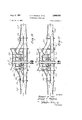
- FIGURE 10 is a diagrammatical view of the pump showing the manner in which fluid flows therethrough when the impellers are arranged in parallel;
- FIGURE 11 is a similar view to FIGURE 10 showing the flow diagram when the impellers are arranged in series;
- FIGURE 12 is a diagrammatical view showing the priming pump vacuum actuated transfer valve system
- FIGURE 13 is a diagrammatic view showing the manner in which the electric shift operating mechanism may operate
- FIGURE 14 is a diagrammatioal view showing the manner in which the power operated discharge valves may be operated.
- FIGURE 15 is a sectional view through a portion of the pump housing.
- the pump includes a main.
- This casting includes an intake manifold portion 11, a second intake manifold portion 12 and a discharge manifold portion 13 which are generally parallel and have their axes on a substantially horizontally common plane.
- the discharge manifold 13 is curved upwardly at its center portion to pass over the impeller shaft and to form a connection between the ends of this manifold which are on the same plane as the intake manifolds 11 and 12.
- the main casting is provided with an impeller cover casting 14 which is 'bolted or otherwise connected thereto along a parting line which extends on a horizontal plane through the axis of the impeller shaft 15.
- the main casting and the cover section 14. are shaped to provide volutes 16 and 17 in parallel spaced relation separated by a partition Wall 19.
- Center sealing member 20 is provided inwardly of the partition wall 19 to form a seal about the shaft 15 and to form a continuation of the partition wall 19.
- Impellers 21 and 22 are mounted upon the shaft 15 within the volutes 16 and 17.
- These impellers may be of any desired shape having intake ends 23 and 24 communicating with the intake manifolds 11 and 12, respectively. These intake ends work with a running fit with outer sealing rings 25 and 26 and inner sealing hubs 27 and 29, respectively, which are also mounted about the impeller shaft 15.
- the casing 10 and the cover 14 extend about the shaft 15 but in spaced relation thereto to form a stufiing box at each end of the housing, one such stufiing box being indicated at 30 and the other being indicated at 32.
- Lantern rings 33 and 34 are integral with the inner sealing members 27 and 29 and packing rings 35 and 36 are positioned outwardly of the lantern rings.
- a packing gland 37 is provided against the sealing rings 35 and a similar packing gland 39 is provided against the packing rings 36 to form a tight seal about the shaft 15.
- Each end of the pump housing is provided with an outboard support, these supports being indicated at 40 and 41 and having circular apertures 42 and 43 therein concentric With the shaft 15.
- a bearing support 44 is bolted or otherwise secured in one such aperture 43, this hearing support including a peripheral flange 45 and a cup-shaped closure 46 integral therewith and designed to enclose an end of the shaft 15.
- a bearing 47 is supported by the bearing support 44 and encircles the small diameter end portion 49 of the impeller shaft 15 to form a bearing therefor.
- the bearing support 44 may fit either in the aperture 43 at one end of the housing or the aperture 42, at the opposite end thereof. This arrangement is made so that the transmission housing, which will be later described, may be located on either side of the pump housing.
- a passage 48 extends through a portion of the volute cover 14 into the volute chamber at a point subject to fluid pressure from the volute. This passage communi cates with an angular passage 49 extending through the cover 14 to communicate with the stufiing box 30 in the area of the lantern ring 33.
- the passage 48 is alsd connected by suitable fittings 50 and 51 connected by a conduit 52 to a passage 53 through the volute cover 14 to communicate with the stuffing box '32 in the area of the lantern ring 34.
- impeller 21 is the first stage impeller and discharge pressure therefrom may communicate with the stufling box 30' to deliver water thereto to lubricate the joint. Due to the fact that the intake 11 is subject to partial vacuum in operation of the pump there is a tendency to draw air through the stuffing box 30 from outer atmosphere and the passages mentioned permit liquid under pressure to act as a sealing lubricant.
- the other connection including the fittings 5t and 51,
- conduit 52 and the passage 53 act to similarly lubricate the stuffing box 32 when the impeller discharges are connected in parallel.
- the pressure in the area of the lantern ring balances with pressure in the intake manifold 12.
- the transmission housing is best shown in FIGURE 7 of the drawings. It includes a hollow body portion which is elongated in a vertical direction and includes means for supporting three shafts in parallel relation.
- the first shaft comprises the projecting end of the impeller shaft 15.
- An idler shaft 54 is supported in parallel relation to the impeller shaft 15.
- a drive shaft 55 and an aligned driven shaft 56 are supported in parallel relation to the first mentioned shafts.
- a bearing support 57 encircles the projecting end of the impeller shaft 15 and supports a pair of spaced bearings 59 and 60 having a pinion 61 secured on the shaft 15 therebetween.
- the end of the bearing support 57 extends into the aperture 42 in the outboard support 40.
- This bearing support 57 fits between the body portion 62 of the transmission housing and the removable top portion 63 thereof.
- This top portion 63 is connected to the body portion 62 of the housing along a horizontal parting line on a plane through the axis of the shaft 15.
- Aligned apertures 64 and 65 are provided in the gear housing 62 for accommodation of bearings 66 and 67 encircling the idler shaft 54.
- Cover plates 69 and 70 overlie the apertures 64 and 65 to close the ends thereof.
- a closure plate 71 also closes the outer side of the bearing support 57 and a seal 72 encircles the shaft 15 inwardly of the bearing 59 to form a closure for the portion of the gear housing through which the shaft 15 extends.
- An idler gear 73 is mounted upon the shaft 54 to mesh with the pinion 61 and also with the gear 74.
- This gear 74 is mounted upon a sleeve or hub 75 rotatably supported for pivotal movement about the drive shaft 55.
- Bearings 76 are interposed between the drive shaft 55 and the hub 75 so that the two parts may be freely rotatable.
- the drive shaft 55 extends through an aperture 77 in a closure plate 79 secured to close the opening 80 in one side of the transmission housing.
- a bearing 81 is supported by the closure 79 to support one end of the shaft 55.
- a closure plate 82 is designed to close an opening 83 in the housing 62 opposite the aperture 80.
- the closure plate 82 includes a cup-shaped projection 84 which supports spaced bearings 85 which rotatably support the shaft 56.
- the shaft 56 extends through an aperture 86 and a seal 87 is provided for closing the housing at this point.
- the end of the shaft 56 is provided with a peripheral flange 89 connecting the shaft with an externally splined sleeve 90.
- the shaft 55 is provided with a splined or toothed end 91 of the same diameter as the sleeve 90.
- the hub 75 is likewise toothed or splined at 92.
- An internally splined sleeve '93 is slidable over the gear or splined part 91 and is selectively engageable with either the sleeve 96 or the end 92' of hub 75.
- this sleeve 93 When this sleeve 93 is moved to the left from the position shown, it may rotatably connect the members 91 and 92 to rotate the hub 75 in unison with the drive shaft 55. Rotation of the gear 74 on the hub 75' acts through the idler gear 73 and the pinion 61 to rotate the impeller shaft 15. To hold the shafts 55 and 56 in axial alignment, the reduced diameter end 94 of the drive shaft 55 is supported by a bearing 95 within the externally splined sleeve 90.
- the hub 75 also supports a gear 96 for rotation therewith.
- This gear 96 meshes with a gear 97 mounted upon a shaft 99 which is laterally spaced from the gear 96.
- the transmission housing 62 is provided with an opening 100 therein which is normally closed by a closure plate 101 forming the mounting plate of a priming pump housing 102.
- the priming pump housing includes a pair of spaced plates 103 and 104 which are connected by a pump chamber forming ring 105.
- the plates 103 and 104 are provided with opposed bosses 106 and 107 designed to accommodate bearing sleeves 109 and 110 to support a pump rotor shaft 111.
- a pump rotor 112 on the shaft 111 is in mesh with a cooperable rotor 113 on a parallel shaft which is an extension of the shaft 99.
- This shaft 99 is supported by a bearing sleeve 114 in a boss 115 in the plate 104 and a similar sleeve 116 in the mounting plate 101.
- the shaft 99 is provided with a reduced diameter end 117 extending through a bearing 119 inwardly of the gear 97.
- Alternate clutch plates of the disc clutch 120 are connected to a hub 121 on the gear 97 and the remaining plates are connected to the shaft 99.
- a sleeve 122 having a peripheral groove 123 therein is provided to apply pressure against the plates 120 to cause the shaft 99 to rotate in unison with the gear 97 when it is so desired.
- a shifting fork 124 is pivoted at 125 to a fixed support 126 and includes rollers 127 engageable in the groove 123 of the sleeve 122.
- the end of the shifting fork opposite the pivotal connection 125 is pivoted at 129 to an operating rod 130 which extends through an aperture 134 in the plate 101. Means later described in detail are provided for actuating the operating rod 130.
- the clutch 120 is normally held in operative position by a spring 135 encircling the operating rod 130.
- FIGURES 8 and 9 also indicate the manner in which the transmission is shifted.
- the sleeve 93 which is splined to selectively engage the drive shaft either with the driven shaft or the pump impeller shaft is externally grooved as indicated at 136 to accommodate the shoes 137 of a shifting fork 139.
- the shifting fork 139 is connected to a shaft 140 which extends through an aperture 141 in the transmission housing. Pivotal movement of the shaft 140 acts to slide the sleeve 93 to a selected position.
- the transmission may be secured to either side of the centrifugal pump during the assembly thereof.
- the pump is so constructed that the body of the pump may be inverted where it is desired.
- the supporting frame members are indicated at 142 1n FIG- URE 2 of the drawings and it will be noted that the drive shaft is in this arrangement slightly below the lower edges of these frame members.
- FIGURE 5 shows these same frame members but shows the body of the pump in inverted position.
- the axis of the drive shaft is considerably above the lower edges of the frame members 142.
- the distance between the tops of the frame members and the axis of the drive shaft is approximately cut in two by the inversion of the pump body.
- the body of the pump is provided at opposite ends with attachment flanges 143 and 144 which define the ends of the intake manifold passages 11 and 12 as well as the discharge passage 13.
- a generally Y-shaped section 145 and 145 is connected to each end of the pump body, one flange 146 of this casting being bolted or otherwise secured against a corresponding flange 143 or 144.
- Each of the Y-shaped castings 145 and 145 is designed to connect the ends of the intake passages 11 and 12 to a common passage.
- Each of the castings 145 and 145 is provided with an end flange 147 which is bolted or otherwise aflixed to a corresponding flange 149 of an end section 150 of the mtake housing.
- the outer extremities of the sections 150 are threaded at 151 for connection with a conduit leading to the supply source.
- a cap 152 is shown closing each end of the intake manifold structure, it being understood that one such cap is removed for connection with the suction conduit.
- the flanges 143 and 144 are also bolted or otherwise connected to discharge manifold castings 153 and 153, respectively.
- the discharge manifold 153 is of Y-shape with each passage end being flanged as indicated at 154.
- Discharge valves 155 are bolted or otherwise connected to the flanges 154, these valves being provided with operating handles 156 by means of which the valves may be individually operated.
- the handles 156 may also be automatically operated by remote control as will be later described in detail.
- the ends of the pump sections are similarly constructed so that the entire body portion of the pump may be inverted. If a considerable distance is desired between the upper surface of the frame members 142 and the drive shaft 55, the main pump housing 10 with its cover portion 14 are mounted as shown in FIGURE 1 of the drawings. On the other hand, if a lesser vertical distance between the upper ends of the frame members 142 and the drive shaft 55 is desired, these two parts 10 and 14 with the structure carried thereby are inverted and reversed end to end.
- the axis of the impeller shaft which is at the elevation indicated by the numeral 157, is even with the upper surfaces of the intake manifolds while the center line 157 is even with the lower surfaces of the intake manifolds when the pump is mounted as is shown in FIGURE 2.
- the castings 145 and 145' are provided with mounting pads 159 and 159 forming a part thereof. These pads 159 and 159 are designed to rest upon the frame members 142 in either position of the pump to support the same.
- the discharge casting 153 is provided with a circular flange 160 at its end which is secured to the flange 143 with bolts 161. These bolts are evenly spaced about the center of the flange 160. Accordingly, the angular position of casting 153 can be varied if desired. In the particular arrangement illustrated, the discharge valves 155 are on the same horizontal plane. If preferred, the casting 153 may be attached in a different angular relation so that the two valves 155 at this end of the pump may be one above the other.
- the discharge casting 153' is provided at its inner end with a flange 160' which may be bolted to the flange 144 by bolts 161.
- This casting 153' is also of Y-formation, one branch thereof being connected to a discharge valve 155.
- the other branch 158 of the Y forms a part of a by-pass to the intake housing end section 150', this by-pass including a relief valve which will be later described in detail.
- FIGURES 10 and 11 of the drawings show the flow through the main pump section as it would appear in plane with the pump mounted as in FIGURES 4 through 6 or as it would appear from below the pump as it would appear mounted as in FIGURES 1 through 3.
- the diagram also shows the flow as though both of the suction passages and both ends of the outlet or discharge valves were open.
- the fluid When the pump is to operate with the volutes in parallel, the fluid enters the intake manifold structure and flows through the manifolds 11 and 12 to the intake of the volutes.
- the first stage impeller 21 directs the flow through the volute 16 to a transverse passage 162 which leads to the transfer valve 163. With the transfer valve in the position shown in FIGURE 10, the discharge from the transfer valve is conducted to a passage 164 leading to the discharge manifold 13. From the manifold 13 the 7 fluid may flow in either direction through the desired casting or castings 153 and 153' as previously described.
- the discharge from the second stage impeller 22 flows through a passage 165 to a transverse passage 166 communicating with the discharge manifold 13.
- the suction side of both impellers are in communication with the water supply source through the manifolds 11 and 12.
- the transfer valve 163 When the pump is in series, as is indicated in FIGURE 11 of the drawings, the transfer valve 163 is turned to its second extreme position. In this position the fluid enters the manifold 11 and passes into the impeller 21. The fluid flows through the volute 16 and into the transverse passage 162. The fluid flows through the transfer valve 163 and into the intake manifold 12 leading to the second stage impeller 22. This causes an increase in pressure in the manifold 12 and in the adjoining intake passages 167 and 169 in the Y-shaped castings 145. This unbalanced pressure causes the flap valves or check valves 170 and 171 to swing into closed position so that the discharge from the first impeller 21 flows into the intake of the second impeller 22. The discharge from the second impeller passes through the passage 165 to the transverse passage 166 communicating with the discharge manifold 13.
- a relief valve is provided in a by-pass line between the intake and casting 150 and, the branch 158 of the discharge casting 153. This is shown. in general in FIG- URE 4 of the drawings and is designated generally by the numeral 172. The valve is more completely shown in section in FIGURE 15.
- the by-pass includes a T-shaped casting having an externally flanged passage portion 173 bolted to the intake end casting 150' and communicating with the interior thereof.
- One end 17 4 of the cross member portion of the T-shaped casting is externally flanged for connection with the branch 158 of the discharge casting 153'.
- the other end 175 of the valve casting slidably supports a hollow piston valve 176.
- An end closure plate 177 on the casting end 175 supports a guide sleeve 178 extending into the piston 176 to guide the movement thereof.
- a spring 179 interposed between the end of the hollow piston valve and the closure plate 177 urges the piston valve against its valve seat 180 at the entrance of the valve casting end 174 connected to the discharge casting 153'.
- FIGURE 15 A relief valve control illustrated in general by numeral 181 is shown in FIGURE 15. This control 181 is actually mounted on the pump control. panel. However, to describe the operation thereof, the connecting lines have been shortened so that both parts can be conveniently shown in the same figure of the drawings.
- the valve control 181 includes a sleeve 301 connected at one end to an end plate 302 and at its opposite end to a diaphragm valve housing 303.
- This housing includes an axial diaphragm chamber 304 across which a diaphragm 305 extends.
- a valve rod 306 extends through the diaphragm and is secured thereto by shoulder members 307 and 309 clamped together by a clamping nut 310.
- the valve rod 306 forms in effect a movable valve engageable with a valve seat 311 against which the rod engages.
- the valve housing 303 includes three ports, the first of which is designated by the numeral 312 and which is normally connected by a conduit 313 to the four way valve 314 having a connection 315 leading to the pump discharge 13 at any suitable point.
- a second port 316 is connected through the valve 314 to a connection 317 leading to the relief valve chamber between the valve piston 176 and the end closure plate 177.
- a drain line 319 is normally closed by a valve 320.
- the third valve port 321 in valve housing 303 is connected through a conduit 322 to the pump intake.
- the port 312 communicates with the diaphragm chamber 304 to exert a pressure against the diaphragm 305. This, port 312 also communicates with the second port 316, and through valve 314 and conduit 317 to the interior of the relief valve chamber. Thus discharge pressure is exerted both against the relatively small diameter of the valve piston end 323 and against the opposite larger diameter valve piston end 324, this last force acting in the same direction as the spring 179 to close the valve.
- a spring 325 is arranged to oppose the force against the diaphragm 305.
- a rotatable shaft 326 extends through the end plate 302 and is provided on its outer end with a handle or crank 327 by means of which it may be rotated. Rotation of the shaft 326 acts to move a nut 329 toward or away from the diaphragm.
- the spring 325 is, interposed between the nut 329 and the clamping member 309. By this means the compression of spring 325 may be regulated, increasing or decreasing the force of the spring upon the diaphragm.
- the spring 325 When the pump is in operation, the spring 325 normally holds the valve rod 306 in engagement with the valve seat 311. The discharge pressure is thus exerted on opposite sides of the relief valve piston 176, holding this valve closed. If an abnormal pressure builds up in the pump discharge, the spring 325 is compressed, moving the valve rod 306 from its seat 311. Port 316 is then connected to intake pressure, relieving the pressure against the end 324 of the valve piston 176 and allowing pressure on the opposite end 323 of the valve to open this valve.
- the connection between the ports 312 and 316 comprises a narrow ring-shaped passage encircling the valve rod 306, so that the fluid under pressure may escape through the port 321 faster than it can enter from port 312.
- a spring urged ball 330 is engageable in spaced notches 331 in a collar 332 on the shaft 326 to hold the shaft in adjusted position.
- valve 314 may be rotated to connect conduits 315 and 317, and also conduct 313 to the conduit leading to port 316.
- discharge pressure may be exerted directly against piston 324 regardless of movement of rod 306, and the relief valve rendered inoperative.
- FIGURE 13 of the drawings The circuit for operating the electric shift unit is diagrammatically illustrated in FIGURE 13 of the drawings.
- This apparatus comprises a motor driven device indicated in general by the numeral 132 and mounted upon the gear case housing 62 in the manner illustrated in FIGURE 8 of the drawings.
- the transmission is shifted by means of a shifting fork 139 mounted upon a shaft 140.
- the shaft 140 is equipped with a lever arm 183 pinned thereto at 183' by means of which the shaft may be manually rotated to shift the gears.
- This fork 139 is provided with an extension 184' which extends through an opening in the rear of the gear case and is slotted at its extremity as indicated at 184.
- the motor driven device 182 includes a housing which is bolted to close the gear case opening.
- This motor driven shifting device includes a driven pin 185 engaged in the notch 184 to rock the shift lever 139, thereby moving the clutch into position to connect the engine either to the pump or to the truck drive wheels.
- the shifting unit is reversible, and moves the shifting lever from one extreme position in which the truck drive wheels are connected to the engine to its other extreme position in which the pump is connected to the truck engine. Between these positions, the clutch is disengaged.
- the shifting unit is reversible, and one terminal of the reversible motor is grounded at 136.
- the truck battery 187 is grounded at 189, and the other battery terminal is connected by a conductor 190 through the ignition switch 191 and the circuit breaker 192 to the armature 193 of a single pole double throw switch.
- the two switch contacts are connected by conductors 194 and 195 to the two motor terminals of the unit 182. When the circuit is closed through one of these conductors, the unit 182, and shift lever 139, are moved in one direction.
- FIGURE 4 of the drawings is disclosed diagrammatically an actuating device 201 which is used to operate the transfer valve.
- the transfer valve is provided with an operating shaft 202 which projects from the pump housing and is provided with an operating lever 203 by means of which the transfer valve may be rotated.
- the device 201 comprises an expandable and contractable element which is pivotally connected at 204 to the pump housing and pivotally connected at 205 to the transfer valve lever arm 203.
- the transfer valve Upon expansion of the device 201 or elongation thereof, the transfer valve is operated in a counter-clockwise direction to its other extreme position.
- the device may operate in both directions or is reversible.
- FIGURE 12 of the drawings diagrammatically illustrates the operation of this apparatus.
- This figure illustrates the vacuum actuated device 201 which is shown as including a cylinder 206 having a piston 207 therein which is reciprocable between two extreme positions.
- a conduit 209 connects the valve element of the device 201 through a check valve 210 with the intake side of the priming pump 102.
- a source of partial vacuum is provided.
- the priming pump closure plate 104 may include as an extension of the boss 107 a mounting flange 211 to which may be secured an electric motor 212.
- the shaft 213 may be coupled to the rotor shaft 111 by a suitable coupling member 214.
- This motor 212 may be operated to actuate the priming pump when desired so that this pump may be selectively operated either electrically or mechanically through the gear train and transmission.
- the intake of the priming pump 102 is connected by a portion of the conduit 209 and a connecting conduit 213 to a priming valve 214.
- This priming valve 214 includes a connection 215 communicating with the pump discharge. It also includes connections 216 leading to the suction eyes of the first and second stage of the pump.
- the valve 214 is actuated by a solenoid 217 which is arranged in a circuit which will be later described.
- the pump When the pump is to be primed, air is drawn from the suction eyes of the impellers through the passages 216, the valve 214 and the conduits 213 and 209 to the intake of the priming pump 102.
- the discharge of the priming pump is indicated at 219 and leads to atmosphere.
- the valve 214 is operated by an internal spring to close the inlet conduit 213 when pressure of Water is available in the pump discharge and the conduit 215 by releasing push button switch 229.
- the valve 214 is closed to prevent fluid under pressure from by-passing to the suction eyes and leaking out to atmosphere through priming pump 102.
- the check valve 210 permits air to be drawn from the priming pump 102 to the valve 220 of the device 201 but will not permit a reverse flow.
- the switch 229 When it is desired to prime the pump through the use of the priming motor 212, the switch 229 is closed. As was previously described, one terminal 189 of the vehicle battery 187 is grounded, While the other leads through the ignition switch 191 to the circuit breaker 192. A connection 221 leads from the battery terminal 191 to a relay contact 222 which is normally in spaced relation to a cooperable contact 223. The contact 223 is connected by a conductor 224 to one terminal of the priming pump motor 212. The other terminal of this motor is grounded as indicated at 225.
- the relay coil 231 is connected by a conductor 226 to one terminal 227 of a double pole single throw switch 229. When this switch is closed a circuit is closed to conductor 230 leading to the circuit breaker 192. Thus when the switch 229 is closed a circuit is closed from the battery terminal 190 through the circuit breaker 192, conductor 230, terminal 227, conductor 226, to one terminal of a relay coil 231 which controls the movement of the armature 232 supporting contact 223. The other terminal of the coil 231 is grounded at 233. As a result, current will flow from the battery terminal through conductor 221, contacts 222 and 223, and conductor 224 to the motor to energize this motor.
- the switch 229 is provided with a grounded terminal 234 connected to a switch arm engageable with a contact 235. This contact is connected to one terminal of a relay coil 236 to ground this side of the coil when the switch 229 is closed.
- the other relay coil terminal is connected by a conductor 237 to the conductor 230 leading to the ungrounded side of the battery; thus completing the circuit and energizing the coil 236.
- the coil 236 attracts an armature 237 and draws this armature into engagement with a switch contact 239 connected by conductors 237 and 230 to the ungrounded side of the battery.
- the armature 237 is connected by conductor 240 to the solenoid 217, the second terminal of which is grounded at 241.
- the solenoid 217 is also actuated to operate the valve 214.
- the inlet 209 of the priming pump 102 is connected by conduits 213, 215 and 216 to the interior of the centrifugal pump acting to evacuate air therefrom and to draw water from a suitable source into the pump intake.
- the transfer valve operating mechanism is indicated in FIGURE 12 of the drawings and includes a double pole double throw switch 242 with momentary contact positions and a center off position.
- the switch arms of the switch 242 are electrically connected by conductor 243 with the conductor 230 leading to the ungrounded side of the battery 187. Accordingly, when the transfer valve is operated (normally at a time when the pump is in operation) one of the switch blades is in contact either with the switch terminal 244 or the switch terminal 245, both of which are connected by the conductor 246 to the conductor 226 which energizes the relay coil 231 and starts the priming pump in operation.
- the other blade of the switch 242 is selectively connected to a switch com tact 247 or a contact 249.
- Switch 252 and 255 are of the single pole double throw type including one normally open terminal and one normally closed terminal.
- the normally closed terminal 256 of switch 252 is connected by conductor 257 to one terminal of a solenoid 220 which is double acting and which is grounded at 259.
- the normally closed terminal 260 of switch 255 is connected by a conductor 261 to the opposed coil of the solenoid 220.
- the normally open terminal 262 of switch 252 is connected by a conductor 263 to one terminal of an indicating light 264, the other terminal of which is grounded at 265.
- the normally open terminal 266 of switch 255 is connected by a conductor 267 to a second signal light 269, the other terminal of which is grounded at 265.
- the switches 252 and 255 are actuated by the valve arm 203 which controls the transfer valve.
- the common terminal 251 will be connected to terminal 262 connected by conductor 263 to the indicating light 264 which is illuminated to indicate that the transfer valve is in position for parallel operation.
- switch 255 is not in circuit, the switch 242 being in position for parallel operation.
- the switch 242 is moved into a position where. the contacts 245 and- 249 are connected to the ungrounded side of the battery.
- This action moves the piston 207 to the right until the arm 203 engages the operating button 270 of switch 255, breaking the circuit to the solenoid valve 220 and closing the circuit through terminal 266 to the conductor 267 acting to illuminate the indicating light 269 to show that the transfer valve is in position for series operation.
- the switch 242 may then be opened until further operation is required.
- the switch 242 In transferring the pump to parallel operation, the switch 242 is returned to its left hand position operating to actuate the solenoid valve 220 in a manner to evacuate air from the left hand end of cylinder 291, moving the piston 207 to the left until it reaches its opposite extreme position.
- Valve arm 156 actuates the valve 155 between its two extreme positions.
- the arm 156 is shown in full lines in open position and in dotted lines in closed position.
- a linear electric actuator 271 is pivotally attached at 272 to a suitably fixed bracket 273 secured to the body of the valve in a suitable manner.
- the actuator 271 is provided with a motor 274 capable of swinging the arm 156 between its two extreme positions.
- the motor 274 is reversible and is grounded at 275.
- the motor 274 is controlled by action of a relay 276.
- the ignition switch is connected by connector 277 through a circuit breaker 278 to the relay armature 279.
- This armature 279 is selectively engaged with conductor 280 or conductor 281 leading to the actuator motor 274.
- the actuator motor moves in one direction to open the valve 155.
- the armature engages conductor 282 the motor moves in the opposite direction to close valve 155.
- Push but-ton switches 282 and 283 have one terminal grounded at 284.
- the other terminal of switch 282 is connected through conductor 285 to relay coil 286, the other terminal of which is connected to the hot wire 277 leading through the ignition switch to the battery 187.
- push button switch 282 when closed, draws the relay armature into contact with conductor 280 to open valve 155.
- the second terminal of switch 283 is connected through conductor 287 to relay coil 288, the other terminal of which is connected to the hot wire 277.
- switch 283 When switch 283 is closed, the relay armature 279 engages conductor 281, and the actuator motor acts to close valve 155.
- Limit switches may be employed for breaking the circuit when the extreme positions of the arm 156 are reached.
- An indicator 291 of the type often used to indicate a gasoline level in gasoline tanks and the like is employed for indicating the position of each arm 156.
- the details of the indicator are not illustrated.
- a circuit controlling device 292 which may be in the form of a rheostat 289 actuated by a rheostat arm 293 pivotal with the arm 156. Pivotal movement of the arm 293 varies the current through the control device 292.
- the indicator 291 includes an indicator arm 295 which is pivotally supported and the position of which is regulated by a magnetic element 296.
- One terminal of the magnetic device 296 is connected by a conductor 297 to the vehicle battery 187 while the other terminal is connected by a. conductor 299 to the operating device 292 12 which is grounded at 360.
- the pointer or needle 295 Will move a corresponding distance so that the position of each of the arms may be noted.
- the present invention involves a centrifugal pump having a body portion which may be supported in either of two positions, one of which is inverted with respect to the other.
- the pump is provided with a transfer valve which may be controlled by a vacuum cylinder connected to the priming pump as a source of supply of partial vacuum.
- a transfer valve which may be controlled by a vacuum cylinder connected to the priming pump as a source of supply of partial vacuum.
- the transmission may be actuated by remote control from a drive position to a pump engaged position so that a minimum of time will be required to connect either the vehicle drive wheels or the pump to the vehicle engine.
- the discharge valves may be operated by remote control, thus permitting virtually every operation of the apparatus to be controlled from a single control panel. Thus substantial time may be saved in the operation of the apparatus resulting in higher efficiency of the equipment.
- a centrifugal pump including a central body portion including a housing, a pair of spaced impeller chambers forming a part of said housing, an outlet manifold forming a part of said housing, a pair of intake manifolds forming a part of the housing, attachment flanges at opposite ends of said body, impellers in said housing, a shaft supporting said impellers, means supporting said shaft on a horizontal position in said housing, the intake manifolds and outlet manifold being positioned on a substantially horizontal plane and said shaft having its axis on a horizontal plane, vertically spaced relative to said first named horizontal plane, manifold extensions, spaced supporting means supporting said manifold extensions, connecting means detachably connecting said manifold extensions to said attachment flanges, said connecting means being so located that said attachment flanges are attachable to one set of manifold extensions when said housing is upright and to the opposite set of manifold extensions when said housing is inverted, whereby the elevation of the impeller shaft may be varied by inverting the
- a centrifugal pump including a central body portion including a housing, a pair of spaced impeller chambers forming a part of said housing, an outlet manifold forming a part of said housing, a pair of intake manifolds forming a part of the housing, attachment flanges at opposite ends of said body, impellers in said housing, a shaft supporting said impellers, means supporting said shaft on a horizontal position in said housing, the intake manifolds and outlet manifold being positioned on a substantially horizontal plane and said shaft having its axis on a horizontal plane vertically spaced from said first named horizontm plane, said attachment flanges encircling said intake and outlet manifolds, an outlet manifold means detachably connecting one of said outlet manifolds to each attachment flange, said connecting means being located for connection with one flange in upright position of said housing and with the other flange in inverted position of said housing, and means connected to said outlet manifold extensions to support the same with said housing therebet
Landscapes
- Engineering & Computer Science (AREA)
- Health & Medical Sciences (AREA)
- Public Health (AREA)
- Business, Economics & Management (AREA)
- Emergency Management (AREA)
- Mechanical Engineering (AREA)
- General Engineering & Computer Science (AREA)
- Structures Of Non-Positive Displacement Pumps (AREA)
Description
Aug. 8, 1961 D. F. THOMAS EI'AL 2,995,092
CENTRIFUGAL FIRE PUMP Filed Feb. 2. 1956 7 Sheets-Sheet 1 --/4:? f 2 y SEE-EA INVENTORS 3 Robe/f ,4. H/'// 157. zaz Dar/b F Thomas ATTORNEY ,&
Aug. 8, 1961 D. F. THOMAS ET AL 2,995,092
CENTRIFVUGAL FIRE PUMP Filed Feb. 2, 1956 7 Sheets-Sheet 2 INVENTORS Four ,4. 1907/ 5'7 6 Dal I'd F Thomas ATTORNEY 7 Sheets-Sheet 3 Filed Feb. 2, 1956 1NVENTOR3 Aug. 8, 1961 D. F. THOMAS EI'AL 2,995,092
CENTRIFUGAL FIRE PUMP Filed Feb. 2, 1956 '7 Sheets-Sheet 4 1 N VE NTOR Robe/"f A /1/'// 1,25 Dar/d F Thomas ATTORNEY Aug. 8, 1961 D. F. THOMAS ETAL CENTRIFUGAL FIRE PUMP '7 Sheets-Sheet 5 Filed Feb. 2, 1956 INVENTOR Qlnv Dan Q: F. Thomas BY WYLEAO ql ORNEY Aug. 8, 1961 D. F. THOMAS ET AL CENTRIFUGAL FIRE PUMP '7 Sheets-Sheet 6 Filed Feb. 2, 1956 NNN I WQMW INVENTOR 2,995,092 CENTUGAL FIRE PUll/IP David F. Thomas, West St. Paul, and Robert A. Hill, Minneapolis, Minn, assignors to Waterous Company, St. Paul, Minn, a corporation of Minnesota Filed Feb. 2, 1956, Ser. No. 562,959 8 Claims. (Cl. 103106) This invention relates to an improvement in centrifugal fire pumps and deals particularly with a type of pump which is adaptable to different installations and which may be actuated by remote control.
In the manufacture of pumps used on fire trucks and the like, it has been usual practice to produce a particular pump for a particular installation. For example, such pumps are usually designed to rest upon the frame of the truck and to be driven by a power shaft located at a particular vertical distance from the top of the supporting frame. With modernization of fire trucks, the elevation of the power drive shaft has in some instances been changed. In view of the tremendous cost involved in making patterns for pumps of this type, and in view of the tremendous cost in the pumps themselves, it is uneconomical to design an entirely new pump each time the location of the drive shaft is changed. Accordingly, an object of the present invention lies in the provision of a pump, the main portion of which is cast in one piece and in arranging the pump so that this main piece may be inverted if desired. By inverting the position of the main casting the height of the impeller shaft may be varied thereby permitting a different elevation in the drive shaft.
A feature of the present invention lies in the fact that the pump includes a main pump casting, intake manifold castings and discharge manifolds which may connect with the main casting either in upright position or inverted position. .As a result the major portions of the pump are identical regardless of the position of the main casting.
An added feature of the present invention resides in the specific arrangement of flow passages in the pump and the manner in which the fluid passes through the pump either when the impellers are arranged in series or in parallel. When the impellers are arranged in series, the discharge from the first stage flows to the intake of the second stage through a transfer valve. Check valves are provided which are automatically operated when the second stage intake is subjected to discharge pressure from the first stage. When the transfer valve is suitably operated, the discharge from both impellers communicate with a common discharge manifold.
A feature of the present invention lies in the provision of a pump having intake manifolds and discharge manifolds on a common horizontal plane. As a result when the main pump casting is inverted, the manifold portions externally of the main casting are in proper position for attachment to the main casting.
A further feature of the present invention resides in a novel method of operation of the transfer valve. The transfer valve may be actuated by a vacuum cylinder which is connected to the intake side of the priming pump. When the transfer valve is to be moved, the priming pump is actuated to provide a source of partial vacuum which is communicated to the vacuum cylinder for a length of time sufficient to move the transfer valve from one position to the other. When the transfer valve reaches its second position it automatically stops and remains in this new position until it is desired to return the valve to its first position.
A feature of the present invention resides in the provision of a power control for controlling the operation of the transfer valve mechanism. This control acts to operate the priming pump for the time necessary to move the control valve from one position to the other and tent 6 2,995,092 Patented Aug. 8, 1961 then to automatically stop the operation of this priming pump. In preferred form, indicator lights or other such means are provided for indicating the position of the transfer valve at a remote location so that the operator may at all times know immediately the position of this valve.
A feature of the present invention resides in the provision of a transfer valve vacuum operating means and in providing a constant supply of partial vacuum for operating this valve actuating means. The intake manifold of the internal combustion engine is the most common source of partial vacuum supply used on vacuum actuated devices. However, the vacuum source varies substantially depending upon whether the engine is operating under load or unloaded. By using the priming pump as a source of partial vacuum, the source may be constant.
A further feature of the present invention resides in the provision of a control device for shifting the transmission of the apparatus from a position in which the drive from the motor extends through the transmission to the vehicle wheels to a second position in which the motor drive operates the pump. This remote control means is usually electrically operated and permits remote control virtually instantaneously by the operator to minimize the time required for the pump to get in operation.
A further feature of the present invention resides in the provision of a remote control for operating one or more of the discharge valves of the pump. As a result the operator can control the entire operation of the pump from one predetermined position.
These and other objects and novel features of my invention will be more clearly and fully set forth in the following specification and claims.
In the drawings forming a part of the specification:
FIGURE 1 is a top plan view of the centrifugal pump showing the general arrangement of parts therein.
FIGURE 2 is a side elevational view of the same.
FIGURE 3 is an end elevational view of the same.
FIGURE 4 is a top plan view of the pump with the main pump section inverted.
FIGURE 5 is a side elevational view of the arrangement shown in FIGURE 4;
FIGURE 6 is an end elevational view of the pump shown in FIGURES 4 and 5;
FIGURE 7 is a sectional view through the pump shown in FIGURES 1 to 3, the position of the section being indicated by the line 77 of FIGURE 2;
FIGURE 8 is a horizontal section through the transmission and priming pump, the position of the section being indicated by the line 8-8 of FIGURE 3;
FIGURE 9 is a section through the priming pump, the position of the section being indicated by the line 9-9 of FIGURE 8;
FIGURE 10 is a diagrammatical view of the pump showing the manner in which fluid flows therethrough when the impellers are arranged in parallel;
FIGURE 11 is a similar view to FIGURE 10 showing the flow diagram when the impellers are arranged in series;
FIGURE 12. is a diagrammatical view showing the priming pump vacuum actuated transfer valve system;
FIGURE 13 is a diagrammatic view showing the manner in which the electric shift operating mechanism may operate;
FIGURE 14 is a diagrammatioal view showing the manner in which the power operated discharge valves may be operated; and
FIGURE 15 is a sectional view through a portion of the pump housing.
With reference now to FIGURES l, 2 and 3 of the drawings, it will be noted that the pump includes a main.
casting indicated in general by the numeral 10. This casting includes an intake manifold portion 11, a second intake manifold portion 12 and a discharge manifold portion 13 which are generally parallel and have their axes on a substantially horizontally common plane. As indicated in FIGURE 7 of the drawings, the discharge manifold 13 is curved upwardly at its center portion to pass over the impeller shaft and to form a connection between the ends of this manifold which are on the same plane as the intake manifolds 11 and 12.
The main casting is provided with an impeller cover casting 14 which is 'bolted or otherwise connected thereto along a parting line which extends on a horizontal plane through the axis of the impeller shaft 15. The main casting and the cover section 14. are shaped to provide volutes 16 and 17 in parallel spaced relation separated by a partition Wall 19. Center sealing member 20 is provided inwardly of the partition wall 19 to form a seal about the shaft 15 and to form a continuation of the partition wall 19. Impellers 21 and 22 are mounted upon the shaft 15 within the volutes 16 and 17. These impellers may be of any desired shape having intake ends 23 and 24 communicating with the intake manifolds 11 and 12, respectively. These intake ends work with a running fit with outer sealing rings 25 and 26 and inner sealing hubs 27 and 29, respectively, which are also mounted about the impeller shaft 15.
On either side of the intake manifolds 11 and 12, the casing 10 and the cover 14 extend about the shaft 15 but in spaced relation thereto to form a stufiing box at each end of the housing, one such stufiing box being indicated at 30 and the other being indicated at 32. Lantern rings 33 and 34 are integral with the inner sealing members 27 and 29 and packing rings 35 and 36 are positioned outwardly of the lantern rings. A packing gland 37 is provided against the sealing rings 35 and a similar packing gland 39 is provided against the packing rings 36 to form a tight seal about the shaft 15.
Each end of the pump housing is provided with an outboard support, these supports being indicated at 40 and 41 and having circular apertures 42 and 43 therein concentric With the shaft 15. A bearing support 44 is bolted or otherwise secured in one such aperture 43, this hearing support including a peripheral flange 45 and a cup-shaped closure 46 integral therewith and designed to enclose an end of the shaft 15. A bearing 47 is supported by the bearing support 44 and encircles the small diameter end portion 49 of the impeller shaft 15 to form a bearing therefor. It should be noted that the bearing support 44 may fit either in the aperture 43 at one end of the housing or the aperture 42, at the opposite end thereof. This arrangement is made so that the transmission housing, which will be later described, may be located on either side of the pump housing.
A passage 48 extends through a portion of the volute cover 14 into the volute chamber at a point subject to fluid pressure from the volute. This passage communi cates with an angular passage 49 extending through the cover 14 to communicate with the stufiing box 30 in the area of the lantern ring 33. The passage 48 is alsd connected by suitable fittings 50 and 51 connected by a conduit 52 to a passage 53 through the volute cover 14 to communicate with the stuffing box '32 in the area of the lantern ring 34.
The purpose of this arrangement will be evident when it is understood that the impeller 21 is the first stage impeller and discharge pressure therefrom may communicate with the stufling box 30' to deliver water thereto to lubricate the joint. Due to the fact that the intake 11 is subject to partial vacuum in operation of the pump there is a tendency to draw air through the stuffing box 30 from outer atmosphere and the passages mentioned permit liquid under pressure to act as a sealing lubricant. The other connection including the fittings 5t and 51,
the conduit 52 and the passage 53, act to similarly lubricate the stuffing box 32 when the impeller discharges are connected in parallel. When the impellers are connected in series, the pressure in the area of the lantern ring balances with pressure in the intake manifold 12.
The transmission housing is best shown in FIGURE 7 of the drawings. It includes a hollow body portion which is elongated in a vertical direction and includes means for supporting three shafts in parallel relation. The first shaft comprises the projecting end of the impeller shaft 15. An idler shaft 54 is supported in parallel relation to the impeller shaft 15. A drive shaft 55 and an aligned driven shaft 56 are supported in parallel relation to the first mentioned shafts.
A bearing support 57 encircles the projecting end of the impeller shaft 15 and supports a pair of spaced bearings 59 and 60 having a pinion 61 secured on the shaft 15 therebetween. The end of the bearing support 57 extends into the aperture 42 in the outboard support 40. This bearing support 57 fits between the body portion 62 of the transmission housing and the removable top portion 63 thereof. This top portion 63 is connected to the body portion 62 of the housing along a horizontal parting line on a plane through the axis of the shaft 15.
An idler gear 73 is mounted upon the shaft 54 to mesh with the pinion 61 and also with the gear 74. This gear 74 is mounted upon a sleeve or hub 75 rotatably supported for pivotal movement about the drive shaft 55. Bearings 76 are interposed between the drive shaft 55 and the hub 75 so that the two parts may be freely rotatable.
The drive shaft 55 extends through an aperture 77 in a closure plate 79 secured to close the opening 80 in one side of the transmission housing. A bearing 81 is supported by the closure 79 to support one end of the shaft 55. A closure plate 82 is designed to close an opening 83 in the housing 62 opposite the aperture 80. The closure plate 82 includes a cup-shaped projection 84 which supports spaced bearings 85 which rotatably support the shaft 56. The shaft 56 extends through an aperture 86 and a seal 87 is provided for closing the housing at this point.
The end of the shaft 56 is provided with a peripheral flange 89 connecting the shaft with an externally splined sleeve 90. The shaft 55 is provided with a splined or toothed end 91 of the same diameter as the sleeve 90. The hub 75 is likewise toothed or splined at 92. An internally splined sleeve '93 is slidable over the gear or splined part 91 and is selectively engageable with either the sleeve 96 or the end 92' of hub 75. As a result when the sleeve 93 is in the position shown in FIGURE 7, the drive gear 55 is rotatably connected to the driven shaft 56. When this sleeve 93 is moved to the left from the position shown, it may rotatably connect the members 91 and 92 to rotate the hub 75 in unison with the drive shaft 55. Rotation of the gear 74 on the hub 75' acts through the idler gear 73 and the pinion 61 to rotate the impeller shaft 15. To hold the shafts 55 and 56 in axial alignment, the reduced diameter end 94 of the drive shaft 55 is supported by a bearing 95 within the externally splined sleeve 90.
From an examination of FIGURES 7, 8 and 9 of the drawings it will be noted that the hub 75 also supports a gear 96 for rotation therewith. This gear 96 meshes with a gear 97 mounted upon a shaft 99 which is laterally spaced from the gear 96. The transmission housing 62 is provided with an opening 100 therein which is normally closed by a closure plate 101 forming the mounting plate of a priming pump housing 102. The priming pump housing includes a pair of spaced plates 103 and 104 which are connected by a pump chamber forming ring 105. The plates 103 and 104 are provided with opposed bosses 106 and 107 designed to accommodate bearing sleeves 109 and 110 to support a pump rotor shaft 111. A pump rotor 112 on the shaft 111 is in mesh with a cooperable rotor 113 on a parallel shaft which is an extension of the shaft 99. This shaft 99 is supported by a bearing sleeve 114 in a boss 115 in the plate 104 and a similar sleeve 116 in the mounting plate 101.
The shaft 99 is provided with a reduced diameter end 117 extending through a bearing 119 inwardly of the gear 97. Alternate clutch plates of the disc clutch 120 are connected to a hub 121 on the gear 97 and the remaining plates are connected to the shaft 99. A sleeve 122 having a peripheral groove 123 therein is provided to apply pressure against the plates 120 to cause the shaft 99 to rotate in unison with the gear 97 when it is so desired.
As is indicated in FIGURE 9 of the drawings, a shifting fork 124 is pivoted at 125 to a fixed support 126 and includes rollers 127 engageable in the groove 123 of the sleeve 122. The end of the shifting fork opposite the pivotal connection 125 is pivoted at 129 to an operating rod 130 which extends through an aperture 134 in the plate 101. Means later described in detail are provided for actuating the operating rod 130. The clutch 120 is normally held in operative position by a spring 135 encircling the operating rod 130.
FIGURES 8 and 9 also indicate the manner in which the transmission is shifted. The sleeve 93 which is splined to selectively engage the drive shaft either with the driven shaft or the pump impeller shaft is externally grooved as indicated at 136 to accommodate the shoes 137 of a shifting fork 139. The shifting fork 139 is connected to a shaft 140 which extends through an aperture 141 in the transmission housing. Pivotal movement of the shaft 140 acts to slide the sleeve 93 to a selected position.
From FIGURE 7 of the drawings, it will be evident that the transmission may be secured to either side of the centrifugal pump during the assembly thereof. It is 1mportant to note that the pump is so constructed that the body of the pump may be inverted where it is desired. This provides a variation in the distance between the supporting portion of the vehicle frame and the aligned drive shaft and driven shaft. For the purpose of example, the supporting frame members are indicated at 142 1n FIG- URE 2 of the drawings and it will be noted that the drive shaft is in this arrangement slightly below the lower edges of these frame members. FIGURE 5 shows these same frame members but shows the body of the pump in inverted position. It will be noted that in this case the axis of the drive shaft is considerably above the lower edges of the frame members 142. In actual practice, the distance between the tops of the frame members and the axis of the drive shaft is approximately cut in two by the inversion of the pump body.
With reference now to FIGURES 1, 2 and 3 of the drawings, it will be noted that the body of the pump is provided at opposite ends with attachment flanges 143 and 144 which define the ends of the intake manifold passages 11 and 12 as well as the discharge passage 13. A generally Y-shaped section 145 and 145 is connected to each end of the pump body, one flange 146 of this casting being bolted or otherwise secured against a corresponding flange 143 or 144. Each of the Y-shaped castings 145 and 145 is designed to connect the ends of the intake passages 11 and 12 to a common passage. Each of the castings 145 and 145 is provided with an end flange 147 which is bolted or otherwise aflixed to a corresponding flange 149 of an end section 150 of the mtake housing. The outer extremities of the sections 150 are threaded at 151 for connection with a conduit leading to the supply source. A cap 152 is shown closing each end of the intake manifold structure, it being understood that one such cap is removed for connection with the suction conduit.
The flanges 143 and 144 are also bolted or otherwise connected to discharge manifold castings 153 and 153, respectively. The discharge manifold 153 is of Y-shape with each passage end being flanged as indicated at 154. Discharge valves 155 are bolted or otherwise connected to the flanges 154, these valves being provided with operating handles 156 by means of which the valves may be individually operated. The handles 156 may also be automatically operated by remote control as will be later described in detail.
From the foregoing description it will be seen that the ends of the pump sections are similarly constructed so that the entire body portion of the pump may be inverted. If a considerable distance is desired between the upper surface of the frame members 142 and the drive shaft 55, the main pump housing 10 with its cover portion 14 are mounted as shown in FIGURE 1 of the drawings. On the other hand, if a lesser vertical distance between the upper ends of the frame members 142 and the drive shaft 55 is desired, these two parts 10 and 14 with the structure carried thereby are inverted and reversed end to end. In this relation the axis of the impeller shaft, which is at the elevation indicated by the numeral 157, is even with the upper surfaces of the intake manifolds while the center line 157 is even with the lower surfaces of the intake manifolds when the pump is mounted as is shown in FIGURE 2.
As is indicated in FIGURES 2 and 5 of the drawings, the castings 145 and 145' are provided with mounting pads 159 and 159 forming a part thereof. These pads 159 and 159 are designed to rest upon the frame members 142 in either position of the pump to support the same.
The discharge casting 153 is provided with a circular flange 160 at its end which is secured to the flange 143 with bolts 161. These bolts are evenly spaced about the center of the flange 160. Accordingly, the angular position of casting 153 can be varied if desired. In the particular arrangement illustrated, the discharge valves 155 are on the same horizontal plane. If preferred, the casting 153 may be attached in a different angular relation so that the two valves 155 at this end of the pump may be one above the other.
The discharge casting 153' is provided at its inner end with a flange 160' which may be bolted to the flange 144 by bolts 161. This casting 153' is also of Y-formation, one branch thereof being connected to a discharge valve 155. The other branch 158 of the Y forms a part of a by-pass to the intake housing end section 150', this by-pass including a relief valve which will be later described in detail.
The flow diagram showing the manner in which fluid flows through the pump is in FIGURES 10 and 11 of the drawings. These diagrams show the flow through the main pump section as it would appear in plane with the pump mounted as in FIGURES 4 through 6 or as it would appear from below the pump as it would appear mounted as in FIGURES 1 through 3. The diagram also shows the flow as though both of the suction passages and both ends of the outlet or discharge valves were open.
When the pump is to operate with the volutes in parallel, the fluid enters the intake manifold structure and flows through the manifolds 11 and 12 to the intake of the volutes. The first stage impeller 21 directs the flow through the volute 16 to a transverse passage 162 which leads to the transfer valve 163. With the transfer valve in the position shown in FIGURE 10, the discharge from the transfer valve is conducted to a passage 164 leading to the discharge manifold 13. From the manifold 13 the 7 fluid may flow in either direction through the desired casting or castings 153 and 153' as previously described.
The discharge from the second stage impeller 22 flows through a passage 165 to a transverse passage 166 communicating with the discharge manifold 13. In this arrangement the suction side of both impellers are in communication with the water supply source through the manifolds 11 and 12.
When the pump is in series, as is indicated in FIGURE 11 of the drawings, the transfer valve 163 is turned to its second extreme position. In this position the fluid enters the manifold 11 and passes into the impeller 21. The fluid flows through the volute 16 and into the transverse passage 162. The fluid flows through the transfer valve 163 and into the intake manifold 12 leading to the second stage impeller 22. This causes an increase in pressure in the manifold 12 and in the adjoining intake passages 167 and 169 in the Y-shaped castings 145. This unbalanced pressure causes the flap valves or check valves 170 and 171 to swing into closed position so that the discharge from the first impeller 21 flows into the intake of the second impeller 22. The discharge from the second impeller passes through the passage 165 to the transverse passage 166 communicating with the discharge manifold 13.
A relief valve is provided in a by-pass line between the intake and casting 150 and, the branch 158 of the discharge casting 153. This is shown. in general in FIG- URE 4 of the drawings and is designated generally by the numeral 172. The valve is more completely shown in section in FIGURE 15. The by-pass includes a T-shaped casting having an externally flanged passage portion 173 bolted to the intake end casting 150' and communicating with the interior thereof. One end 17 4 of the cross member portion of the T-shaped casting is externally flanged for connection with the branch 158 of the discharge casting 153'. The other end 175 of the valve casting slidably supports a hollow piston valve 176. An end closure plate 177 on the casting end 175 supports a guide sleeve 178 extending into the piston 176 to guide the movement thereof. A spring 179 interposed between the end of the hollow piston valve and the closure plate 177 urges the piston valve against its valve seat 180 at the entrance of the valve casting end 174 connected to the discharge casting 153'.
A relief valve control illustrated in general by numeral 181 is shown in FIGURE 15. This control 181 is actually mounted on the pump control. panel. However, to describe the operation thereof, the connecting lines have been shortened so that both parts can be conveniently shown in the same figure of the drawings.
The valve control 181 includes a sleeve 301 connected at one end to an end plate 302 and at its opposite end to a diaphragm valve housing 303. This housing includes an axial diaphragm chamber 304 across which a diaphragm 305 extends. A valve rod 306 extends through the diaphragm and is secured thereto by shoulder members 307 and 309 clamped together by a clamping nut 310. The valve rod 306 forms in effect a movable valve engageable with a valve seat 311 against which the rod engages.
The valve housing 303 includes three ports, the first of which is designated by the numeral 312 and which is normally connected by a conduit 313 to the four way valve 314 having a connection 315 leading to the pump discharge 13 at any suitable point. A second port 316 is connected through the valve 314 to a connection 317 leading to the relief valve chamber between the valve piston 176 and the end closure plate 177. A drain line 319 is normally closed by a valve 320. The third valve port 321 in valve housing 303 is connected through a conduit 322 to the pump intake. X
The port 312 communicates with the diaphragm chamber 304 to exert a pressure against the diaphragm 305. This, port 312 also communicates with the second port 316, and through valve 314 and conduit 317 to the interior of the relief valve chamber. Thus discharge pressure is exerted both against the relatively small diameter of the valve piston end 323 and against the opposite larger diameter valve piston end 324, this last force acting in the same direction as the spring 179 to close the valve.
A spring 325 is arranged to oppose the force against the diaphragm 305. A rotatable shaft 326 extends through the end plate 302 and is provided on its outer end with a handle or crank 327 by means of which it may be rotated. Rotation of the shaft 326 acts to move a nut 329 toward or away from the diaphragm. The spring 325 is, interposed between the nut 329 and the clamping member 309. By this means the compression of spring 325 may be regulated, increasing or decreasing the force of the spring upon the diaphragm.
When the pump is in operation, the spring 325 normally holds the valve rod 306 in engagement with the valve seat 311. The discharge pressure is thus exerted on opposite sides of the relief valve piston 176, holding this valve closed. If an abnormal pressure builds up in the pump discharge, the spring 325 is compressed, moving the valve rod 306 from its seat 311. Port 316 is then connected to intake pressure, relieving the pressure against the end 324 of the valve piston 176 and allowing pressure on the opposite end 323 of the valve to open this valve. The connection between the ports 312 and 316 comprises a narrow ring-shaped passage encircling the valve rod 306, so that the fluid under pressure may escape through the port 321 faster than it can enter from port 312. A spring urged ball 330 is engageable in spaced notches 331 in a collar 332 on the shaft 326 to hold the shaft in adjusted position. If desired, valve 314 may be rotated to connect conduits 315 and 317, and also conduct 313 to the conduit leading to port 316. Thus discharge pressure may be exerted directly against piston 324 regardless of movement of rod 306, and the relief valve rendered inoperative.
The circuit for operating the electric shift unit is diagrammatically illustrated in FIGURE 13 of the drawings. This apparatus comprises a motor driven device indicated in general by the numeral 132 and mounted upon the gear case housing 62 in the manner illustrated in FIGURE 8 of the drawings.
As is indicated in FIGURES 8 and 9 of the drawings, the transmission is shifted by means of a shifting fork 139 mounted upon a shaft 140. The shaft 140 is equipped with a lever arm 183 pinned thereto at 183' by means of which the shaft may be manually rotated to shift the gears. This fork 139 is provided with an extension 184' which extends through an opening in the rear of the gear case and is slotted at its extremity as indicated at 184. The motor driven device 182 includes a housing which is bolted to close the gear case opening. This motor driven shifting device includes a driven pin 185 engaged in the notch 184 to rock the shift lever 139, thereby moving the clutch into position to connect the engine either to the pump or to the truck drive wheels.
As seen in FIGURE l3, the shifting unit is reversible, and moves the shifting lever from one extreme position in which the truck drive wheels are connected to the engine to its other extreme position in which the pump is connected to the truck engine. Between these positions, the clutch is disengaged.
The shifting unit is reversible, and one terminal of the reversible motor is grounded at 136. The truck battery 187 is grounded at 189, and the other battery terminal is connected by a conductor 190 through the ignition switch 191 and the circuit breaker 192 to the armature 193 of a single pole double throw switch. The two switch contacts are connected by conductors 194 and 195 to the two motor terminals of the unit 182. When the circuit is closed through one of these conductors, the unit 182, and shift lever 139, are moved in one direction.
When the other circuit is closed, the unit and shift lever move in the opposite direction.
In FIGURE 4 of the drawings is disclosed diagrammatically an actuating device 201 which is used to operate the transfer valve. The transfer valve is provided with an operating shaft 202 which projects from the pump housing and is provided with an operating lever 203 by means of which the transfer valve may be rotated. The device 201 comprises an expandable and contractable element which is pivotally connected at 204 to the pump housing and pivotally connected at 205 to the transfer valve lever arm 203. Upon expansion of the device 201 or elongation thereof, the transfer valve is operated in a counter-clockwise direction to its other extreme position. The device may operate in both directions or is reversible.
FIGURE 12 of the drawings diagrammatically illustrates the operation of this apparatus. This figure illustrates the vacuum actuated device 201 which is shown as including a cylinder 206 having a piston 207 therein which is reciprocable between two extreme positions. A conduit 209 connects the valve element of the device 201 through a check valve 210 with the intake side of the priming pump 102. Thus, under certain conditions when the priming pump 102 is in operation, a source of partial vacuum is provided.
As is indicated in FIGURE 8 of the drawings, the priming pump closure plate 104 may include as an extension of the boss 107 a mounting flange 211 to which may be secured an electric motor 212. The shaft 213 may be coupled to the rotor shaft 111 by a suitable coupling member 214. This motor 212 may be operated to actuate the priming pump when desired so that this pump may be selectively operated either electrically or mechanically through the gear train and transmission.
The intake of the priming pump 102 is connected by a portion of the conduit 209 and a connecting conduit 213 to a priming valve 214. This priming valve 214 includes a connection 215 communicating with the pump discharge. It also includes connections 216 leading to the suction eyes of the first and second stage of the pump. The valve 214 is actuated by a solenoid 217 which is arranged in a circuit which will be later described.
When the pump is to be primed, air is drawn from the suction eyes of the impellers through the passages 216, the valve 214 and the conduits 213 and 209 to the intake of the priming pump 102. The discharge of the priming pump is indicated at 219 and leads to atmosphere. The valve 214, is operated by an internal spring to close the inlet conduit 213 when pressure of Water is available in the pump discharge and the conduit 215 by releasing push button switch 229. Thus when the pump is primed, the valve 214 is closed to prevent fluid under pressure from by-passing to the suction eyes and leaking out to atmosphere through priming pump 102. The check valve 210 permits air to be drawn from the priming pump 102 to the valve 220 of the device 201 but will not permit a reverse flow.
When it is desired to prime the pump through the use of the priming motor 212, the switch 229 is closed. As was previously described, one terminal 189 of the vehicle battery 187 is grounded, While the other leads through the ignition switch 191 to the circuit breaker 192. A connection 221 leads from the battery terminal 191 to a relay contact 222 which is normally in spaced relation to a cooperable contact 223. The contact 223 is connected by a conductor 224 to one terminal of the priming pump motor 212. The other terminal of this motor is grounded as indicated at 225.
The relay coil 231 is connected by a conductor 226 to one terminal 227 of a double pole single throw switch 229. When this switch is closed a circuit is closed to conductor 230 leading to the circuit breaker 192. Thus when the switch 229 is closed a circuit is closed from the battery terminal 190 through the circuit breaker 192, conductor 230, terminal 227, conductor 226, to one terminal of a relay coil 231 which controls the movement of the armature 232 supporting contact 223. The other terminal of the coil 231 is grounded at 233. As a result, current will flow from the battery terminal through conductor 221, contacts 222 and 223, and conductor 224 to the motor to energize this motor. The switch 229 is provided with a grounded terminal 234 connected to a switch arm engageable with a contact 235. This contact is connected to one terminal of a relay coil 236 to ground this side of the coil when the switch 229 is closed. The other relay coil terminal is connected by a conductor 237 to the conductor 230 leading to the ungrounded side of the battery; thus completing the circuit and energizing the coil 236.
The coil 236 attracts an armature 237 and draws this armature into engagement with a switch contact 239 connected by conductors 237 and 230 to the ungrounded side of the battery. The armature 237 is connected by conductor 240 to the solenoid 217, the second terminal of which is grounded at 241. Thus at the time the priming pump motor is operated, the solenoid 217 is also actuated to operate the valve 214. As a result, the inlet 209 of the priming pump 102 is connected by conduits 213, 215 and 216 to the interior of the centrifugal pump acting to evacuate air therefrom and to draw water from a suitable source into the pump intake.
The transfer valve operating mechanism is indicated in FIGURE 12 of the drawings and includes a double pole double throw switch 242 with momentary contact positions and a center off position. The switch arms of the switch 242 are electrically connected by conductor 243 with the conductor 230 leading to the ungrounded side of the battery 187. Accordingly, when the transfer valve is operated (normally at a time when the pump is in operation) one of the switch blades is in contact either with the switch terminal 244 or the switch terminal 245, both of which are connected by the conductor 246 to the conductor 226 which energizes the relay coil 231 and starts the priming pump in operation. The other blade of the switch 242 is selectively connected to a switch com tact 247 or a contact 249. Contact 247 is connected by a conductor 250 to the common terminal 251 of a switch 252. The switch contact 249 is connected by a conductor 253 to the common terminal 254 of a switch 255. These switches 252 and 255 are of the single pole double throw type including one normally open terminal and one normally closed terminal.
The normally closed terminal 256 of switch 252 is connected by conductor 257 to one terminal of a solenoid 220 which is double acting and which is grounded at 259. The normally closed terminal 260 of switch 255 is connected by a conductor 261 to the opposed coil of the solenoid 220. When one of the normally closed switches is closed the solenoid valve moves in one direction to move the transfer valve in a corresponding direction. When the other normally closed switch is closed, the transfer valve will be operated in the opposite direction.
The normally open terminal 262 of switch 252 is connected by a conductor 263 to one terminal of an indicating light 264, the other terminal of which is grounded at 265. Similarly, the normally open terminal 266 of switch 255 is connected by a conductor 267 to a second signal light 269, the other terminal of which is grounded at 265.
As is evident in FIGURE 12, the switches 252 and 255 are actuated by the valve arm 203 which controls the transfer valve. When the valve arm 203 is in the position shbwn in full lines, the common terminal 251 will be connected to terminal 262 connected by conductor 263 to the indicating light 264 which is illuminated to indicate that the transfer valve is in position for parallel operation. At this time switch 255 is not in circuit, the switch 242 being in position for parallel operation. When it is desired to change the transfer valve, to operate with the volutes in series, the switch 242 is moved into a position where. the contacts 245 and- 249 are connected to the ungrounded side of the battery. As a result, a circuit is again closed through terminal 245 and conductors 246 and 226 to actuate the relay coil 231 starting the priming pump in operation. At the same time a circuit is closed from the ungrounded side of the battery through terminal 249 and conductor 253 to the common terminal 254 of switch 255. This switch closes a circuit from terminal 260 through conductor 261 to the solenoid device 220; thus moving the valve in the opposite direction and permitting the air from the intake to flow from the right hand side of cylinder 201. This action moves the piston 207 to the right until the arm 203 engages the operating button 270 of switch 255, breaking the circuit to the solenoid valve 220 and closing the circuit through terminal 266 to the conductor 267 acting to illuminate the indicating light 269 to show that the transfer valve is in position for series operation. The switch 242 may then be opened until further operation is required.
In transferring the pump to parallel operation, the switch 242 is returned to its left hand position operating to actuate the solenoid valve 220 in a manner to evacuate air from the left hand end of cylinder 291, moving the piston 207 to the left until it reaches its opposite extreme position.
With reference now to FIGURES l and 14 of the drawings, the manner in which, the discharge valves are actuated will be described. Valve arm 156 actuates the valve 155 between its two extreme positions. In FIGURE 14, the arm 156 is shown in full lines in open position and in dotted lines in closed position. A linear electric actuator 271 is pivotally attached at 272 to a suitably fixed bracket 273 secured to the body of the valve in a suitable manner. The actuator 271 is provided with a motor 274 capable of swinging the arm 156 between its two extreme positions. The motor 274 is reversible and is grounded at 275.
The motor 274; is controlled by action of a relay 276. The ignition switch is connected by connector 277 through a circuit breaker 278 to the relay armature 279. This armature 279 is selectively engaged with conductor 280 or conductor 281 leading to the actuator motor 274. When engaged with conductor 280, the actuator motor moves in one direction to open the valve 155. When the armature engages conductor 282, the motor moves in the opposite direction to close valve 155.
Push but-ton switches 282 and 283 have one terminal grounded at 284. The other terminal of switch 282 is connected through conductor 285 to relay coil 286, the other terminal of which is connected to the hot wire 277 leading through the ignition switch to the battery 187. Thus push button switch 282, when closed, draws the relay armature into contact with conductor 280 to open valve 155. The second terminal of switch 283 is connected through conductor 287 to relay coil 288, the other terminal of which is connected to the hot wire 277. When switch 283 is closed, the relay armature 279 engages conductor 281, and the actuator motor acts to close valve 155. Limit switches, not shown in the drawings, may be employed for breaking the circuit when the extreme positions of the arm 156 are reached.
An indicator 291 of the type often used to indicate a gasoline level in gasoline tanks and the like is employed for indicating the position of each arm 156. The details of the indicator are not illustrated. However, it involves a circuit controlling device 292 which may be in the form of a rheostat 289 actuated by a rheostat arm 293 pivotal with the arm 156. Pivotal movement of the arm 293 varies the current through the control device 292.
The indicator 291 includes an indicator arm 295 which is pivotally supported and the position of which is regulated by a magnetic element 296. One terminal of the magnetic device 296 is connected by a conductor 297 to the vehicle battery 187 while the other terminal is connected by a. conductor 299 to the operating device 292 12 which is grounded at 360. As the arm 293 pivots, the pointer or needle 295 Will move a corresponding distance so that the position of each of the arms may be noted.
From the foregoing description it will be noted that the present invention involves a centrifugal pump having a body portion which may be supported in either of two positions, one of which is inverted with respect to the other. The pump is provided with a transfer valve which may be controlled by a vacuum cylinder connected to the priming pump as a source of supply of partial vacuum. Thus when it is desired to move the transfer valve, this may be done Without interfering in any way with the operation of the pump by merely actuating the priming pump and producing the necessary partial vacuum to operate the valve.
It will also be noted that the transmission may be actuated by remote control from a drive position to a pump engaged position so that a minimum of time will be required to connect either the vehicle drive wheels or the pump to the vehicle engine. It will also be noted that the discharge valves may be operated by remote control, thus permitting virtually every operation of the apparatus to be controlled from a single control panel. Thus substantial time may be saved in the operation of the apparatus resulting in higher efficiency of the equipment.
In accordance with the patent statutes, we have described the principles of construction and operation of our centrifugal fire pump, and while we have endeavored to set forth the best embodiment thereof, we desire to have it understood that changes may be made within the scope of the following claims without departing from. the spirit of our invention.
We claim:
1. A centrifugal pump including a central body portion including a housing, a pair of spaced impeller chambers forming a part of said housing, an outlet manifold forming a part of said housing, a pair of intake manifolds forming a part of the housing, attachment flanges at opposite ends of said body, impellers in said housing, a shaft supporting said impellers, means supporting said shaft on a horizontal position in said housing, the intake manifolds and outlet manifold being positioned on a substantially horizontal plane and said shaft having its axis on a horizontal plane, vertically spaced relative to said first named horizontal plane, manifold extensions, spaced supporting means supporting said manifold extensions, connecting means detachably connecting said manifold extensions to said attachment flanges, said connecting means being so located that said attachment flanges are attachable to one set of manifold extensions when said housing is upright and to the opposite set of manifold extensions when said housing is inverted, whereby the elevation of the impeller shaft may be varied by inverting the housing.
2. The structure of claim 1 and including a gear casing, means detachably connecting said gear casing to said housing and so located to permit said gear casing to depend from said housing in upright or inverted position of said housing, a drive shaft supported by said gear casing, and gear means in said casing connecting said drive shaft and said impeller shaft.
3. The structure of claim 1 and in which said manifold extensions for said intake manifolds are connected.
4. The structure of claim 1 and including a transfer valve in said housing, a connection in said housing from the discharge of one impeller chamber to said transfer valve, and passages in said housing from said transfer valve to said outlet manifold and to the intake of the other impeller chamber, said valve selectively directing the discharge of said one impeller chamber to the discharge manifold or to said connection with said intake of said other impeller.
5. A centrifugal pump including a central body portion including a housing, a pair of spaced impeller chambers forming a part of said housing, an outlet manifold forming a part of said housing, a pair of intake manifolds forming a part of the housing, attachment flanges at opposite ends of said body, impellers in said housing, a shaft supporting said impellers, means supporting said shaft on a horizontal position in said housing, the intake manifolds and outlet manifold being positioned on a substantially horizontal plane and said shaft having its axis on a horizontal plane vertically spaced from said first named horizontm plane, said attachment flanges encircling said intake and outlet manifolds, an outlet manifold means detachably connecting one of said outlet manifolds to each attachment flange, said connecting means being located for connection with one flange in upright position of said housing and with the other flange in inverted position of said housing, and means connected to said outlet manifold extensions to support the same with said housing therebetWeen in either upright or inverted position, whereby the elevation of the impeller shaft relative to said supporting means may be varied by inverting said housing.
6. The structure of claim 5 and including a gear casing and means detachably connecting said gear casing to said housing, said last named connecting means being so 10- cated to permit said gear casing to depend therefrom in upright or inverted position of said housing, a drive shaft supported by said gear casing, and gear means connecting said drive shaft and said impeller shaft.
7. The structure of claim 5 and including an intake manifold extension connected to each said attachment flange in registry With said intake manifold.
8. The structure of claim 7 and in which said intake manifold extensions are selectively secured to said flanges in any of several angularly related positions.
References Cited in the file of this patent UNITED STATES PATENTS 2,085,916 Marra July 6, 1937 2,088,261 Dienenthal July 27, 1937 2,207,575 Boyles et a1. July 9, 1940 2,347,973 Sheppard May 2, 1944 2,391,811 Wilhelm Dec. 25, 1945' 2,468,008 Yocum Apr. 19, 1949 2,660,956 Waterous Dec. 1, 1953 2,683,420 Hill et a1. July 13, 1954 2,780,998 Cilker Feb. 12, 1957
Priority Applications (2)
| Application Number | Priority Date | Filing Date | Title |
|---|---|---|---|
| US56295956 US2995092A (en) | 1956-02-02 | 1956-02-02 | Centrifugal fire pump |
| US748303A US2961968A (en) | 1956-02-02 | 1958-07-14 | Centrifugal pump and priming pump assembly |
Applications Claiming Priority (1)
| Application Number | Priority Date | Filing Date | Title |
|---|---|---|---|
| US56295956 US2995092A (en) | 1956-02-02 | 1956-02-02 | Centrifugal fire pump |
Publications (1)
| Publication Number | Publication Date |
|---|---|
| US2995092A true US2995092A (en) | 1961-08-08 |
Family
ID=24248503
Family Applications (1)
| Application Number | Title | Priority Date | Filing Date |
|---|---|---|---|
| US56295956 Expired - Lifetime US2995092A (en) | 1956-02-02 | 1956-02-02 | Centrifugal fire pump |
Country Status (1)
| Country | Link |
|---|---|
| US (1) | US2995092A (en) |
Cited By (5)
| Publication number | Priority date | Publication date | Assignee | Title |
|---|---|---|---|---|
| US3361072A (en) * | 1966-09-06 | 1968-01-02 | American Fire Pump Company | Duplex pump |
| US3801224A (en) * | 1971-12-09 | 1974-04-02 | H Eberhardt | Centrifugal pump assembly |
| US20070147985A1 (en) * | 2005-12-28 | 2007-06-28 | Ishikawajima-Harima Heavy Industries Co., Ltd. | Turbo compressor |
| US20070147984A1 (en) * | 2005-12-28 | 2007-06-28 | Ishikawajima-Harima Heavy Industries Co., Ltd. | Turbo compressor |
| US9587641B2 (en) | 2012-04-11 | 2017-03-07 | Waterous Company | Integrated reciprocating primer drive arrangement |
Citations (9)
| Publication number | Priority date | Publication date | Assignee | Title |
|---|---|---|---|---|
| US2085916A (en) * | 1935-08-24 | 1937-07-06 | Daniel A Marra | Automatic distributor for sprinkler systems |
| US2088261A (en) * | 1933-02-17 | 1937-07-27 | Dienenthal Herbert | System of control for groups of gate-valves or the like |
| US2207575A (en) * | 1938-07-13 | 1940-07-09 | Waterous Co | Pump |
| US2347973A (en) * | 1942-03-02 | 1944-05-02 | American La France Foamite | Pump priming system |
| US2391811A (en) * | 1943-11-06 | 1945-12-25 | Waterous Co | Multistage centrifugal pump |
| US2468008A (en) * | 1948-02-06 | 1949-04-19 | Hale Fire Pump Co | Booster pump |
| US2660956A (en) * | 1949-06-03 | 1953-12-01 | Waterous Co | Priming arrangement for centrifugal pumps |
| US2683420A (en) * | 1950-08-28 | 1954-07-13 | Waterous Co | Primer pump |
| US2780998A (en) * | 1951-03-12 | 1957-02-12 | Fmc Corp | Fire pump |
-
1956
- 1956-02-02 US US56295956 patent/US2995092A/en not_active Expired - Lifetime
Patent Citations (9)
| Publication number | Priority date | Publication date | Assignee | Title |
|---|---|---|---|---|
| US2088261A (en) * | 1933-02-17 | 1937-07-27 | Dienenthal Herbert | System of control for groups of gate-valves or the like |
| US2085916A (en) * | 1935-08-24 | 1937-07-06 | Daniel A Marra | Automatic distributor for sprinkler systems |
| US2207575A (en) * | 1938-07-13 | 1940-07-09 | Waterous Co | Pump |
| US2347973A (en) * | 1942-03-02 | 1944-05-02 | American La France Foamite | Pump priming system |
| US2391811A (en) * | 1943-11-06 | 1945-12-25 | Waterous Co | Multistage centrifugal pump |
| US2468008A (en) * | 1948-02-06 | 1949-04-19 | Hale Fire Pump Co | Booster pump |
| US2660956A (en) * | 1949-06-03 | 1953-12-01 | Waterous Co | Priming arrangement for centrifugal pumps |
| US2683420A (en) * | 1950-08-28 | 1954-07-13 | Waterous Co | Primer pump |
| US2780998A (en) * | 1951-03-12 | 1957-02-12 | Fmc Corp | Fire pump |
Cited By (7)
| Publication number | Priority date | Publication date | Assignee | Title |
|---|---|---|---|---|
| US3361072A (en) * | 1966-09-06 | 1968-01-02 | American Fire Pump Company | Duplex pump |
| US3801224A (en) * | 1971-12-09 | 1974-04-02 | H Eberhardt | Centrifugal pump assembly |
| US20070147985A1 (en) * | 2005-12-28 | 2007-06-28 | Ishikawajima-Harima Heavy Industries Co., Ltd. | Turbo compressor |
| US20070147984A1 (en) * | 2005-12-28 | 2007-06-28 | Ishikawajima-Harima Heavy Industries Co., Ltd. | Turbo compressor |
| US7690887B2 (en) * | 2005-12-28 | 2010-04-06 | Ishikawajima-Harima Heavy Industries, Co., Ltd. | Turbo compressor |
| US7942628B2 (en) | 2005-12-28 | 2011-05-17 | Ishikawajima-Harima Heavy Industries Co., Ltd. | Turbo compressor |
| US9587641B2 (en) | 2012-04-11 | 2017-03-07 | Waterous Company | Integrated reciprocating primer drive arrangement |
Similar Documents
| Publication | Publication Date | Title |
|---|---|---|
| US2587212A (en) | Relief valve | |
| US2146729A (en) | Automatic fuel control system for vehicles | |
| SE432003C (en) | MODULAR EXHAUST BRAKE DEVICE FOR A VEHICLE ENGINE | |
| US2995092A (en) | Centrifugal fire pump | |
| US2961968A (en) | Centrifugal pump and priming pump assembly | |
| US2683420A (en) | Primer pump | |
| US2625108A (en) | Unloading means for gasoline dispensing pumps | |
| US2395657A (en) | Automatic pressure control for booster pumps | |
| US2167266A (en) | Valve for automatic control of supplementary liquids | |
| US2207575A (en) | Pump | |
| US1642095A (en) | Fluid dynamometer | |
| US1980374A (en) | Valve | |
| US2468008A (en) | Booster pump | |
| US2539339A (en) | Controlling device for pumps | |
| US2782773A (en) | Pressurizing and ventilating system and apparatus for internal-combustion engines and transmission mechanisms | |
| US2466375A (en) | Automatic shutoff valve for fluid pressure operated devices | |
| US2502256A (en) | Fuel control valve | |
| US2900918A (en) | Electrically operated transfer valve for centrifugal pump | |
| US2451835A (en) | Supercharger control system | |
| US2790393A (en) | Priming valve assembly | |
| US2935243A (en) | Vacuum pumping apparatus | |
| US2643674A (en) | Multiple valve unit | |
| US2980391A (en) | Solenoid operated priming valve | |
| US3106936A (en) | Pilot operated flow modulating valve and mounting means | |
| US2494988A (en) | Centrifugal pump |