US2986355A - Anti-backlash device - Google Patents
Anti-backlash device Download PDFInfo
- Publication number
- US2986355A US2986355A US851337A US85133759A US2986355A US 2986355 A US2986355 A US 2986355A US 851337 A US851337 A US 851337A US 85133759 A US85133759 A US 85133759A US 2986355 A US2986355 A US 2986355A
- Authority
- US
- United States
- Prior art keywords
- shaft
- shoe
- backlash
- spool
- bushing
- Prior art date
- Legal status (The legal status is an assumption and is not a legal conclusion. Google has not performed a legal analysis and makes no representation as to the accuracy of the status listed.)
- Expired - Lifetime
Links
Images
Classifications
-
- A—HUMAN NECESSITIES
- A01—AGRICULTURE; FORESTRY; ANIMAL HUSBANDRY; HUNTING; TRAPPING; FISHING
- A01K—ANIMAL HUSBANDRY; CARE OF BIRDS, FISHES, INSECTS; FISHING; REARING OR BREEDING ANIMALS, NOT OTHERWISE PROVIDED FOR; NEW BREEDS OF ANIMALS
- A01K89/00—Reels
- A01K89/015—Reels with a rotary drum, i.e. with a rotating spool
- A01K89/0155—Antibacklash devices
Definitions
- the invention relates to fishing reels, and more particularly to a friction brake mechanism; acting on the line spool of a reel to prevent backlash-during casting.
- thumbing the line properly requires skill and practice, and even the most experienced fisherman may have to contend with backlash on various occasions.
- Certain prior reels have embodied braking mechanism to control backlash, but all of these of which I am aware have certain disadvantages, such as excessive cost, inadequate frictional surface, and rapid wear.
- a nut is used to force a plate into frictional contact with the end of the spool shaft, and in order to get suflicient friction the nut sometimes must be drawn up so tightly on the end plate of the reel housing as to how the plate.
- the improved anti-backlash mechanism is applied directly to the end of the spool shaft of the reel, and comprises a resilient shoe of semi-rigid material such as nylon fitting over and around the end of the spool shaft, the outer end of said shoe being so constructed and arranged that axial pressure thereon will exert a radially inward gripping force on the peripheral surface of the shaft.
- Fig. 1 is an elevation of a conventional reel embodying the improved anti-backlash device.
- Fig. 2 is an enlarged fragmentary sectional view on line 2-2 of Fig. 1.
- FIG. 3 is a similar view showing the shoe in elevation.
- Fig. 4 is an exploded perspective view of the shoe and the adjusting nut therefor.
- the conventional reel shown in Fig. 1 has a spool shaf 10 journaled in the front and back plates 11 and 12, and the hub 13 of the spool is secured on the shaft 10 with the outer edges of the end plates 14 slidably engaging said front and back plates 11 and 12.
- the crank handle 15 is mounted on a drive shaft 16 laterally offset from the spool shaft 10, and is operatively connected to said spool shaft in a usual manner by gearing within the gear case 17 on the front plate 11 of the reel.
- the plates 11 and 12 are'connected by posts 18 and 19, the larger post 19 preferably enclosing a level wind mechanism of well-known construction.
- a 'click wheel 20 may be secured on the spool shaft, and a button 21 slidably mounted on the back plate is adapted to engage a click pawl (not shown) with the click wheel when desired.
- the rear end portion 10' of the shaft is preferably reduced in diameter, and journaled in a bushing 22 in the back plate 12 and extending rearwardly of said plate.
- the projecting portion of the bushing 22 is exteriorly threaded and secures the end wall 23 of a cup-shaped housing 24 surrounding the bushing against the back plate 12.
- a cap nut 25 has an annular neck 26 extending into the housing 24 and screwed onto the bushing 22.
- the end portion 10' of the shaft projects beyond the bushing 22 into a cylindrical chamber 27 in the cap nut 25, and the novel friction brake shoe 28 fits over the projecting end of shaft portion 10' and is housed in said chamber.
- the cap nut 25 may be used as an oil cup for supplying lubricant to the end portion 10' of the shaft where it is journaled in bushing 22, in which case an oil hole would be provided in the outer wall of the cap.
- the shoe 28 is made of a substantially rigid material having some resiliency and high wear resistance.
- a preferred material is nylon, although other plastic materials having similar characteristics may be used.
- the shoe is tapered to be generally frusto-conical in shape with a socket 29 in its smaller end fitting loosely over and around the end of shaft portion 10'.
- Diametrically opposite notches 30 extending longitudinally of the shaft are provided through the socket wall forming opposed segmental portions 31, for a purpose to be described.
- the larger end of the shoe is dished or recessed on its outer surface.
- the recess 32 is arcuate and is curved in a direction substantially at right angles to a plane defined by the axes or longitudinal median lines of the notches 30, and the recess forms two end abutment projections 33 on the larger end of the shoe at and in alignment with the bases of segments 31 for abutting the outer wall 34 of the nut 25. It will be seen that when the cap nut 25 is screwed inwardly on bushing 22, the abutment of the outer wall 34 with projections 33 will flex the inner segmental portions 31 of the shoe formed by the notches 30, causing them to move radially inward and frictionally grip the shaft around diametrically opposite peripheral surfaces.
- the spring 35 may be a curved or coil spring, one end of which frictionally engages the neck 26 of the cap and the other end frictionally engages the side wall of the housing.
- friction brake means to overcome backlash of the spool during casting, said means comprising a tapered nylon shoe having a socket at its smaller end fitting loosely around and abutting the end portion of said shaft and having diametrically opposite longitudinal notches passing through the wall of said socket forming opposed segments, the larger end of said shoe being recessed crosswise of a plane defined by the median lines of said notches and forming opposed end abutment portions at the bases of and in alignment with said segments, and a cap adjustably secured on said. end plate engaging said end abutment portions to flex said segments into frictional contact with peripheral surfaces of said shaft.
- a fishing reel having an end plate and a spool shaft journaled at one end in said end plate, a bushing
- the nylon shoe secured in said end plate journaling said shaft, friction brake means to overcome the backlash of the spool during casting, said means comprising a nylon shoe having opposed arcuate segments at one end fitting loosely around the end portion of the shaft, the other end of said shoe being recessed to form opposed end abutments at the bases of said segments, and a cap adjustably secured on said bushing engaging said end abutments to flex said segments radially inward into frictional contact with peripheral surfaces of said shaft.
Description
y 1961 T. F. SARAH 2,986,355
ANTI-BACKLASH DEVICE Filed Nov. 6, 1959 INVENTOR. THOMAS F. SARAH ATTORNEYS ANTI-BACKLASH DEVICE Thomas F. Sarah, Akron, Ohio, assignor to The Enterprise Manufacturing Company, Akron, Ohio, a corporation of Ohio Filed Nov. 6, 1959, Set. Dim-851,337
2 Claims. c1. 24284.5)
The invention relates to fishing reels, and more particularly to a friction brake mechanism; acting on the line spool of a reel to prevent backlash-during casting.
Backlash occurs during casting because the momentum of the spool causes it to revolve faster than the line unwinds or pays out, with the result that the outer turns of the line are thrown outward radially and become overlapped and tangled, causing the lure on the line to stop with a jerk. This not only spoils the cast but creates the difficult task of untangling the line before the line can be retrieved preparatory to making another cast.
Experienced fishermen guard against backlash by applying the thumb of the casting hand against the line on the spool with a light pressure to act as a frictional brake and synchronize the speed of the spool and the unwinding of the line. However, thumbing the line properly requires skill and practice, and even the most experienced fisherman may have to contend with backlash on various occasions.
Certain prior reels have embodied braking mechanism to control backlash, but all of these of which I am aware have certain disadvantages, such as excessive cost, inadequate frictional surface, and rapid wear. In certain cases, a nut is used to force a plate into frictional contact with the end of the spool shaft, and in order to get suflicient friction the nut sometimes must be drawn up so tightly on the end plate of the reel housing as to how the plate.
Another important disadvantage with such prior antibacklash devices is that they are diificult to adjust accurately and sensitively to obtain the right amount of friction to control backlash; in other words, a slight turn of the adjusting nut varies the braking effect by too much or too little.
It is an object of the present invention to provide an improved anti-backlash mechanism for a fishing reel which overcomes the disadvantages of prior constructions.
More specifically, it is an object to provide an improved backlash mechanism which is inexpensive, durable, and easy to adjust for accurate and sensitive control.
These and other objects are accomplished by the improvements comprising the present invention, a preferred embodiment of which is shown by way of example in the accompanying drawing and described in detail in the present specification. Various modifications and changes in details of construction are comprehended within the scope of the subjoined claims.
The improved anti-backlash mechanism is applied directly to the end of the spool shaft of the reel, and comprises a resilient shoe of semi-rigid material such as nylon fitting over and around the end of the spool shaft, the outer end of said shoe being so constructed and arranged that axial pressure thereon will exert a radially inward gripping force on the peripheral surface of the shaft.
In the drawing:
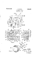
Fig. 1 is an elevation of a conventional reel embodying the improved anti-backlash device.
Fig. 2 is an enlarged fragmentary sectional view on line 2-2 of Fig. 1.
2,986,355 Patented May 30, 1961 Fig. 3 is a similar view showing the shoe in elevation.
Fig. 4 is an exploded perspective view of the shoe and the adjusting nut therefor.
The conventional reel shown in Fig. 1 has a spool shaf 10 journaled in the front and back plates 11 and 12, and the hub 13 of the spool is secured on the shaft 10 with the outer edges of the end plates 14 slidably engaging said front and back plates 11 and 12.
The crank handle 15 is mounted on a drive shaft 16 laterally offset from the spool shaft 10, and is operatively connected to said spool shaft in a usual manner by gearing within the gear case 17 on the front plate 11 of the reel. The plates 11 and 12 are'connected by posts 18 and 19, the larger post 19 preferably enclosing a level wind mechanism of well-known construction.
Between the hub 13 of the spool shaft. and the back plate 12, a 'click wheel 20 may be secured on the spool shaft, and a button 21 slidably mounted on the back plate is adapted to engage a click pawl (not shown) with the click wheel when desired.
The rear end portion 10' of the shaft is preferably reduced in diameter, and journaled in a bushing 22 in the back plate 12 and extending rearwardly of said plate. The projecting portion of the bushing 22 is exteriorly threaded and secures the end wall 23 of a cup-shaped housing 24 surrounding the bushing against the back plate 12. A cap nut 25 has an annular neck 26 extending into the housing 24 and screwed onto the bushing 22.
The end portion 10' of the shaft projects beyond the bushing 22 into a cylindrical chamber 27 in the cap nut 25, and the novel friction brake shoe 28 fits over the projecting end of shaft portion 10' and is housed in said chamber. The cap nut 25 may be used as an oil cup for supplying lubricant to the end portion 10' of the shaft where it is journaled in bushing 22, in which case an oil hole would be provided in the outer wall of the cap.
The shoe 28 is made of a substantially rigid material having some resiliency and high wear resistance. A preferred material is nylon, although other plastic materials having similar characteristics may be used. As shown, the shoe is tapered to be generally frusto-conical in shape with a socket 29 in its smaller end fitting loosely over and around the end of shaft portion 10'. Diametrically opposite notches 30 extending longitudinally of the shaft are provided through the socket wall forming opposed segmental portions 31, for a purpose to be described.
The larger end of the shoe is dished or recessed on its outer surface. Preferably, the recess 32 is arcuate and is curved in a direction substantially at right angles to a plane defined by the axes or longitudinal median lines of the notches 30, and the recess forms two end abutment projections 33 on the larger end of the shoe at and in alignment with the bases of segments 31 for abutting the outer wall 34 of the nut 25. It will be seen that when the cap nut 25 is screwed inwardly on bushing 22, the abutment of the outer wall 34 with projections 33 will flex the inner segmental portions 31 of the shoe formed by the notches 30, causing them to move radially inward and frictionally grip the shaft around diametrically opposite peripheral surfaces.
'Within the cup-shaped housing 24 is a tension spring 35 to hold the cap 25 in adjusted position. The spring 35 may be a curved or coil spring, one end of which frictionally engages the neck 26 of the cap and the other end frictionally engages the side wall of the housing.
Due to the fact that the shoe grips peripheral surfaces of substantial extent rather than merely abutting the end of the shaft, and to the character of the nylon material of the shoe, effective braking of the shaft is obtained with a minimum of pressure exerted by the cap nut. Moreover, a sensitive and accurate adjustment of the amount of friction applied is easily obtainable in order to con- 3 H01 backlash under varying conditions. is durable and easily replaceable.
What is claimed is:
1, In a fishing reel having an end plate and a spool shaft jom'naled at one end in said end plate, friction brake means to overcome backlash of the spool during casting, said means comprising a tapered nylon shoe having a socket at its smaller end fitting loosely around and abutting the end portion of said shaft and having diametrically opposite longitudinal notches passing through the wall of said socket forming opposed segments, the larger end of said shoe being recessed crosswise of a plane defined by the median lines of said notches and forming opposed end abutment portions at the bases of and in alignment with said segments, and a cap adjustably secured on said. end plate engaging said end abutment portions to flex said segments into frictional contact with peripheral surfaces of said shaft.
2. In a fishing reel having an end plate and a spool shaft journaled at one end in said end plate, a bushing The nylon shoe secured in said end plate journaling said shaft, friction brake means to overcome the backlash of the spool during casting, said means comprising a nylon shoe having opposed arcuate segments at one end fitting loosely around the end portion of the shaft, the other end of said shoe being recessed to form opposed end abutments at the bases of said segments, and a cap adjustably secured on said bushing engaging said end abutments to flex said segments radially inward into frictional contact with peripheral surfaces of said shaft.
References Cited in the file of this patent UNITED STATES PATENTS 1,450,738 Case Apr. 3, 1923 2,347,173 Coxe et a1 Apr. 25, 1944 2,518,482 Mandolf et a1 Aug. 15, 1950 2,705,113 Bonahno Mar. 29, 1955 FOREIGN PATENTS 731,588 Germany Feb. 11, 1943
Priority Applications (1)
| Application Number | Priority Date | Filing Date | Title |
|---|---|---|---|
| US851337A US2986355A (en) | 1959-11-06 | 1959-11-06 | Anti-backlash device |
Applications Claiming Priority (1)
| Application Number | Priority Date | Filing Date | Title |
|---|---|---|---|
| US851337A US2986355A (en) | 1959-11-06 | 1959-11-06 | Anti-backlash device |
Publications (1)
| Publication Number | Publication Date |
|---|---|
| US2986355A true US2986355A (en) | 1961-05-30 |
Family
ID=25310543
Family Applications (1)
| Application Number | Title | Priority Date | Filing Date |
|---|---|---|---|
| US851337A Expired - Lifetime US2986355A (en) | 1959-11-06 | 1959-11-06 | Anti-backlash device |
Country Status (1)
| Country | Link |
|---|---|
| US (1) | US2986355A (en) |
Cited By (2)
| Publication number | Priority date | Publication date | Assignee | Title |
|---|---|---|---|---|
| US4157795A (en) * | 1977-11-25 | 1979-06-12 | Turner Lenord H | Fishing reel |
| US4515325A (en) * | 1982-10-25 | 1985-05-07 | Coret & Co. Ltd. | Fly reel |
Citations (5)
| Publication number | Priority date | Publication date | Assignee | Title |
|---|---|---|---|---|
| US1450738A (en) * | 1921-11-19 | 1923-04-03 | Enterprise Mfg Co | Tension oil cap for fishing reels |
| DE731588C (en) * | 1940-09-10 | 1943-02-11 | Waggon Fabrik Uerdingen A G | Shaft friction clutch |
| US2347173A (en) * | 1939-10-09 | 1944-04-25 | Bronson Reel Company | Fishing reel |
| US2518482A (en) * | 1947-08-20 | 1950-08-15 | Langley Corp | Fishing reel |
| US2705113A (en) * | 1949-07-06 | 1955-03-29 | Airex Mfg Co Inc | Fishing reel |
-
1959
- 1959-11-06 US US851337A patent/US2986355A/en not_active Expired - Lifetime
Patent Citations (5)
| Publication number | Priority date | Publication date | Assignee | Title |
|---|---|---|---|---|
| US1450738A (en) * | 1921-11-19 | 1923-04-03 | Enterprise Mfg Co | Tension oil cap for fishing reels |
| US2347173A (en) * | 1939-10-09 | 1944-04-25 | Bronson Reel Company | Fishing reel |
| DE731588C (en) * | 1940-09-10 | 1943-02-11 | Waggon Fabrik Uerdingen A G | Shaft friction clutch |
| US2518482A (en) * | 1947-08-20 | 1950-08-15 | Langley Corp | Fishing reel |
| US2705113A (en) * | 1949-07-06 | 1955-03-29 | Airex Mfg Co Inc | Fishing reel |
Cited By (2)
| Publication number | Priority date | Publication date | Assignee | Title |
|---|---|---|---|---|
| US4157795A (en) * | 1977-11-25 | 1979-06-12 | Turner Lenord H | Fishing reel |
| US4515325A (en) * | 1982-10-25 | 1985-05-07 | Coret & Co. Ltd. | Fly reel |
Similar Documents
| Publication | Publication Date | Title |
|---|---|---|
| US3946963A (en) | Drag assembly for spinning reels with fixed indicator bezel | |
| US2760736A (en) | Electric power driven fishing reel | |
| US2648506A (en) | Fishing reel | |
| US2686016A (en) | Fishing reel | |
| US4634073A (en) | Brake for fish casting reel | |
| US9210920B1 (en) | Fishing reel with improved line management and control system and clicker mechanism | |
| US2986355A (en) | Anti-backlash device | |
| US4466580A (en) | Fishing reel | |
| US3967791A (en) | Spinning reel for fishing | |
| US2083927A (en) | Fishing reel | |
| US4408729A (en) | Star drag system for spin cast reels | |
| US3152771A (en) | Fishing reel | |
| US6513743B1 (en) | Anti-reverse large arbor fly reel | |
| US2384561A (en) | Nonbacklash device for fishing reels | |
| US3184179A (en) | Fishing reel with friction drive | |
| US2766956A (en) | Salt water spinning reel | |
| US3072356A (en) | Fishing line reel | |
| US3958771A (en) | Fishing reel | |
| US2205641A (en) | Fishing-reel brake | |
| US3000586A (en) | Fishing reel | |
| US3556428A (en) | Articles for inhibiting entangling of a fishing line on a fishing line reel | |
| US3223348A (en) | Spin-cast fishing reel with level winding means | |
| US10939674B1 (en) | Bearing supported pick-up pin for spincast reel | |
| US2551567A (en) | Fishing reel | |
| US4756487A (en) | Spin cast reel with rear drag adjustment |