US29809A - Alexander morton - Google Patents
Alexander morton Download PDFInfo
- Publication number
- US29809A US29809A US29809DA US29809A US 29809 A US29809 A US 29809A US 29809D A US29809D A US 29809DA US 29809 A US29809 A US 29809A
- Authority
- US
- United States
- Prior art keywords
- rolls
- blanks
- pair
- axes
- morton
- Prior art date
- Legal status (The legal status is an assumption and is not a legal conclusion. Google has not performed a legal analysis and makes no representation as to the accuracy of the status listed.)
- Expired - Lifetime
Links
- 238000005096 rolling process Methods 0.000 description 7
- 230000008878 coupling Effects 0.000 description 6
- 238000010168 coupling process Methods 0.000 description 6
- 238000005859 coupling reaction Methods 0.000 description 6
- 238000004519 manufacturing process Methods 0.000 description 4
- 230000005540 biological transmission Effects 0.000 description 2
- 238000000034 method Methods 0.000 description 2
- 240000001973 Ficus microcarpa Species 0.000 description 1
- 206010052849 Oblique presentation Diseases 0.000 description 1
- 230000015572 biosynthetic process Effects 0.000 description 1
- 229910003460 diamond Inorganic materials 0.000 description 1
- 239000010432 diamond Substances 0.000 description 1
- PCHJSUWPFVWCPO-UHFFFAOYSA-N gold Chemical compound [Au] PCHJSUWPFVWCPO-UHFFFAOYSA-N 0.000 description 1
- 239000010931 gold Substances 0.000 description 1
- 229910052737 gold Inorganic materials 0.000 description 1
- 230000001788 irregular Effects 0.000 description 1
- 239000002184 metal Substances 0.000 description 1
- 229910052751 metal Inorganic materials 0.000 description 1
- 230000001105 regulatory effect Effects 0.000 description 1
- 230000000284 resting effect Effects 0.000 description 1
Images
Classifications
-
- B—PERFORMING OPERATIONS; TRANSPORTING
- B21—MECHANICAL METAL-WORKING WITHOUT ESSENTIALLY REMOVING MATERIAL; PUNCHING METAL
- B21H—MAKING PARTICULAR METAL OBJECTS BY ROLLING, e.g. SCREWS, WHEELS, RINGS, BARRELS, BALLS
- B21H1/00—Making articles shaped as bodies of revolution
- B21H1/22—Making articles shaped as bodies of revolution characterised by use of rolls having circumferentially varying profile ; Die-rolling
Definitions
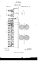
- FIG. 2 is a front elevation of my invention.
- Fig. 2 a transverse vertical section of the same taken in the line zr, x, Fig. l.
- Fig. 3 a transverse vertical section of the same, taken in the line 1, g/Fig 1.
- Figs. t and 5 enlarged transverse vertical sections of two pairs of rollers of the same.
- Fig. 6, a face view of a blank previous to being rolled.
- the object of the within described invention is to obviate these difficulties, expedite the rolling process, produce perfect work with unskilled labor, and at the saine time economize in stock.
- the invention consists in the employment or use of a train of rolls so arranged as to be capable of rolling out or attenuating the blanks by a series of consecutive operations without changing the set of the rolls.
- the invention also consists in a novel way of connecting the axes of said rolls to compensate for any imperfectness in the driving gear, and also in a peculiar relative formation of the eccentric rolls one with another to obtain a differential pressure.
- rlhe invention also further consists in the employment or use of guide rests for the purpose of insuring the proper presentation of the blanks to the bite of the rolls, and keeping them at right angles to the rolls while passing through or between them.
- A represents a base of any suitable length to which a series of heads B, are secured. These heads B, are slotted vertically to receive the journals o, of rolls C, D.
- the upper rolls C are cylindrical lout the lower ones D, are eccentric, each lower roll having an eccentric portion b, in its periphery see Figs. 3, l and 5.
- the journals of the upper rolls C have bearings c, resting on them, and on each bearing c, a set screw d, bears, said screws passing through the upper parts of the heads B, as shown clearly in Figs. l, 2, and 3.
- the journals a, of the upper rolls C rest on bars ctx, which bear on the upper ends of springs bx.
- the eccentric portions I), of the lower rolls D are not similar, there being a gradual variation from the first pair of rolls, designated by N o. l, to the last pair designated by No. 7.
- These eccentric portions Z) are so formed as to give a differential pressure to the blanks, causing the bite of the rolls, and the pressure to vary consecutively at dierent points as may be required to insure proper elasticity and produce a perfect pen.
- the pressure or set of each pair of rolls is lirst regulated by the set screws (Z, but when said rollers are once set for the rolling out of blanks of a certain style or class, their position is not changed or varied at any time during the process of the work, the bearings of each pair of rolls, so far as their set is concerned, when once given, being fixtures.
- rIhe couplings f are not fitted tightly on the parts e, of the aXes of the rollers, a certain degree of play is allowed so as to form a brake between the aXes of each pair of rolls; and serve to prevent the perfect trans mission of any inaccuracy in the movement of one pair of rollers to the others, for instance, gears cannot as is well known, be so accurately constructed but what somedegree of an irregular movement will be communi cated to the parts which they drive, and therefore the gears g, g, will, if a rigid connection be used between the several pairs of rolls C, D, be the cause of the rolls giving a wavy surface to the blanks upon which they operate.
- the blanks may be very expeditiously rolled as no adjustment of the rolls is required during the process, the mere manipulation of passing the blanks successively between the rolls being all that is necessary, hence any one of ordinary ability may perform the work. It will also be seen that the rolling of the blanks will be done uniformly, all being alike, and the work also performed expeditiously, and there will be no unnecessary working up of the stock, as no after work or stoning away of the blanks is required in order to produce uniformity and a necessary degree of elasticity as is the case by the ordinary mode of manufacture.
Landscapes
- Engineering & Computer Science (AREA)
- Mechanical Engineering (AREA)
- Bending Of Plates, Rods, And Pipes (AREA)
Description
orrrcn.
ALEXANDER MOR-TON, OF NEV YORK, N. Y.
MACHINE FOR ROLLING GOLD PENS.
Specification of-Letters Patent No. 29,809, dated August 28, 1860.
To all whom fit may concern:
Be it known that I, ALEXANDER MoRToN, of the city, county, and State of New York, have invented a new and Improved Machine for Rolling Blanks in the Manufacture of Gold Pens; and I do hereby declare that the following is a full, clear, and exact description of the same, reference being had to the annexed drawings, making a part of this specication, in which- Figure l, is a front elevation of my invention. Fig. 2, a transverse vertical section of the same taken in the line zr, x, Fig. l. Fig. 3, a transverse vertical section of the same, taken in the line 1, g/Fig 1. Figs. t and 5, enlarged transverse vertical sections of two pairs of rollers of the same. Fig. 6, a face view of a blank previous to being rolled.
Similar letters of reference indicate corresponding parts in the several figures.
In rolling blanks for the manufacture of gold pens one pair of rolls only have heretofore been employed, and the blanks have necessarily been subjected to successive pressures by adjusting one pair of rollers. In the rolling out and attenuating o-f the blanks great precision and exactness are required in order to produce perfect work, and the employment or use of one pair of rolls only, involves the necessity of various adjustments which lead to inaccuracies of workmanship and a general lack of uniformity in the production of the work. In addition to this the employment only of one set of rolls precludes the obtaining of a differential pressure, that is to say, the gradual and successive varying of the bite of the rolls from the diamond or point of the blank, in order to obtain a gradual taper or attenuation from point to back as may be required.
The object of the within described invention is to obviate these difficulties, expedite the rolling process, produce perfect work with unskilled labor, and at the saine time economize in stock. The invention consists in the employment or use of a train of rolls so arranged as to be capable of rolling out or attenuating the blanks by a series of consecutive operations without changing the set of the rolls. The invention also consists in a novel way of connecting the axes of said rolls to compensate for any imperfectness in the driving gear, and also in a peculiar relative formation of the eccentric rolls one with another to obtain a differential pressure.
rlhe invention also further consists in the employment or use of guide rests for the purpose of insuring the proper presentation of the blanks to the bite of the rolls, and keeping them at right angles to the rolls while passing through or between them.
To enable those skilled in the art to fully understand and construct my invention I will proceed to describe it.
A, represents a base of any suitable length to which a series of heads B, are secured. These heads B, are slotted vertically to receve the journals o, of rolls C, D. The upper rolls C, are cylindrical lout the lower ones D, are eccentric, each lower roll having an eccentric portion b, in its periphery see Figs. 3, l and 5. The journals of the upper rolls C, have bearings c, resting on them, and on each bearing c, a set screw d, bears, said screws passing through the upper parts of the heads B, as shown clearly in Figs. l, 2, and 3. The journals a, of the upper rolls C, rest on bars ctx, which bear on the upper ends of springs bx. These springs bx, have a tendency to keep the upper rolls C, elevated. The axes of the rolls C, D, beyond the journals a, are of quadrilateral form as shown at c, and the several axes are connected by square or quadrilateral couplings f, which are fitted on the parts e, as shown clearly in Fig. l, in which two of the heads B, are bisected vertically. All the rolls being thus connectedthe upper and lower rolls are turned simultaneously by means of gears g, g, which mesh into each other and have their axes connected by couplings f, to the axes of the rolls at one end of the machine, see Fig. l. Power is transmitted to the axis of the lower gear g, by any suitable gearing la. The eccentric portions I), of the lower rolls D, are not similar, there being a gradual variation from the first pair of rolls, designated by N o. l, to the last pair designated by No. 7. These eccentric portions Z), are so formed as to give a differential pressure to the blanks, causing the bite of the rolls, and the pressure to vary consecutively at dierent points as may be required to insure proper elasticity and produce a perfect pen. The pressure or set of each pair of rolls is lirst regulated by the set screws (Z, but when said rollers are once set for the rolling out of blanks of a certain style or class, their position is not changed or varied at any time during the process of the work, the bearings of each pair of rolls, so far as their set is concerned, when once given, being fixtures.
rIhe couplings f, are not fitted tightly on the parts e, of the aXes of the rollers, a certain degree of play is allowed so as to form a brake between the aXes of each pair of rolls; and serve to prevent the perfect trans mission of any inaccuracy in the movement of one pair of rollers to the others, for instance, gears cannot as is well known, be so accurately constructed but what somedegree of an irregular movement will be communi cated to the parts which they drive, and therefore the gears g, g, will, if a rigid connection be used between the several pairs of rolls C, D, be the cause of the rolls giving a wavy surface to the blanks upon which they operate. This difficulty is avoided by the use of the couplings f, which divide the imperfection of the movement between each pair of rolls so that the irregularity of the movement of the gears g, will be lost in its transmission through the coupling f, of the train of rolls, the few last pair of rolls of the series working in a perfect manner or giving a smooth exterior to the blanks. Between the heads B, and opposite each pair of rolls C, D, a guide or rest E, is placed. These guides or -rests are simply metal plates recessed in their upper ends as shown at L', to receive the blanks, the recesses corresponding in width to the blanks. The bottoms of the recesses h, are on a level with the bite of the rolls, as shown clearly in Fig. 3, and insure the blanks being fed horizontally between the rolls, and at right angles to their aXes. These guides are important as an improper or oblique presentation of the blank to the rolls is attended with a corresponding elongation of one side of the blank. The blanks, the form of which is shown in Fig. 6, are passed successively between the rolls C, D, from No. 1 to 7, each pair of rolls performing their proper work in accordance with their adjustment at the commencement of the work and the form and position of the eccentric portion Z), of the lower rolls.
It will be seen from the above description that the blanks may be very expeditiously rolled as no adjustment of the rolls is required during the process, the mere manipulation of passing the blanks successively between the rolls being all that is necessary, hence any one of ordinary ability may perform the work. It will also be seen that the rolling of the blanks will be done uniformly, all being alike, and the work also performed expeditiously, and there will be no unnecessary working up of the stock, as no after work or stoning away of the blanks is required in order to produce uniformity and a necessary degree of elasticity as is the case by the ordinary mode of manufacture.
I do not confine myself to any particular number of pairs of rolls for a greater or less number may be used as circumstances may require, but
I do claim as new, and desire to secure by Letters Patent- 1. The connecting of the axes of the rolls C, D, by means of the couplings f, when said rolls are arranged substantially as and for the purpose specified.
2. The forming of the eccentric portions Z, on the lower rolls D, in such a way or in such positions relatively with each other, that the bite of the rolls may act consecu tively at different points on the blanks and produce the differential pressure as set forth.
3. In connection with the train of rolls C, D, the guides or rests E, placed relatively witlh the rolls as and for the Apurpose specifier.
A. MORTON.
Vitnesses:
WM. THOMPSON, M. M. LIVINGSTON.
Publications (1)
| Publication Number | Publication Date |
|---|---|
| US29809A true US29809A (en) | 1860-08-28 |
Family
ID=2099459
Family Applications (1)
| Application Number | Title | Priority Date | Filing Date |
|---|---|---|---|
| US29809D Expired - Lifetime US29809A (en) | Alexander morton |
Country Status (1)
| Country | Link |
|---|---|
| US (1) | US29809A (en) |
-
0
- US US29809D patent/US29809A/en not_active Expired - Lifetime
Similar Documents
| Publication | Publication Date | Title |
|---|---|---|
| US29809A (en) | Alexander morton | |
| US18058A (en) | Improved bending-machine | |
| US113708A (en) | Improvement in rolls for rolling hoop, bar, and rod-iron | |
| US318889A (en) | Flanging machine | |
| US16793A (en) | Steel springs | |
| US16215A (en) | James reynolds | |
| USRE644E (en) | Improved machine for making hames | |
| US24557A (en) | Improvement in machines for making upholstery-springs | |
| US29773A (en) | Improvement in sugar-cane mills | |
| US1184893A (en) | Machine for forming calks. | |
| US1965A (en) | Lewis grandy and thomas osgood | |
| US37274A (en) | Improvement in rolling-mill stands | |
| US396361A (en) | Rolling-die machine | |
| US3690A (en) | Machinery foe | |
| US46967A (en) | Assigrnob to benedict | |
| US20737A (en) | Stave-machine | |
| US435481A (en) | Heel stiffener machine | |
| US103397A (en) | Improved machine for rolling metals | |
| US26792A (en) | Machine for finishing leather | |
| US29500A (en) | Machine foe | |
| US53025A (en) | Improved machine for rolling file-blanks | |
| US119716A (en) | Improvement in machines for bending tires | |
| US87512A (en) | George reynolds | |
| US18991A (en) | Volute springs | |
| US361188A (en) | Machinery for the manufacture of eye-bars |